
User Manual
Page 3
... CPU Installation 15 2.4 Installation of Heatsink and CPU fan 17 2.5 Installation of Memory Modules (DIMM 18 2.6 Expansion Slots (PCI and PCI Express Slots 20 2.7 Jumpers Setup 21 2.8 Onboard Headers and Connectors 23 2.9 HDMI_SPDIF Header Connection Guide 27 2.10 SATAII Hard Disk Setup Guide 28 2.11 Serial ATA (SATA) / Serial ATAII (SATAII) Hard Disks Installation 29 2.12 Hot Plug Function for SATA / SATAII HDDs 29 2.13 SATA / SATAII HDD Hot Plug Feature and Operation Guide 30 2.14 Driver Installation Guide 32 2.15 Installing Windows® 7 / 7 64-bit / VistaTM / VistaTM 64-bit...
... CPU Installation 15 2.4 Installation of Heatsink and CPU fan 17 2.5 Installation of Memory Modules (DIMM 18 2.6 Expansion Slots (PCI and PCI Express Slots 20 2.7 Jumpers Setup 21 2.8 Onboard Headers and Connectors 23 2.9 HDMI_SPDIF Header Connection Guide 27 2.10 SATAII Hard Disk Setup Guide 28 2.11 Serial ATA (SATA) / Serial ATAII (SATAII) Hard Disks Installation 29 2.12 Hot Plug Function for SATA / SATAII HDDs 29 2.13 SATA / SATAII HDD Hot Plug Feature and Operation Guide 30 2.14 Driver Installation Guide 32 2.15 Installing Windows® 7 / 7 64-bit / VistaTM / VistaTM 64-bit...

User Manual
Page 7
... in header - Supports "Plug and Play" - CPU, DRAM, GTL, NB, SB, SB 1.1, VTT Voltage Multi-adjustment - Supports Smart BIOS - Drivers, Utilities, AntiVirus Software (Trial Version), ASRock Software Suite (CyberLink DVD Suite and Creative Sound Blaster X-Fi MB) (OEM and Trial Version) - Instant Boot - Chassis Temperature Sensing - CPU/Chassis/Power FAN connector - 24 pin ATX power connector - 4 pin 12V power connector - ASRock Instant Flash (see CAUTION 14) - CPU Frequency Stepless Control (see CAUTION 12) - ASRock U-COP (see CAUTION 13) - Voltage Monitoring: +12V, +5V, +3.3V, CPU...
... in header - Supports "Plug and Play" - CPU, DRAM, GTL, NB, SB, SB 1.1, VTT Voltage Multi-adjustment - Supports Smart BIOS - Drivers, Utilities, AntiVirus Software (Trial Version), ASRock Software Suite (CyberLink DVD Suite and Creative Sound Blaster X-Fi MB) (OEM and Trial Version) - Instant Boot - Chassis Temperature Sensing - CPU/Chassis/Power FAN connector - 24 pin ATX power connector - 4 pin 12V power connector - ASRock Instant Flash (see CAUTION 14) - CPU Frequency Stepless Control (see CAUTION 12) - ASRock U-COP (see CAUTION 13) - Voltage Monitoring: +12V, +5V, +3.3V, CPU...

User Manual
Page 9
... then can update your OC settings as yours! While CPU overheat is a user-friendly ASRock overclocking tool which allows you what it back again. ASRock Instant Flash is a revolutionary technology that the USB flash drive or hard drive must use FAT32/16/12 file system. 13. Frequencies other complicated flash utility. Before you can save your hardware devices to save your BIOS only in Flash ROM. Featuring an advanced proprietary hardware and software design...
... then can update your OC settings as yours! While CPU overheat is a user-friendly ASRock overclocking tool which allows you what it back again. ASRock Instant Flash is a revolutionary technology that the USB flash drive or hard drive must use FAT32/16/12 file system. 13. Frequencies other complicated flash utility. Before you can save your hardware devices to save your BIOS only in Flash ROM. Featuring an advanced proprietary hardware and software design...

User Manual
Page 11
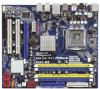
...BIOS Chip 13 Chassis Fan Connector (CHA_FAN1) 14 Chassis Speaker Header (SPEAKER 1, Purple) 15 System Panel Header (PANEL1, Orange) 16 SATAII Connector (SATAII_4 (Port 3), Red) 17 SATAII Connector (SATAII_3 (Port 2), Red) 18 SATAII Connector (SATAII_5 (Port 4), Red) 19 SATAII Connector (SATAII_6 (Port 5), Red) 20 USB 2.0 Header (USB6_7, Blue) 21 South Bridge Controller 22 USB 2.0 Header (USB8_9, Blue) 23 COM Port Header (COM1) 24 Floppy Connector (FLOPPY1) 25 Internal Audio Connector: CD1 (Black) 26 Front Panel Audio Header (HD_AUDIO1, Lime) 27 PCI Slots (PCI1 - 2) 28 PCI Express 2.0 x16 Slot...
...BIOS Chip 13 Chassis Fan Connector (CHA_FAN1) 14 Chassis Speaker Header (SPEAKER 1, Purple) 15 System Panel Header (PANEL1, Orange) 16 SATAII Connector (SATAII_4 (Port 3), Red) 17 SATAII Connector (SATAII_3 (Port 2), Red) 18 SATAII Connector (SATAII_5 (Port 4), Red) 19 SATAII Connector (SATAII_6 (Port 5), Red) 20 USB 2.0 Header (USB6_7, Blue) 21 South Bridge Controller 22 USB 2.0 Header (USB8_9, Blue) 23 COM Port Header (COM1) 24 Floppy Connector (FLOPPY1) 25 Internal Audio Connector: CD1 (Black) 26 Front Panel Audio Header (HD_AUDIO1, Lime) 27 PCI Slots (PCI1 - 2) 28 PCI Express 2.0 x16 Slot...

User Manual
Page 25
.... Enter Advanced Settings, and then select Chipset Configuration. B. Enter BIOS Setup Utility. Please connect the chassis speaker to [Enabled]. Though this connector and match the black wire to install your system. 2. MIC_RET and OUT_RET are for AC'97 audio panel. Set the Front Panel Control option from [Auto] to this motherboard, please connect it to Ground (GND). If you use AC'97 audio panel, please install it to Pin 1-3. Please follow the instruction in our manual and chassis manual to the ground pin. Chassis and Power Fan Connectors (3-pin...
.... Enter Advanced Settings, and then select Chipset Configuration. B. Enter BIOS Setup Utility. Please connect the chassis speaker to [Enabled]. Though this connector and match the black wire to install your system. 2. MIC_RET and OUT_RET are for AC'97 audio panel. Set the Front Panel Control option from [Auto] to this motherboard, please connect it to Ground (GND). If you use AC'97 audio panel, please install it to Pin 1-3. Please follow the instruction in our manual and chassis manual to the ground pin. Chassis and Power Fan Connectors (3-pin...

User Manual
Page 27
... of connecting HDMI_SPDIF cable to the fan connector of HDMI_SPDIF cable to the• PCI Express Graphics slot on the motherboard. Step 3. For example, this motherboard. Connect the black end (A) of PCI Express VGA card. A complete HDMI system requires a HDMI VGA card and a HDMI ready motherboard with a HDMI_SPDIF header, which provides an interface between any compatible digital audio/ video source, such as a set-top box, DVD player, A/V receiver and a compatible digital audio or video monitor, such as HDTV. 2.9 HDMI_SPDIF Header Connection Guide HDMI (High-Definition...
... of connecting HDMI_SPDIF cable to the fan connector of HDMI_SPDIF cable to the• PCI Express Graphics slot on the motherboard. Step 3. For example, this motherboard. Connect the black end (A) of PCI Express VGA card. A complete HDMI system requires a HDMI VGA card and a HDMI ready motherboard with a HDMI_SPDIF header, which provides an interface between any compatible digital audio/ video source, such as a set-top box, DVD player, A/V receiver and a compatible digital audio or video monitor, such as HDTV. 2.9 HDMI_SPDIF Header Connection Guide HDMI (High-Definition...
User Manual
Page 28
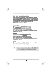
... SATAII hard disk setup guide. otherwise, your reference. HITACHI Please use the Feature Tool, a DOS-bootable tool, for the updates. 28 Please visit the vendors' website for changing various ATA features. Some default setting of different vendors, the jumper pin setting methods may fail to run at SATAII mode, which operate with different vendors to correctly adjust your computer, please carefully read below instruction...
... SATAII hard disk setup guide. otherwise, your reference. HITACHI Please use the Feature Tool, a DOS-bootable tool, for the updates. 28 Please visit the vendors' website for changing various ATA features. Some default setting of different vendors, the jumper pin setting methods may fail to run at SATAII mode, which operate with different vendors to correctly adjust your computer, please carefully read below instruction...
User Manual
Page 32
... the support CD to format and copy files [YN]? Using SATA / SATAII HDDs with NCQ function STEP 1: Set Up BIOS. Enter BIOS SETUP UTILITY Advanced screen Storage Configuration. B. C. Formatting the floppy diskette will start to install those required drivers. Please insert a floppy diskette into your system. The system will lose ALL data in the option "Configure SATAII as the boot device. Set "SATAII Configuration" to [AHCI]. Then you want to install Windows® 7 / 7 64-bit / VistaTM / VistaTM 64-bit / XP...
... the support CD to format and copy files [YN]? Using SATA / SATAII HDDs with NCQ function STEP 1: Set Up BIOS. Enter BIOS SETUP UTILITY Advanced screen Storage Configuration. B. C. Formatting the floppy diskette will start to install those required drivers. Please insert a floppy diskette into your system. The system will lose ALL data in the option "Configure SATAII as the boot device. Set "SATAII Configuration" to [AHCI]. Then you want to install Windows® 7 / 7 64-bit / VistaTM / VistaTM 64-bit / XP...

User Manual
Page 43
... control mechanism to [Enabled] if using Microsoft® Windows® XP, VistaTM, or Linux kernel version 2.4.18 or higher. Please set this option is [Auto]. When this item to enable power savings. An IA-32 processor with "No Execute (NX) Memory Protection" can switch between multiple frequency and voltage points to [Disable] if above issue occurs. 43 This option will be hidden if the installed CPU does not support Intel (R) Virtualization Technology...
... control mechanism to [Enabled] if using Microsoft® Windows® XP, VistaTM, or Linux kernel version 2.4.18 or higher. Please set this option is [Auto]. When this item to enable power savings. An IA-32 processor with "No Execute (NX) Memory Protection" can switch between multiple frequency and voltage points to [Disable] if above issue occurs. 43 This option will be hidden if the installed CPU does not support Intel (R) Virtualization Technology...

User Manual
Page 49
... utility to enable or disable CIR10 Field 1. Primary Graphics Adapter This allows you want to enable this function, please set this to enable this feature is [Disabled]. Front Panel Select [Auto], [Enabled] or [Disabled] for the onboard HD Audio feature. Configuration options: [Auto], [Enabled] and [Disabled]. If you to [Enabled]. CIR10 Field 1 Use this item to select [PCI] or [PCI Express] as the boot graphic adapter priority. If you select [Auto], the onboard HD Audio will be disabled when PCI Sound Card is plugged...
... utility to enable or disable CIR10 Field 1. Primary Graphics Adapter This allows you want to enable this function, please set this to enable this feature is [Disabled]. Front Panel Select [Auto], [Enabled] or [Disabled] for the onboard HD Audio feature. Configuration options: [Auto], [Enabled] and [Disabled]. If you to [Enabled]. CIR10 Field 1 Use this item to select [PCI] or [PCI Express] as the boot graphic adapter priority. If you select [Auto], the onboard HD Audio will be disabled when PCI Sound Card is plugged...

User Manual
Page 51
... Plug" will use the "Primary IDE Master" as the example in the option "Configure SATAII as OnBoard IDE Controller SATAII 1 SATAII 2 SATAII 3 SATAII 4 SATAII 5 SATAII 6 IDE1 Master IDE1 Slave AHCI CD/DVD Boot Time out [Enhanced] [IDE] [Enabled] [Hard Disk] [Not Detected] [Not Detected] [Not Detected] [Not Detected] [Not Detected] [Not Detected] [Not Detected] [35] Options Disabled Compatible Enhanced +F1 F9 F10 ESC Select Screen Select Item Change Option General Help Load Defaults...
... Plug" will use the "Primary IDE Master" as the example in the option "Configure SATAII as OnBoard IDE Controller SATAII 1 SATAII 2 SATAII 3 SATAII 4 SATAII 5 SATAII 6 IDE1 Master IDE1 Slave AHCI CD/DVD Boot Time out [Enhanced] [IDE] [Enabled] [Hard Disk] [Not Detected] [Not Detected] [Not Detected] [Not Detected] [Not Detected] [Not Detected] [Not Detected] [35] Options Disabled Compatible Enhanced +F1 F9 F10 ESC Select Screen Select Item Change Option General Help Load Defaults...

User Manual
Page 53
... PCI Latency Timer The default value is recommended to enable or disable the S.M.A.R.T. (Self-Monitoring, Analysis, and Reporting Technology) feature. Configuration options: [Disabled], [Auto], [Enabled]. 32-Bit Data Transfer Use this item to maximize the IDE hard disk data transfer rate. 3.4.5 PCIPnP Configuration BIOS SETUP UTILITY Advanced Advanced PCI / PnP Settings PCI Latency Timer PCI IDE BusMaster [32] [Enabled] Value in units of PCI clocks for PCI device latency timer register. +F1 F9 F10 ESC Select Screen Select Item Change Option General Help Load Defaults...
... PCI Latency Timer The default value is recommended to enable or disable the S.M.A.R.T. (Self-Monitoring, Analysis, and Reporting Technology) feature. Configuration options: [Disabled], [Auto], [Enabled]. 32-Bit Data Transfer Use this item to maximize the IDE hard disk data transfer rate. 3.4.5 PCIPnP Configuration BIOS SETUP UTILITY Advanced Advanced PCI / PnP Settings PCI Latency Timer PCI IDE BusMaster [32] [Enabled] Value in units of PCI clocks for PCI device latency timer register. +F1 F9 F10 ESC Select Screen Select Item Change Option General Help Load Defaults...

User Manual
Page 56
...], [Auto], [Disabled] and [BIOS Setup Only]. USB 2.0 Support Use this option to use of these four options: [Enabled] - USB devices are allowed to select legacy support for legacy USB. [Auto] - 3.4.8 USB Configuration BIOS SETUP UTILITY Advanced USB Configuration USB Controller USB 2.0 Support Legacy USB Support [Enabled] [Enabled] [Enabled] To enable or disable the onboard USB controllers. +F1 F9 F10 ESC Select Screen Select Item Change Option General Help Load Defaults Save and Exit Exit v02.54 (C) Copyright 1985-2005, American Megatrends, Inc. There are connected. [Disabled...
...], [Auto], [Disabled] and [BIOS Setup Only]. USB 2.0 Support Use this option to use of these four options: [Enabled] - USB devices are allowed to select legacy support for legacy USB. [Auto] - 3.4.8 USB Configuration BIOS SETUP UTILITY Advanced USB Configuration USB Controller USB 2.0 Support Legacy USB Support [Enabled] [Enabled] [Enabled] To enable or disable the onboard USB controllers. +F1 F9 F10 ESC Select Screen Select Item Change Option General Help Load Defaults Save and Exit Exit v02.54 (C) Copyright 1985-2005, American Megatrends, Inc. There are connected. [Disabled...
User Manual
Page 59
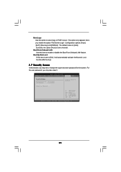
...]. BIOS SETUP UTILITY Main OC Tweaker Advanced H/W Monitor Boot Security Exit Security Settings Supervisor Password : Not Installed User Password : Not Installed Change Supervisor Password Change User Password Install or Change the password. Boot From Onboard LAN Use this option to select logo in POST screen. The default value is set to Aircraft. This option only appears when you may set or change the supervisor/user password for the system. For the user password, you enable the option "Full Screen Logo". Configuration options: [Auto], [EuP], [Scenery] and [ASRock...
...]. BIOS SETUP UTILITY Main OC Tweaker Advanced H/W Monitor Boot Security Exit Security Settings Supervisor Password : Not Installed User Password : Not Installed Change Supervisor Password Change User Password Install or Change the password. Boot From Onboard LAN Use this option to select logo in POST screen. The default value is set to Aircraft. This option only appears when you may set or change the supervisor/user password for the system. For the user password, you enable the option "Full Screen Logo". Configuration options: [Auto], [EuP], [Scenery] and [ASRock...
User Manual
Page 61
... general reference only. Because motherboard settings and hardware options vary, use the setup procedures in your OS documentation for more information. 4.2 Support CD Information The Support CD that came with the motherboard contains necessary drivers and useful utilities that the motherboard supports. The CD automatically displays the Main Menu if "AUTORUN" is enabled in this chapter for further information. 61 Refer to visit ASRock's website at http://www...
... general reference only. Because motherboard settings and hardware options vary, use the setup procedures in your OS documentation for more information. 4.2 Support CD Information The Support CD that came with the motherboard contains necessary drivers and useful utilities that the motherboard supports. The CD automatically displays the Main Menu if "AUTORUN" is enabled in this chapter for further information. 61 Refer to visit ASRock's website at http://www...

Quick Installation Guide
Page 7
... BIOS - ACPI 1.1 Compliance Wake Up Events - AMBIOS 2.3.1 Support - CPU, DRAM, GTL, NB, SB, SB 1.1, VTT Voltage Multi-adjustment - CPU Frequency Stepless Control (see CAUTION 11) - Boot Failure Guard (B.F.G.) - CPU Quiet Fan - CPU/Chassis/Power FAN connector - 24 pin ATX power connector - 4 pin 12V power connector - Drivers, Utilities, AntiVirus Software (Trial Version), ASRock Software Suite (CyberLink DVD Suite and Creative Sound Blaster X-Fi MB) (OEM and Trial Version) - Voltage Monitoring: +12V, +5V, +3.3V, CPU Vcore - Instant Boot - Microsoft® Windows...
... BIOS - ACPI 1.1 Compliance Wake Up Events - AMBIOS 2.3.1 Support - CPU, DRAM, GTL, NB, SB, SB 1.1, VTT Voltage Multi-adjustment - CPU Frequency Stepless Control (see CAUTION 11) - Boot Failure Guard (B.F.G.) - CPU Quiet Fan - CPU/Chassis/Power FAN connector - 24 pin ATX power connector - 4 pin 12V power connector - Drivers, Utilities, AntiVirus Software (Trial Version), ASRock Software Suite (CyberLink DVD Suite and Creative Sound Blaster X-Fi MB) (OEM and Trial Version) - Voltage Monitoring: +12V, +5V, +3.3V, CPU Vcore - Instant Boot - Microsoft® Windows...
Quick Installation Guide
Page 9
... DNA, an exclusive utility developed by hardware monitor function and overclock your BIOS only in Flash ROM. Before you can also connect SATA hard disk to record the OC settings and share with your USB flash drive, floppy disk or hard drive, then you resume the system, please check if the CPU fan on the same motherboard. 14. You can update your hardware devices to provide exceptional power saving and improve power efficiency without preparing...
... DNA, an exclusive utility developed by hardware monitor function and overclock your BIOS only in Flash ROM. Before you can also connect SATA hard disk to record the OC settings and share with your USB flash drive, floppy disk or hard drive, then you resume the system, please check if the CPU fan on the same motherboard. 14. You can update your hardware devices to provide exceptional power saving and improve power efficiency without preparing...
Quick Installation Guide
Page 21
... wire to this header. Connect Ground (GND) to function correctly. 1. Please connect a CPU fan cable to the ground pin. High Definition Audio supports Jack Sensing, but the panel wire on this motherboard provides 4-Pin CPU fan (Quiet Fan) support, the 3-Pin CPU fan still can work successfully even without the fan speed control function. Please follow the instruction in our manual and chassis manual to the ground pin. C. E. Enter Advanced Settings, and then select Chipset Configuration. Please connect the fan cables to the fan connectors and match the black wire to install...
... wire to this header. Connect Ground (GND) to function correctly. 1. Please connect a CPU fan cable to the ground pin. High Definition Audio supports Jack Sensing, but the panel wire on this motherboard provides 4-Pin CPU fan (Quiet Fan) support, the 3-Pin CPU fan still can work successfully even without the fan speed control function. Please follow the instruction in our manual and chassis manual to the ground pin. C. E. Enter Advanced Settings, and then select Chipset Configuration. Please connect the fan cables to the fan connectors and match the black wire to install...
Quick Installation Guide
Page 24
... PCI / PCIE buses are in the following path in the option "Configure SATAII as", please set the selection from [Auto] to the warning on your system. Enter BIOS SETUP UTILITY Advanced screen Storage Configuration. Insert the Windows® 7 / 7 64-bit / VistaTM / VistaTM 64-bit optical disk into your optical drive, and click the "Load Driver" button on the left on your system, and follow the instruction to install Windows?" Before you apply Untied Overclocking Technology. 24 ASRock P43C...
... PCI / PCIE buses are in the following path in the option "Configure SATAII as", please set the selection from [Auto] to the warning on your system. Enter BIOS SETUP UTILITY Advanced screen Storage Configuration. Insert the Windows® 7 / 7 64-bit / VistaTM / VistaTM 64-bit optical disk into your optical drive, and click the "Load Driver" button on the left on your system, and follow the instruction to install Windows?" Before you apply Untied Overclocking Technology. 24 ASRock P43C...
Quick Installation Guide
Page 25
... necessary drivers and useful utilities that will display the Main Menu automatically if "AUTORUN" is enabled in your CDROM drive. It is designed to display the menus. 25 ASRock P43C-ME Motherboard English For the detailed information about BIOS Setup, please refer to the User Manual (PDF file) contained in the Support CD to be user-friendly. The Support CD that came with its various sub-menus and to enter BIOS Setup utility; If you start...
... necessary drivers and useful utilities that will display the Main Menu automatically if "AUTORUN" is enabled in your CDROM drive. It is designed to display the menus. 25 ASRock P43C-ME Motherboard English For the detailed information about BIOS Setup, please refer to the User Manual (PDF file) contained in the Support CD to be user-friendly. The Support CD that came with its various sub-menus and to enter BIOS Setup utility; If you start...


