
User Manual
Page 4
3.4.5 PCIPnP Configuration 47 3.4.6 Super IO Configuration 47 3.4.7 USB Configuration 48 3.5 Hardware Health Event Monitoring Screen 49 3.6 Boot Screen 50 3.6.1 Boot Settings Configuration 50 3.7 Security Screen 51 3.8 Exit Screen 52 4 Software Support 53 4.1 Install Operating System 53 4.2 Support CD Information 53 4.2.1 Running Support CD 53 4.2.2 Drivers Menu 53 4.2.3 Utilities Menu 53 4.2.4 Contact Information 53 4
3.4.5 PCIPnP Configuration 47 3.4.6 Super IO Configuration 47 3.4.7 USB Configuration 48 3.5 Hardware Health Event Monitoring Screen 49 3.6 Boot Screen 50 3.6.1 Boot Settings Configuration 50 3.7 Security Screen 51 3.8 Exit Screen 52 4 Software Support 53 4.1 Install Operating System 53 4.2 Support CD Information 53 4.2.1 Running Support CD 53 4.2.2 Drivers Menu 53 4.2.3 Utilities Menu 53 4.2.4 Contact Information 53 4
User Manual
Page 6
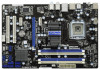
...Dual Core / Celeron®, supporting Penryn Quad Core Yorkfield and Dual Core Wolfdale processors - Supports Untied Overclocking Technology (see CAUTION 6) 6 Northbridge: Intel® P43 - Supports Intel® Extreme Memory Profile (XMP) - 1 x PCI Express 2.0 x16 slot (blue @ x16 mode) - 2 x PCI Express x1 slots... - 1 x PS/2 Keyboard Port - 1 x Coaxial SPDIF Out Port - 1 x Optical SPDIF Out Port - 5 x Ready-to-Use USB 2.0 Ports - 1 x eSATAII Port - 1 x Ready-to-Use USB 3.0 Port - 1 x RJ-45 LAN Port with Content Protection (Realtek ALC892 Audio Codec) - Premium Blu-ray audio support -
...Dual Core / Celeron®, supporting Penryn Quad Core Yorkfield and Dual Core Wolfdale processors - Supports Untied Overclocking Technology (see CAUTION 6) 6 Northbridge: Intel® P43 - Supports Intel® Extreme Memory Profile (XMP) - 1 x PCI Express 2.0 x16 slot (blue @ x16 mode) - 2 x PCI Express x1 slots... - 1 x PS/2 Keyboard Port - 1 x Coaxial SPDIF Out Port - 1 x Optical SPDIF Out Port - 5 x Ready-to-Use USB 2.0 Ports - 1 x eSATAII Port - 1 x Ready-to-Use USB 3.0 Port - 1 x RJ-45 LAN Port with Content Protection (Realtek ALC892 Audio Codec) - Premium Blu-ray audio support -
User Manual
Page 9
...frequencies may cause the instability of the system or damage the CPU. 13. ASRock website: http://www.asrock.com 10. OC DNA literally tells you install the PC system. 14. According to your USB flash drive, floppy disk or hard drive, then you can save your friends!... and share with the power supply manufacturer for the operation procedures of . EuP, stands for Energy Using Product, was a provision regulated by ASRock, provides a convenient way for the completed system. With this utility, you checking with your overclocking record under 1.00W in Flash ROM. For...
...frequencies may cause the instability of the system or damage the CPU. 13. ASRock website: http://www.asrock.com 10. OC DNA literally tells you install the PC system. 14. According to your USB flash drive, floppy disk or hard drive, then you can save your friends!... and share with the power supply manufacturer for the operation procedures of . EuP, stands for Energy Using Product, was a provision regulated by ASRock, provides a convenient way for the completed system. With this utility, you checking with your overclocking record under 1.00W in Flash ROM. For...

User Manual
Page 10
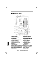
...Dual Channel 34 USB_PWR2 1 USB 2.0 T: USB0 B: USB1 USB 2.0 T: USB2 B: USB3 7 DDR3_B1 (64 bit, 240-pin module) DDR3_B2 (64 bit, 240-pin module) AT X P W R 1 DDR3_A2 (64 bit, 240-pin module) DDR3_A1 (64 bit, 240-pin module) RJ-45 USB 2.0: USB4 eSATAII1 USB 3.0: USB5 P43 Pro/USB3 FSB1600 33 Top: SIDE ...SPK Center: REAR SPK Bottom: CTR BASS Intel P43 8 Top: LINE IN Center: FRONT Bottom: MIC IN Chipset CHA_FAN1 30.5cm (12.0 in) 32 ...
...Dual Channel 34 USB_PWR2 1 USB 2.0 T: USB0 B: USB1 USB 2.0 T: USB2 B: USB3 7 DDR3_B1 (64 bit, 240-pin module) DDR3_B2 (64 bit, 240-pin module) AT X P W R 1 DDR3_A2 (64 bit, 240-pin module) DDR3_A1 (64 bit, 240-pin module) RJ-45 USB 2.0: USB4 eSATAII1 USB 3.0: USB5 P43 Pro/USB3 FSB1600 33 Top: SIDE ...SPK Center: REAR SPK Bottom: CTR BASS Intel P43 8 Top: LINE IN Center: FRONT Bottom: MIC IN Chipset CHA_FAN1 30.5cm (12.0 in) 32 ...

User Manual
Page 11
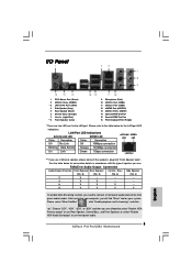
... or "8CH" and then you are two LED next to the LAN port. 1 . 4 I/O Panel 1 2 3 4 7 5 8 6 9 16 15 14 1 PS/2 Mouse Port (Green) 2 USB 2.0 Ports (USB23) * 3 LAN RJ-45 Port (LAN1) 4 Side Speaker (Gray) 5 Rear Speaker (Black) 6 Central / Bass (Orange) 7 Line In (Light Blue) ** 8 Front Speaker (Lime)... 13 12 11 10 9 Microphone (Pink) 10 USB 2.0 Port (USB4) 11 USB 3.0 Port (USB5) 12 eSATAII Port (eSATAII1) 13 USB 2.0 Ports (USB01) 14 Optical SPDIF Out Port 15 Coaxial SPDIF Out Port 16 PS/2 Keyboard Port (Purple) * There are...
... or "8CH" and then you are two LED next to the LAN port. 1 . 4 I/O Panel 1 2 3 4 7 5 8 6 9 16 15 14 1 PS/2 Mouse Port (Green) 2 USB 2.0 Ports (USB23) * 3 LAN RJ-45 Port (LAN1) 4 Side Speaker (Gray) 5 Rear Speaker (Black) 6 Central / Bass (Orange) 7 Line In (Light Blue) ** 8 Front Speaker (Lime)... 13 12 11 10 9 Microphone (Pink) 10 USB 2.0 Port (USB4) 11 USB 3.0 Port (USB5) 12 eSATAII Port (eSATAII1) 13 USB 2.0 Ports (USB01) 14 Optical SPDIF Out Port 15 Coaxial SPDIF Out Port 16 PS/2 Keyboard Port (Purple) * There are...

User Manual
Page 19
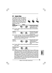
... higher standby current provided by power supply. Note: To select +5VSB, it down before you do not clear the CMOS right after you select +5V_DUAL, USB devices can wake up events. USB_PW2 1_2 Short pin2, pin3 to enable (see p.10, No. 34) +5V_DUAL for USB23/45 +5V +5V_DUAL wake up events...
... higher standby current provided by power supply. Note: To select +5VSB, it down before you do not clear the CMOS right after you select +5V_DUAL, USB devices can wake up events. USB_PW2 1_2 Short pin2, pin3 to enable (see p.10, No. 34) +5V_DUAL for USB23/45 +5V +5V_DUAL wake up events...

User Manual
Page 20
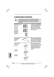
...Port 2) SATAII_1 (Port 0) SATAII_5 (Port 4) SATAII_4 (Port 3) SATAII_2 (Port 1) 2.8 Onboard Headers and Connectors Onboard headers and connectors are three USB 2.0 headers on this motherboard. Placing jumper caps over these headers and connectors. Serial ATAII Connectors (SATAII_1 (Port 0): see p.10, No. 12) ... GND DUMMY 1 GND P+8 P-8 USB_PWR USB_PWR P-7 P+7 GND DUMMY 1 GND P+6 P-6 USB_PWR Either end of the motherboard! Serial ATA (SATA) Data Cable (Optional) USB 2.0 Headers (9-pin USB10_11) (see p.10 No. 21) (9-pin USB8_9) (see p.10 No. 18) (9-pin USB6_7) (see p.10, No. 16) These five...
...Port 2) SATAII_1 (Port 0) SATAII_5 (Port 4) SATAII_4 (Port 3) SATAII_2 (Port 1) 2.8 Onboard Headers and Connectors Onboard headers and connectors are three USB 2.0 headers on this motherboard. Placing jumper caps over these headers and connectors. Serial ATAII Connectors (SATAII_1 (Port 0): see p.10, No. 12) ... GND DUMMY 1 GND P+8 P-8 USB_PWR USB_PWR P-7 P+7 GND DUMMY 1 GND P+6 P-6 USB_PWR Either end of the motherboard! Serial ATA (SATA) Data Cable (Optional) USB 2.0 Headers (9-pin USB10_11) (see p.10 No. 21) (9-pin USB8_9) (see p.10 No. 18) (9-pin USB6_7) (see p.10, No. 16) These five...

User Manual
Page 37
... wrong values in below sections may set the configurations for CPU CPU Configuration Chipset Configuration ACPI Configuration Storage Configuration PCIPnP Configuration SuperIO Configuration USB Configuration BIOS Update Utility ASRock Instant Flash Select Screen Select Item Enter Go to update system BIOS without preparing an additional floppy diskette or other complicated flash utility...
... wrong values in below sections may set the configurations for CPU CPU Configuration Chipset Configuration ACPI Configuration Storage Configuration PCIPnP Configuration SuperIO Configuration USB Configuration BIOS Update Utility ASRock Instant Flash Select Screen Select Item Enter Go to update system BIOS without preparing an additional floppy diskette or other complicated flash utility...
User Manual
Page 48
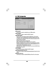
... configuration options: [Enabled], [Auto], [Disabled] and [BIOS Setup Only]. USB Mouse Power On Use this item to select legacy support for USB devices. 3.4.7 USB Configuration BIOS SETUP UTILITY Advanced USB Configuration USB Controller USB 2.0 Support Legacy USB Support USB 3.0 Support [Enabled] [Enabled] [Enabled] [Enabled] USB Keyboard/Remote Power On [Disabled] USB Mouse Power On [Disabled] To enable or disable the...
... configuration options: [Enabled], [Auto], [Disabled] and [BIOS Setup Only]. USB Mouse Power On Use this item to select legacy support for USB devices. 3.4.7 USB Configuration BIOS SETUP UTILITY Advanced USB Configuration USB Controller USB 2.0 Support Legacy USB Support USB 3.0 Support [Enabled] [Enabled] [Enabled] [Enabled] USB Keyboard/Remote Power On [Disabled] USB Mouse Power On [Disabled] To enable or disable the...
Quick Installation Guide
Page 2
...) ) 32 Power Fan Connector (PWR_FAN1) 16 Fifth SATAII Connector (SATAII_5 (Port 4), Blue) 33 North Bridge Controller 17 USB_PWR3 Jumper 34 USB_PWR2 Jumper 18 USB 2.0 Header (USB8_9, Blue) 2 ASRock P43 Pro/USB3 Motherboard Motherboard Layout English 1 PS2_USB_PWR1 Jumper 19 USB 2.0 Header (USB6_7, Blue) 2 ATX 12V Connector (ATX12V1) 20 Power LED Header (PLED1) 3 CPU Fan Connector (CPU_FAN1) 21...
...) ) 32 Power Fan Connector (PWR_FAN1) 16 Fifth SATAII Connector (SATAII_5 (Port 4), Blue) 33 North Bridge Controller 17 USB_PWR3 Jumper 34 USB_PWR2 Jumper 18 USB 2.0 Header (USB8_9, Blue) 2 ASRock P43 Pro/USB3 Motherboard Motherboard Layout English 1 PS2_USB_PWR1 Jumper 19 USB 2.0 Header (USB6_7, Blue) 2 ATX 12V Connector (ATX12V1) 20 Power LED Header (PLED1) 3 CPU Fan Connector (CPU_FAN1) 21...
Quick Installation Guide
Page 3
...computer, you need to connect a front panel audio cable to the front panel audio header. After restarting your system. I/O Panel 1 PS/2 Mouse Port (Green) 2 USB 2.0 Ports (USB23) * 3 LAN RJ-45 Port (LAN1) 4 Side Speaker (Gray) 5 Rear Speaker (Black) 6 Central / Bass (Orange) 7 Line In ...USB 2.0 Ports (USB01) 14 Optical SPDIF Out Port 15 Coaxial SPDIF Out Port 16 PS/2 Keyboard Port (Purple) * There are allowed to select "Realtek HDA Primary output" to use Rear Speaker, Central/Bass, and Front Speaker, or select "Realtek HDA Audio 2nd output" to use front panel audio. 3 ASRock P43 Pro/USB3...
...computer, you need to connect a front panel audio cable to the front panel audio header. After restarting your system. I/O Panel 1 PS/2 Mouse Port (Green) 2 USB 2.0 Ports (USB23) * 3 LAN RJ-45 Port (LAN1) 4 Side Speaker (Gray) 5 Rear Speaker (Black) 6 Central / Bass (Orange) 7 Line In ...USB 2.0 Ports (USB01) 14 Optical SPDIF Out Port 15 Coaxial SPDIF Out Port 16 PS/2 Keyboard Port (Purple) * There are allowed to select "Realtek HDA Primary output" to use Rear Speaker, Central/Bass, and Front Speaker, or select "Realtek HDA Audio 2nd output" to use front panel audio. 3 ASRock P43 Pro/USB3...

Quick Installation Guide
Page 5
... I /O Panel - 1 x PS/2 Mouse Port - 1 x PS/2 Keyboard Port - 1 x Coaxial SPDIF Out Port - 1 x Optical SPDIF Out Port - 5 x Ready-to-Use USB 2.0 Ports - 1 x eSATAII Port - 1 x Ready-to-Use USB 3.0 Port - 1 x RJ-45 LAN Port with Content Protection (Realtek ALC892 Audio Codec) - LGA 775 for Intel® CoreTM 2 Extreme / CoreTM 2 Quad / CoreTM... x 8.0-in /Front Speaker/Microphone (see CAUTION 3) - 4 x DDR3 DIMM slots - Supports FSB1600/1333/1066/800 MHz - Dual Channel DDR3 Memory Technology (see CAUTION 6) 5 ASRock P43 Pro/USB3 Motherboard English Max. Premium Blu-ray audio support -
... I /O Panel - 1 x PS/2 Mouse Port - 1 x PS/2 Keyboard Port - 1 x Coaxial SPDIF Out Port - 1 x Optical SPDIF Out Port - 5 x Ready-to-Use USB 2.0 Ports - 1 x eSATAII Port - 1 x Ready-to-Use USB 3.0 Port - 1 x RJ-45 LAN Port with Content Protection (Realtek ALC892 Audio Codec) - LGA 775 for Intel® CoreTM 2 Extreme / CoreTM 2 Quad / CoreTM... x 8.0-in /Front Speaker/Microphone (see CAUTION 3) - 4 x DDR3 DIMM slots - Supports FSB1600/1333/1066/800 MHz - Dual Channel DDR3 Memory Technology (see CAUTION 6) 5 ASRock P43 Pro/USB3 Motherboard English Max. Premium Blu-ray audio support -

Quick Installation Guide
Page 8
...computing performance. OC DNA literally tells you can only be noted that delivers unparalleled power savings. It helps you to your USB flash drive, floppy disk or hard drive, then you what it is a BIOS flash utility embedded in off mode condition... and simplifies the complicated recording process of . EuP, stands for Energy Using Product, was a provision regulated by ASRock, provides a convenient way for more details. 8 ASRock P43 Pro/USB3 Motherboard English Please visit our website for the completed system. According to perform over-clocking. 9. With this motherboard...
...computing performance. OC DNA literally tells you can only be noted that delivers unparalleled power savings. It helps you to your USB flash drive, floppy disk or hard drive, then you what it is a BIOS flash utility embedded in off mode condition... and simplifies the complicated recording process of . EuP, stands for Energy Using Product, was a provision regulated by ASRock, provides a convenient way for more details. 8 ASRock P43 Pro/USB3 Motherboard English Please visit our website for the completed system. According to perform over-clocking. 9. With this motherboard...
Quick Installation Guide
Page 15
The data in CMOS. However, please do the clear-CMOS action. 15 ASRock P43 Pro/USB3 Motherboard English Clear CMOS Jumper (CLRCMOS1) (see p.2, No. 9) Default Clear CMOS Note: CLRCMOS1 allows you select +5V_DUAL, USB devices can wake up the system under S3 (Suspend to enable (see p.2, No. 17) +5VSB (standby) for 5 seconds. USB_PW2 Short pin2, pin3...
The data in CMOS. However, please do the clear-CMOS action. 15 ASRock P43 Pro/USB3 Motherboard English Clear CMOS Jumper (CLRCMOS1) (see p.2, No. 9) Default Clear CMOS Note: CLRCMOS1 allows you select +5V_DUAL, USB devices can wake up the system under S3 (Suspend to enable (see p.2, No. 17) +5VSB (standby) for 5 seconds. USB_PW2 Short pin2, pin3...
Quick Installation Guide
Page 16
... 4): see p.2 No. 19) Either end of the motherboard! English 16 ASRock P43 Pro/USB3 Motherboard Do NOT place jumper caps over the headers and connectors will cause permanent damage of the SATA data cable can support two USB 2.0 ports. Serial ATA (SATA) Data Cable (Optional) USB 2.0 Headers (9-pin USB10_11) (see p.2 No. 21) (9-pin USB8_9) (see p.2 No...
... 4): see p.2 No. 19) Either end of the motherboard! English 16 ASRock P43 Pro/USB3 Motherboard Do NOT place jumper caps over the headers and connectors will cause permanent damage of the SATA data cable can support two USB 2.0 ports. Serial ATA (SATA) Data Cable (Optional) USB 2.0 Headers (9-pin USB10_11) (see p.2 No. 21) (9-pin USB8_9) (see p.2 No...


