User Manual
Page 3
...Motherboard Layout 10 1.4 I/O Panel 11 2 Installation 12 2.1 Screw Holes 12 2.2 Pre-installation Precautions 12 2.3 CPU Installation 13 2.4 Installation of Heatsink and CPU fan 15 2.5 Installation of Memory Modules (DIMM 16 2.6 Expansion Slots (PCI and PCI Express Slots 18 2.7 Jumpers Setup 19 2.8 Onboard Headers and Connectors 20 2.9 SATAII Hard Disk Setup Guide 24 2.10 Serial ATA (SATA) / Serial ATAII (SATAII) Hard Disks Installation 25 2.11 Hot Plug Function for SATA / SATAII HDDs 25 2.12 SATA / SATAII HDD Hot Plug Feature and Operation Guide 26 2.13 Driver Installation Guide...
...Motherboard Layout 10 1.4 I/O Panel 11 2 Installation 12 2.1 Screw Holes 12 2.2 Pre-installation Precautions 12 2.3 CPU Installation 13 2.4 Installation of Heatsink and CPU fan 15 2.5 Installation of Memory Modules (DIMM 16 2.6 Expansion Slots (PCI and PCI Express Slots 18 2.7 Jumpers Setup 19 2.8 Onboard Headers and Connectors 20 2.9 SATAII Hard Disk Setup Guide 24 2.10 Serial ATA (SATA) / Serial ATAII (SATAII) Hard Disks Installation 25 2.11 Hot Plug Function for SATA / SATAII HDDs 25 2.12 SATA / SATAII HDD Hot Plug Feature and Operation Guide 26 2.13 Driver Installation Guide...
User Manual
Page 9
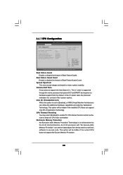
... heatsink when you resume the system, please check if the CPU fan on the same motherboard. 12. While CPU overheat is a revolutionary technology that the USB flash drive or hard drive must meet EuP standard, an EuP ready motherboard and an EuP ready power supply are required. According to update system BIOS without preparing an additional floppy diskette or other words, it is higher than the recommended CPU bus frequencies...
... heatsink when you resume the system, please check if the CPU fan on the same motherboard. 12. While CPU overheat is a revolutionary technology that the USB flash drive or hard drive must meet EuP standard, an EuP ready motherboard and an EuP ready power supply are required. According to update system BIOS without preparing an additional floppy diskette or other words, it is higher than the recommended CPU bus frequencies...

User Manual
Page 10
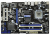
White) 25 HDMI_SPDIF Header 7 ATX Power Connector (ATXPWR1) (HDMI_SPDIF1, White) 8 Chassis Fan Connector (CHA_FAN1) 26 Infrared Module Header (IR1) 9 Clear CMOS Jumper (CLRCMOS1) 27 Front Panel Audio Header 10 SPI BIOS Chip (HD_AUDIO1, White) 11 South Bridge Controller 28 PCI Slots (PCI1 - 2) 12 Primary SATAII Connector (SATAII_1 (Port 0), Blue) 29 PCI Express x1 Slot (PCIE3, White) 13 Secondary SATAII Connector (SATAII_2 (Port 1), Blue) 30 PCI Express 2.0 x16 Slot (PCIE2, Blue) 14 Third SATAII Connector (SATAII_3 (Port 2), Blue) 31 PCI Express x1 Slot (PCIE1, White) 15...
White) 25 HDMI_SPDIF Header 7 ATX Power Connector (ATXPWR1) (HDMI_SPDIF1, White) 8 Chassis Fan Connector (CHA_FAN1) 26 Infrared Module Header (IR1) 9 Clear CMOS Jumper (CLRCMOS1) 27 Front Panel Audio Header 10 SPI BIOS Chip (HD_AUDIO1, White) 11 South Bridge Controller 28 PCI Slots (PCI1 - 2) 12 Primary SATAII Connector (SATAII_1 (Port 0), Blue) 29 PCI Express x1 Slot (PCIE3, White) 13 Secondary SATAII Connector (SATAII_2 (Port 1), Blue) 30 PCI Express 2.0 x16 Slot (PCIE2, Blue) 14 Third SATAII Connector (SATAII_3 (Port 2), Blue) 31 PCI Express x1 Slot (PCIE1, White) 15...
User Manual
Page 28
... system boot-up to bottom side to install those required drivers. D. 2.13 Driver Installation Guide To install the drivers to your system, please insert the support CD to your system. Then, the drivers compatible to [AHCI]. Enter BIOS SETUP UTILITY Advanced screen Storage Configuration. B. Please select CD-ROM as ", please set the option to your SATA / SATAII HDDs without RAID functions, please follow below steps. STEP 2: Make a SATA / SATAII driver diskette. Therefore, the drivers you install can work properly. 2.14 Installing Windows...
... system boot-up to bottom side to install those required drivers. D. 2.13 Driver Installation Guide To install the drivers to your system, please insert the support CD to your system. Then, the drivers compatible to [AHCI]. Enter BIOS SETUP UTILITY Advanced screen Storage Configuration. B. Please select CD-ROM as ", please set the option to your SATA / SATAII HDDs without RAID functions, please follow below steps. STEP 2: Make a SATA / SATAII driver diskette. Therefore, the drivers you install can work properly. 2.14 Installing Windows...
User Manual
Page 38
... No-Execute Memory Protection Intel (R) SpeedStep (tm) tech. [Disabled] [Enabled] [Enabled] [Disabled] [Auto] Enable or disable the feature of Boot Failure Guard. Spread Spectrum This item should always be hidden if the installed CPU does not support Intel (R) Virtualization Technology. An IA-32 processor with "No Execute (NX) Memory Protection" can utilize the additional hardware capabilities provided by malicious software to keep the CPU from being used by Vanderpool Technology. The C1...
... No-Execute Memory Protection Intel (R) SpeedStep (tm) tech. [Disabled] [Enabled] [Enabled] [Disabled] [Auto] Enable or disable the feature of Boot Failure Guard. Spread Spectrum This item should always be hidden if the installed CPU does not support Intel (R) Virtualization Technology. An IA-32 processor with "No Execute (NX) Memory Protection" can utilize the additional hardware capabilities provided by malicious software to keep the CPU from being used by Vanderpool Technology. The C1...
User Manual
Page 43
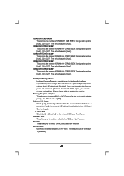
... default value is [Auto]. The default value is [Auto]. Configuration options: [Auto], [Enabled] and [Disabled]. DRAM CH1 CTRL1 SKEW This controls the number of DRAM CH1 CTRL2 SKEW. DRAM CH1 CMD SKEW This controls the number of this feature is [Auto]. Dr. LAN This allows you can also choose our Intelligent Energy Saver utility to enable this item to select [PCI] or [PCI Express] as the boot graphic adapter priority. CIR10 Field 1 Use this...
... default value is [Auto]. The default value is [Auto]. Configuration options: [Auto], [Enabled] and [Disabled]. DRAM CH1 CTRL1 SKEW This controls the number of DRAM CH1 CTRL2 SKEW. DRAM CH1 CMD SKEW This controls the number of this feature is [Auto]. Dr. LAN This allows you can also choose our Intelligent Energy Saver utility to enable this item to select [PCI] or [PCI Express] as the boot graphic adapter priority. CIR10 Field 1 Use this...
User Manual
Page 46
... Installed]: Select [Not Installed] to disable the use a disk utility, such as MO. S.M.A.R.T. The default value is used for Netware and UNIX user, select [Disabled] to disable the LBA/Large mode. After selecting the hard disk information into BIOS, use of this item to enable or disable the S.M.A.R.T. (Self-Monitoring, Analysis, and Reporting Technology) feature. for IDE ARMD (ATAPI Removable Media Device), such as FDISK, to partition and format the new IDE hard disk drives. Configuration options: [Disabled], [Auto], [Enabled]. 32-Bit Data...
... Installed]: Select [Not Installed] to disable the use a disk utility, such as MO. S.M.A.R.T. The default value is used for Netware and UNIX user, select [Disabled] to disable the LBA/Large mode. After selecting the hard disk information into BIOS, use of this item to enable or disable the S.M.A.R.T. (Self-Monitoring, Analysis, and Reporting Technology) feature. for IDE ARMD (ATAPI Removable Media Device), such as FDISK, to partition and format the new IDE hard disk drives. Configuration options: [Disabled], [Auto], [Enabled]. 32-Bit Data...
User Manual
Page 47
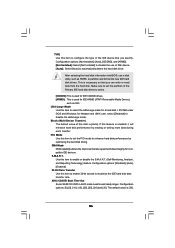
... Select Screen Select Item Change Option General Help Load Defaults Save and Exit Exit v02.54 (C) Copyright 1985-2005, American Megatrends, Inc. PCI IDE BusMaster Use this item to keep the default value unless the installed PCI expansion cards' specifications require other settings. Configuration options: [Disabled], [3F8 / IRQ4], [2F8 / IRQ3], [3E8 / IRQ4], [2E8 / IRQ3]. Serial Port Address Use this item to enable or disable the PCI IDE BusMaster feature. 3.4.6 Super IO Configuration BIOS SETUP UTILITY Advanced Configure Super IO Chipset Serial Port...
... Select Screen Select Item Change Option General Help Load Defaults Save and Exit Exit v02.54 (C) Copyright 1985-2005, American Megatrends, Inc. PCI IDE BusMaster Use this item to keep the default value unless the installed PCI expansion cards' specifications require other settings. Configuration options: [Disabled], [3F8 / IRQ4], [2F8 / IRQ3], [3E8 / IRQ4], [2E8 / IRQ3]. Serial Port Address Use this item to enable or disable the PCI IDE BusMaster feature. 3.4.6 Super IO Configuration BIOS SETUP UTILITY Advanced Configure Super IO Chipset Serial Port...
User Manual
Page 48
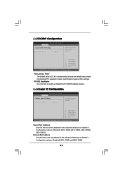
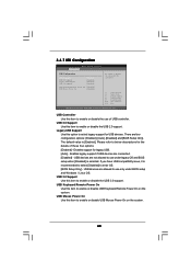
...legacy support for legacy USB. [Auto] - USB 3.0 Support Use this item to enable or disable the USB 3.0 support. Legacy USB Support Use this item to below descriptions for the details of USB controller. 3.4.7 USB Configuration BIOS SETUP UTILITY Advanced USB Configuration USB Controller USB 2.0 Support Legacy USB Support USB 3.0 Support [Enabled] [Enabled] [Enabled] [Enabled] USB Keyboard/Remote Power On [Disabled] USB Mouse Power On [Disabled] To enable or disable the onboard USB controllers. +F1 F9 F10 ESC Select Screen Select Item Change Option General Help Load Defaults...
...legacy support for legacy USB. [Auto] - USB 3.0 Support Use this item to enable or disable the USB 3.0 support. Legacy USB Support Use this item to below descriptions for the details of USB controller. 3.4.7 USB Configuration BIOS SETUP UTILITY Advanced USB Configuration USB Controller USB 2.0 Support Legacy USB Support USB 3.0 Support [Enabled] [Enabled] [Enabled] [Enabled] USB Keyboard/Remote Power On [Disabled] USB Mouse Power On [Disabled] To enable or disable the onboard USB controllers. +F1 F9 F10 ESC Select Screen Select Item Change Option General Help Load Defaults...
User Manual
Page 51
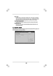
...". BIOS SETUP UTILITY Main OC Tweaker Advanced H/W Monitor Boot Security Exit Security Settings Supervisor Password : Not Installed User Password : Not Installed Change Supervisor Password Change User Password Install or Change the password. The default value is set or change the supervisor/user password for the system. Select Screen Select Item Enter Change F1 General Help F9 Load Defaults F10 Save and Exit ESC Exit v02.54 (C) Copyright 1985-2005, American Megatrends, Inc. 51 Boot Logo Use this item to enable or disable the Boot From Onboard LAN...
...". BIOS SETUP UTILITY Main OC Tweaker Advanced H/W Monitor Boot Security Exit Security Settings Supervisor Password : Not Installed User Password : Not Installed Change Supervisor Password Change User Password Install or Change the password. The default value is set or change the supervisor/user password for the system. Select Screen Select Item Enter Change F1 General Help F9 Load Defaults F10 Save and Exit ESC Exit v02.54 (C) Copyright 1985-2005, American Megatrends, Inc. 51 Boot Logo Use this item to enable or disable the Boot From Onboard LAN...
User Manual
Page 53
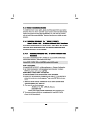
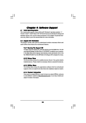
...; Windows® operating systems: 7 / 7 64-bit / VistaTM / VistaTM 64-bit / XP / XP 64-bit. Please install the necessary drivers to your CD-ROM drive. Refer to activate the devices. 4.2.3 Utilities Menu The Utilities Menu shows the applications software that enhance the motherboard features. 4.2.1 Running The Support CD To begin using the support CD, insert the CD into your OS documentation for general reference only. Because motherboard settings and hardware options vary, use...
...; Windows® operating systems: 7 / 7 64-bit / VistaTM / VistaTM 64-bit / XP / XP 64-bit. Please install the necessary drivers to your CD-ROM drive. Refer to activate the devices. 4.2.3 Utilities Menu The Utilities Menu shows the applications software that enhance the motherboard features. 4.2.1 Running The Support CD To begin using the support CD, insert the CD into your OS documentation for general reference only. Because motherboard settings and hardware options vary, use...
Quick Installation Guide
Page 2
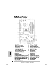
... 17 USB_PWR3 Jumper 34 USB_PWR2 Jumper 18 USB 2.0 Header (USB8_9, Blue) 2 ASRock P43 Pro/USB3 Motherboard Motherboard Layout English 1 PS2_USB_PWR1 Jumper 19 USB 2.0 Header (USB6_7, Blue) 2 ATX 12V Connector (ATX12V1) 20 Power LED Header (PLED1) 3 CPU Fan Connector (CPU_FAN1) 21 USB 2.0 Header (USB10_11, Blue) 4 775-Pin CPU Socket 22 System Panel Header (PANEL1, White) 5 2 x 240-pin DDR3 DIMM Slots 23 Chassis Speaker Header (Dual Channel: DDR3_A1, DDR3_B1; Blue) (SPEAKER 1, White) 6 2 x 240-pin DDR3 DIMM Slots 24 COM Port Header (COM1) (Dual Channel: DDR3_A2, DDR3_B2...
... 17 USB_PWR3 Jumper 34 USB_PWR2 Jumper 18 USB 2.0 Header (USB8_9, Blue) 2 ASRock P43 Pro/USB3 Motherboard Motherboard Layout English 1 PS2_USB_PWR1 Jumper 19 USB 2.0 Header (USB6_7, Blue) 2 ATX 12V Connector (ATX12V1) 20 Power LED Header (PLED1) 3 CPU Fan Connector (CPU_FAN1) 21 USB 2.0 Header (USB10_11, Blue) 4 775-Pin CPU Socket 22 System Panel Header (PANEL1, White) 5 2 x 240-pin DDR3 DIMM Slots 23 Chassis Speaker Header (Dual Channel: DDR3_A1, DDR3_B1; Blue) (SPEAKER 1, White) 6 2 x 240-pin DDR3 DIMM Slots 24 COM Port Header (COM1) (Dual Channel: DDR3_A2, DDR3_B2...
Quick Installation Guide
Page 3
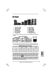
... (Orange) 7 Line In (Light Blue) ** 8 Front Speaker (Lime) 9 Microphone (Pink) 10 USB 2.0 Port (USB4) 11 USB 3.0 Port (USB5) 12 eSATAII Port (eSATAII1) 13 USB 2.0 Ports (USB01) 14 Optical SPDIF Out Port 15 Coaxial SPDIF Out Port 16 PS/2 Keyboard Port (Purple) * There are allowed to select "Realtek HDA Primary output" to use Rear Speaker, Central/Bass, and Front Speaker, or select "Realtek HDA Audio 2nd output" to use front panel audio. 3 ASRock P43 Pro/USB3 Motherboard English
... (Orange) 7 Line In (Light Blue) ** 8 Front Speaker (Lime) 9 Microphone (Pink) 10 USB 2.0 Port (USB4) 11 USB 3.0 Port (USB5) 12 eSATAII Port (eSATAII1) 13 USB 2.0 Ports (USB01) 14 Optical SPDIF Out Port 15 Coaxial SPDIF Out Port 16 PS/2 Keyboard Port (Purple) * There are allowed to select "Realtek HDA Primary output" to use Rear Speaker, Central/Bass, and Front Speaker, or select "Realtek HDA Audio 2nd output" to use front panel audio. 3 ASRock P43 Pro/USB3 Motherboard English
Quick Installation Guide
Page 4
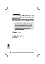
... be found in the user manual presented in , 30.5 cm x 20.3 cm) ASRock P43 Pro/USB3 Quick Installation Guide ASRock P43 Pro/USB3 Support CD Two Serial ATA (SATA) Data Cables (Optional) One I/O Panel Shield 4 ASRock P43 Pro/USB3 Motherboard English www.asrock.com/support/index.asp 1.1 Package Contents ASRock P43 Pro/USB3 Motherboard (ATX Form Factor: 12.0-in x 8.0-in the Support CD. Introduction Thank you are using. It delivers excellent performance with robust design conforming to ASRock's commitment to change without further notice. More...
... be found in the user manual presented in , 30.5 cm x 20.3 cm) ASRock P43 Pro/USB3 Quick Installation Guide ASRock P43 Pro/USB3 Support CD Two Serial ATA (SATA) Data Cables (Optional) One I/O Panel Shield 4 ASRock P43 Pro/USB3 Motherboard English www.asrock.com/support/index.asp 1.1 Package Contents ASRock P43 Pro/USB3 Motherboard (ATX Form Factor: 12.0-in x 8.0-in the Support CD. Introduction Thank you are using. It delivers excellent performance with robust design conforming to ASRock's commitment to change without further notice. More...
Quick Installation Guide
Page 7
... own risk and expense. Before you to the components and devices of "User Manual" in the BIOS, applying Untied Overclocking Technology, or using the thirdparty overclocking tools. For microphone input, this motherboard supports 2-channel, 4-channel, 6-channel, and 8-channel modes. You can also connect SATA hard disk to read the "SATAII Hard Disk Setup Guide" on page 12 for proper connection. 7. Certifications - Please check the table on page 21 for the CPU FSB frequency and its corresponding memory support frequency.
... own risk and expense. Before you to the components and devices of "User Manual" in the BIOS, applying Untied Overclocking Technology, or using the thirdparty overclocking tools. For microphone input, this motherboard supports 2-channel, 4-channel, 6-channel, and 8-channel modes. You can also connect SATA hard disk to read the "SATAII Hard Disk Setup Guide" on page 12 for proper connection. 7. Certifications - Please check the table on page 21 for the CPU FSB frequency and its corresponding memory support frequency.

Quick Installation Guide
Page 8
... other complicated flash utility. According to your USB flash drive, floppy disk or hard drive, then you can update your overclocking record under 1.00W in off mode condition. In other than 50% under 100 mA current consumption. Just launch this motherboard offers stepless control, it is not recommended to access ASRock Instant Flash. Please be noticed that delivers unparalleled power savings. While CPU overheat is capable of. The software name...
... other complicated flash utility. According to your USB flash drive, floppy disk or hard drive, then you can update your overclocking record under 1.00W in off mode condition. In other than 50% under 100 mA current consumption. Just launch this motherboard offers stepless control, it is not recommended to access ASRock Instant Flash. Please be noticed that delivers unparalleled power savings. While CPU overheat is capable of. The software name...
Quick Installation Guide
Page 12
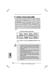
... color. Blue slots; Dual Channel Memory Configurations DDR3_A1 DDR3_A2 DDR3_B1 DDR3_B2 (Blue Slot) (White Slot) (Blue Slot) (White Slot) (1) Populated - In other words, you have to activate the Dual Channel Memory Technology. 3. English 12 ASRock P43 Pro/USB3 Motherboard Populated - If a pair of memory modules is NOT installed in the slots of the same color. If you adopt a DDR3 1600 memory module, you always need to install identical (the same brand, speed, size and chiptype...
... color. Blue slots; Dual Channel Memory Configurations DDR3_A1 DDR3_A2 DDR3_B1 DDR3_B2 (Blue Slot) (White Slot) (Blue Slot) (White Slot) (1) Populated - In other words, you have to activate the Dual Channel Memory Technology. 3. English 12 ASRock P43 Pro/USB3 Motherboard Populated - If a pair of memory modules is NOT installed in the slots of the same color. If you adopt a DDR3 1600 memory module, you always need to install identical (the same brand, speed, size and chiptype...
Quick Installation Guide
Page 18
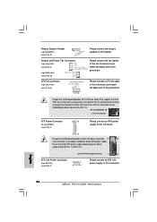
...Pin CPU fan (Quiet Fan) support, the 3-Pin CPU fan still can still work successfully even without the fan speed control function. Please connect a CPU fan cable to this connector and match the black wire to the ground pin. English 18 ASRock P43 Pro/USB3 Motherboard If you plan to connect the 3-Pin CPU fan to Pin 1-3. ATX 12V Power Connector (8-pin ATX12V1) (see p.2 No. 2) 20-Pin ATX Power Supply Installation 1 13 8 5 4 1 Please connect an ATX 12V power supply to this header. Chassis Speaker Header (4-pin SPEAKER 1) (see p.2 No. 23) Chassis and Power Fan Connectors...
...Pin CPU fan (Quiet Fan) support, the 3-Pin CPU fan still can still work successfully even without the fan speed control function. Please connect a CPU fan cable to this connector and match the black wire to the ground pin. English 18 ASRock P43 Pro/USB3 Motherboard If you plan to connect the 3-Pin CPU fan to Pin 1-3. ATX 12V Power Connector (8-pin ATX12V1) (see p.2 No. 2) 20-Pin ATX Power Supply Installation 1 13 8 5 4 1 Please connect an ATX 12V power supply to this header. Chassis Speaker Header (4-pin SPEAKER 1) (see p.2 No. 23) Chassis and Power Fan Connectors...

Quick Installation Guide
Page 20
... support CD driver page. Please follow the order from up BIOS. Enter BIOS SETUP UTILITY Advanced screen Storage Configuration. STEP 2: Install Windows® XP / XP 64-bit OS on your system. 2.8.2 Installing Windows® 7 / 7 64-bit / VistaTM / VistaTM 64-bit Without RAID Functions If you install can be auto-detected and listed on your system. 20 ASRock P43 Pro/USB3 Motherboard English Therefore, the drivers you want to install Windows® XP / XP 64-bit OS on your SATA / SATAII HDDs without RAID...
... support CD driver page. Please follow the order from up BIOS. Enter BIOS SETUP UTILITY Advanced screen Storage Configuration. STEP 2: Install Windows® XP / XP 64-bit OS on your system. 2.8.2 Installing Windows® 7 / 7 64-bit / VistaTM / VistaTM 64-bit Without RAID Functions If you install can be auto-detected and listed on your system. 20 ASRock P43 Pro/USB3 Motherboard English Therefore, the drivers you want to install Windows® XP / XP 64-bit OS on your SATA / SATAII HDDs without RAID...
Quick Installation Guide
Page 22
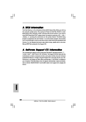
If you start up the computer, please press during the Power-On-Self-Test (POST) to enter BIOS Setup utility; The BIOS Setup program is a menu-driven program, which allows you to display the menus. 22 ASRock P43 Pro/USB3 Motherboard English BIOS Information The Flash Memory on the file "ASSETUP.EXE" from the BIN folder in the Support CD to scroll through its test routines. To begin using the Support CD, insert the...
If you start up the computer, please press during the Power-On-Self-Test (POST) to enter BIOS Setup utility; The BIOS Setup program is a menu-driven program, which allows you to display the menus. 22 ASRock P43 Pro/USB3 Motherboard English BIOS Information The Flash Memory on the file "ASSETUP.EXE" from the BIN folder in the Support CD to scroll through its test routines. To begin using the Support CD, insert the...


