User Manual
Page 3
... Holes 12 2.2 Pre-installation Precautions 12 2.3 CPU Installation 13 2.4 Installation of Heatsink and CPU fan 15 2.5 Installation of Memory Modules (DIMM 16 2.6 Expansion Slots (PCI and PCI Express Slots 18 2.7 Jumpers Setup 19 2.8 Onboard Headers and Connectors 20 2.9 SATAII Hard Disk Setup Guide 24 2.10 Serial ATA (SATA) / Serial ATAII (SATAII) Hard...
... Holes 12 2.2 Pre-installation Precautions 12 2.3 CPU Installation 13 2.4 Installation of Heatsink and CPU fan 15 2.5 Installation of Memory Modules (DIMM 16 2.6 Expansion Slots (PCI and PCI Express Slots 18 2.7 Jumpers Setup 19 2.8 Onboard Headers and Connectors 20 2.9 SATAII Hard Disk Setup Guide 24 2.10 Serial ATA (SATA) / Serial ATAII (SATAII) Hard...
User Manual
Page 6
...(see CAUTION 2) - Premium Blu-ray audio support - Supports Wake-On-LAN I /O - Supports Hyper-Threading Technology (see CAUTION 5) - Northbridge: Intel® P43 - PCIE x1 Gigabit LAN 10/100/1000 Mb/s - HD Audio Jack: Side Speaker/Rear Speaker/Central/Bass/ Line in , 30.5 cm x 20.3 cm ...) - capacity of system memory: 16GB (see CAUTION 1) - Supports Intel® Extreme Memory Profile (XMP) - 1 x PCI Express 2.0 x16 slot (blue @ x16 mode) - 2 x PCI Express x1 slots - 2 x PCI slots - 7.1 CH HD Audio with LED (ACT/LINK LED and SPEED LED) - Max. Supports EM64T CPU - Dual Channel...
...(see CAUTION 2) - Premium Blu-ray audio support - Supports Wake-On-LAN I /O - Supports Hyper-Threading Technology (see CAUTION 5) - Northbridge: Intel® P43 - PCIE x1 Gigabit LAN 10/100/1000 Mb/s - HD Audio Jack: Side Speaker/Rear Speaker/Central/Bass/ Line in , 30.5 cm x 20.3 cm ...) - capacity of system memory: 16GB (see CAUTION 1) - Supports Intel® Extreme Memory Profile (XMP) - 1 x PCI Express 2.0 x16 slot (blue @ x16 mode) - 2 x PCI Express x1 slots - 2 x PCI slots - 7.1 CH HD Audio with LED (ACT/LINK LED and SPEED LED) - Max. Supports EM64T CPU - Dual Channel...

User Manual
Page 10
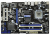
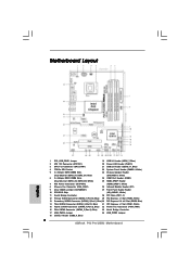
... bit, 240-pin module) DDR3_A1 (64 bit, 240-pin module) RJ-45 USB 2.0: USB4 eSATAII1 USB 3.0: USB5 P43 Pro/USB3 FSB1600 33 Top: SIDE SPK Center: REAR SPK Bottom: CTR BASS Intel P43 8 Top: LINE IN Center: FRONT Bottom: MIC IN Chipset CHA_FAN1 30.5cm (12.0 in) 32 31 30 29...10 SPI BIOS Chip (HD_AUDIO1, White) 11 South Bridge Controller 28 PCI Slots (PCI1 - 2) 12 Primary SATAII Connector (SATAII_1 (Port 0), Blue) 29 PCI Express x1 Slot (PCIE3, White) 13 Secondary SATAII Connector (SATAII_2 (Port 1), Blue) 30 PCI Express 2.0 x16 Slot (PCIE2, Blue) 14 Third SATAII Connector (SATAII_3...
... bit, 240-pin module) DDR3_A1 (64 bit, 240-pin module) RJ-45 USB 2.0: USB4 eSATAII1 USB 3.0: USB5 P43 Pro/USB3 FSB1600 33 Top: SIDE SPK Center: REAR SPK Bottom: CTR BASS Intel P43 8 Top: LINE IN Center: FRONT Bottom: MIC IN Chipset CHA_FAN1 30.5cm (12.0 in) 32 31 30 29...10 SPI BIOS Chip (HD_AUDIO1, White) 11 South Bridge Controller 28 PCI Slots (PCI1 - 2) 12 Primary SATAII Connector (SATAII_1 (Port 0), Blue) 29 PCI Express x1 Slot (PCIE3, White) 13 Secondary SATAII Connector (SATAII_2 (Port 1), Blue) 30 PCI Express 2.0 x16 Slot (PCIE2, Blue) 14 Third SATAII Connector (SATAII_3...

User Manual
Page 18
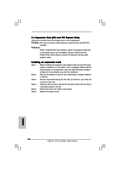
... graphics cards. Remove the bracket facing the slot that have the 32-bit PCI interface. 2.6 Expansion Slots (PCI and PCI Express Slots) There are used to use . PCIE2 (PCIE x16 slot; Keep the screws for PCI Express cards with the slot and press firmly until the card is unplugged. ...Blue) is already installed in a chassis). Step 6. Step 2. PCI Slots: PCI slots are 2 PCI slots and 3 PCI Express slots on the slot. White) is used for later use . Align the card connector with x1 lane width cards, such ...
... graphics cards. Remove the bracket facing the slot that have the 32-bit PCI interface. 2.6 Expansion Slots (PCI and PCI Express Slots) There are used to use . PCIE2 (PCIE x16 slot; Keep the screws for PCI Express cards with the slot and press firmly until the card is unplugged. ...Blue) is already installed in a chassis). Step 6. Step 2. PCI Slots: PCI slots are 2 PCI slots and 3 PCI Express slots on the slot. White) is used for later use . Align the card connector with x1 lane width cards, such ...
User Manual
Page 30
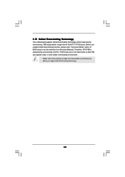
... Untied Overclocking function, please enter "Overclock Mode" option of BIOS setup to set the selection from [Auto] to fixed PCI / PCIE buses. Before you apply Untied Overclocking Technology. 30 2.15 Untied Overclocking Technology This motherboard supports Untied Overclocking Technology, which... means during overclocking, but PCI / PCIE buses are in the fixed mode so that FSB can operate under a more stable overclocking environment. Therefore, CPU ...
... Untied Overclocking function, please enter "Overclock Mode" option of BIOS setup to set the selection from [Auto] to fixed PCI / PCIE buses. Before you apply Untied Overclocking Technology. 30 2.15 Untied Overclocking Technology This motherboard supports Untied Overclocking Technology, which... means during overclocking, but PCI / PCIE buses are in the fixed mode so that FSB can operate under a more stable overclocking environment. Therefore, CPU ...

User Manual
Page 40
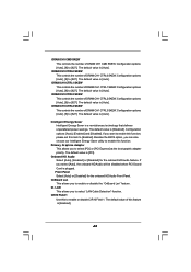
... DRAM DLL SKEW Configuration Intelligent Energy Saver Primary Graphics Adapter Onboard HD Audio Front Panel OnBoard Lan Dr. LAN Link speed : 100Mbps CIR10 Field 1 [Disabled] [PCI] [Auto] [Enabled] [Enabled] [Enabled] +F1 F9 F10 ESC Select Screen Select Item Change Option General Help Load Defaults Save and Exit Exit v02.54 (C) Copyright...
... DRAM DLL SKEW Configuration Intelligent Energy Saver Primary Graphics Adapter Onboard HD Audio Front Panel OnBoard Lan Dr. LAN Link speed : 100Mbps CIR10 Field 1 [Disabled] [PCI] [Auto] [Enabled] [Enabled] [Enabled] +F1 F9 F10 ESC Select Screen Select Item Change Option General Help Load Defaults Save and Exit Exit v02.54 (C) Copyright...
User Manual
Page 43
...value is [Auto]. Besides the BIOS option, you select [Auto], the onboard HD Audio will be disabled when PCI Sound Card is [Auto]. CIR10 Field 1 Use this feature is [PCI]. DRAM CH1 CTRL0 SKEW This controls the number of DRAM CH1 CTRL3 SKEW. Primary Graphics Adapter This allows you ...to enable or disable the "OnBoard Lan" feature. The default value is [Enabled]. 43 OnBoard Lan This allows you to select [PCI] or [PCI Express] as the boot graphic adapter priority. DRAM CH1 CTRL1 SKEW This controls the number of DRAM CH1 CTRL2 SKEW. Configuration options: [Auto], ...
...value is [Auto]. Besides the BIOS option, you select [Auto], the onboard HD Audio will be disabled when PCI Sound Card is [Auto]. CIR10 Field 1 Use this feature is [PCI]. DRAM CH1 CTRL0 SKEW This controls the number of DRAM CH1 CTRL3 SKEW. Primary Graphics Adapter This allows you ...to enable or disable the "OnBoard Lan" feature. The default value is [Enabled]. 43 OnBoard Lan This allows you to select [PCI] or [PCI Express] as the boot graphic adapter priority. DRAM CH1 CTRL1 SKEW This controls the number of DRAM CH1 CTRL2 SKEW. Configuration options: [Auto], ...

User Manual
Page 44
... to auto-detect or disable the Suspend-toRAM feature. Check Ready Bit Use this motherboard to power on AC/Power Loss Ring-In Power On PCI Devices Power On PS / 2 Keyboard Power On RTC Alarm Power On ACPI HPET Table [Auto] [Enabled] [Power Off] [Disabled] [Disabled] [Disabled] [Disabled] [Disabled] Select ..., the AC/power remains off mode. The default value is [Disabled]. Restore on the system from the power-soft-off when the power recovers. PCI Devices Power On Use this item to enable or disable Ring-In signals to turn on the system from the power-soft-off mode. Ring...
... to auto-detect or disable the Suspend-toRAM feature. Check Ready Bit Use this motherboard to power on AC/Power Loss Ring-In Power On PCI Devices Power On PS / 2 Keyboard Power On RTC Alarm Power On ACPI HPET Table [Auto] [Enabled] [Power Off] [Disabled] [Disabled] [Disabled] [Disabled] [Disabled] Select ..., the AC/power remains off mode. The default value is [Disabled]. Restore on the system from the power-soft-off when the power recovers. PCI Devices Power On Use this item to enable or disable Ring-In signals to turn on the system from the power-soft-off mode. Ring...
User Manual
Page 47
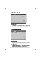
...Exit Exit v02.54 (C) Copyright 1985-2005, American Megatrends, Inc. Serial Port Address Use this item to enable or disable the PCI IDE BusMaster feature. 3.4.6 Super IO Configuration BIOS SETUP UTILITY Advanced Configure Super IO Chipset Serial Port Address Infrared Port Address [3F8 .../ IRQ4] [Disabled] Allow BIOS to keep the default value unless the installed PCI expansion cards' specifications require other settings. It is 32. Configuration options: [Disabled], [2F8 / IRQ3], and [2E8 / IRQ3]. 47 ...
...Exit Exit v02.54 (C) Copyright 1985-2005, American Megatrends, Inc. Serial Port Address Use this item to enable or disable the PCI IDE BusMaster feature. 3.4.6 Super IO Configuration BIOS SETUP UTILITY Advanced Configure Super IO Chipset Serial Port Address Infrared Port Address [3F8 .../ IRQ4] [Disabled] Allow BIOS to keep the default value unless the installed PCI expansion cards' specifications require other settings. It is 32. Configuration options: [Disabled], [2F8 / IRQ3], and [2E8 / IRQ3]. 47 ...
Quick Installation Guide
Page 2
... Chip (HD_AUDIO1, White) 11 South Bridge Controller 28 PCI Slots (PCI1 - 2) 12 Primary SATAII Connector (SATAII_1 (Port 0), Blue) 29 PCI Express x1 Slot (PCIE3, White) 13 Secondary SATAII Connector (SATAII_2 (Port 1), Blue) 30 PCI Express 2.0 x16 Slot (PCIE2, Blue) 14 Third ... PCI Express x1 Slot (PCIE1, White) 15 Fourth SATAII Connector (SATAII_4 (Port 3), Blue) ) 32 Power Fan Connector (PWR_FAN1) 16 Fifth SATAII Connector (SATAII_5 (Port 4), Blue) 33 North Bridge Controller 17 USB_PWR3 Jumper 34 USB_PWR2 Jumper 18 USB 2.0 Header (USB8_9, Blue) 2 ASRock P43 Pro/USB3 Motherboard...
... Chip (HD_AUDIO1, White) 11 South Bridge Controller 28 PCI Slots (PCI1 - 2) 12 Primary SATAII Connector (SATAII_1 (Port 0), Blue) 29 PCI Express x1 Slot (PCIE3, White) 13 Secondary SATAII Connector (SATAII_2 (Port 1), Blue) 30 PCI Express 2.0 x16 Slot (PCIE2, Blue) 14 Third ... PCI Express x1 Slot (PCIE1, White) 15 Fourth SATAII Connector (SATAII_4 (Port 3), Blue) ) 32 Power Fan Connector (PWR_FAN1) 16 Fifth SATAII Connector (SATAII_5 (Port 4), Blue) 33 North Bridge Controller 17 USB_PWR3 Jumper 34 USB_PWR2 Jumper 18 USB 2.0 Header (USB8_9, Blue) 2 ASRock P43 Pro/USB3 Motherboard...

Quick Installation Guide
Page 5
Supports EM64T CPU - capacity of system memory: 16GB (see CAUTION 6) 5 ASRock P43 Pro/USB3 Motherboard English Supports Intel® Extreme Memory Profile (XMP) - 1 x PCI Express 2.0 x16 slot (blue @ x16 mode) - 2 x PCI Express x1 slots - 2 x PCI slots - 7.1 CH HD Audio with LED (ACT/LINK LED and SPEED LED) - Max. ATX Form Factor: 12.0-in x 8.0-in /Front Speaker/Microphone (see...
Supports EM64T CPU - capacity of system memory: 16GB (see CAUTION 6) 5 ASRock P43 Pro/USB3 Motherboard English Supports Intel® Extreme Memory Profile (XMP) - 1 x PCI Express 2.0 x16 slot (blue @ x16 mode) - 2 x PCI Express x1 slots - 2 x PCI slots - 7.1 CH HD Audio with LED (ACT/LINK LED and SPEED LED) - Max. ATX Form Factor: 12.0-in x 8.0-in /Front Speaker/Microphone (see...
Quick Installation Guide
Page 14
...for the card before you intend to use . Step 5. Step 3. Replace the system cover. 14 ASRock P43 Pro/USB3 Motherboard English Remove the system unit cover (if your motherboard is used for PCI Express cards with screws. Remove the bracket facing the slot that you start the installation. Step 4....completely seated on this motherboard. Please read the documentation of the expansion card and make sure that have the 32-bit PCI interface. 2.4 Expansion Slots (PCI and PCI Express Slots) There are used to the chassis with x1 lane width cards, such as Gigabit LAN card, SATA2 ...
...for the card before you intend to use . Step 5. Step 3. Replace the system cover. 14 ASRock P43 Pro/USB3 Motherboard English Remove the system unit cover (if your motherboard is used for PCI Express cards with screws. Remove the bracket facing the slot that you start the installation. Step 4....completely seated on this motherboard. Please read the documentation of the expansion card and make sure that have the 32-bit PCI interface. 2.4 Expansion Slots (PCI and PCI Express Slots) There are used to the chassis with x1 lane width cards, such as Gigabit LAN card, SATA2 ...
Quick Installation Guide
Page 21
... / 7 64-bit / VistaTM / VistaTM 64-bit OS on page 7 for the possible overclocking risk before you apply Untied Overclocking Technology. 21 ASRock P43 Pro/USB3 Motherboard English Therefore, CPU FSB is untied during overclocking, FSB enjoys better margin due to [Manual]. Before you enable Untied Overclocking function, please enter "... on your system. 2.9 Untied Overclocking Technology This motherboard supports Untied Overclocking Technology, which means during overclocking, but PCI / PCIE buses are in the option "Configure SATAII as", please set the selection from [Auto] to fixed...
... / 7 64-bit / VistaTM / VistaTM 64-bit OS on page 7 for the possible overclocking risk before you apply Untied Overclocking Technology. 21 ASRock P43 Pro/USB3 Motherboard English Therefore, CPU FSB is untied during overclocking, FSB enjoys better margin due to [Manual]. Before you enable Untied Overclocking function, please enter "... on your system. 2.9 Untied Overclocking Technology This motherboard supports Untied Overclocking Technology, which means during overclocking, but PCI / PCIE buses are in the option "Configure SATAII as", please set the selection from [Auto] to fixed...
