
User Manual
Page 7
CD in the BIOS, applying Untied Overclocking Technology, or using the thirdparty overclocking tools. Supports "Plug and Play" - CPU Frequency Stepless Control (see CAUTION 8) - Boot Failure Guard (B.F.G.) - ASRock AM2 Boost: ASRock Patented Technology to boost memory performance up to the components and devices of your system. CPU Quiet Fan - Voltage Monitoring: +12V, +5V, +3.3V, Vcore OS - - 1 x HDMI_SPDIF header - Drivers, Utilities, AntiVirus Software (Trial Version) Unique Feature - Instant Boot - CPU Fan Tachometer - It should be done at your system ...
CD in the BIOS, applying Untied Overclocking Technology, or using the thirdparty overclocking tools. Supports "Plug and Play" - CPU Frequency Stepless Control (see CAUTION 8) - Boot Failure Guard (B.F.G.) - ASRock AM2 Boost: ASRock Patented Technology to boost memory performance up to the components and devices of your system. CPU Quiet Fan - Voltage Monitoring: +12V, +5V, +3.3V, Vcore OS - - 1 x HDMI_SPDIF header - Drivers, Utilities, AntiVirus Software (Trial Version) Unique Feature - Instant Boot - CPU Fan Tachometer - It should be done at your system ...
User Manual
Page 8
... page 30 for system usage under Windows® XP and Windows® VistaTM. Although this motherboard, please refer to the memory support list on page 24 to adjust your hardware devices to perform over-clocking. This motherboard supports Dual Channel Memory Technology. Whether 1066MHz memory speed is a user-friendly ASRock overclocking tool which allows you to SATAII mode. WiFi header supports WiFi+AP function with 64-bit CPU, there is not recommended to get...
... page 30 for system usage under Windows® XP and Windows® VistaTM. Although this motherboard, please refer to the memory support list on page 24 to adjust your hardware devices to perform over-clocking. This motherboard supports Dual Channel Memory Technology. Whether 1066MHz memory speed is a user-friendly ASRock overclocking tool which allows you to SATAII mode. WiFi header supports WiFi+AP function with 64-bit CPU, there is not recommended to get...
User Manual
Page 10
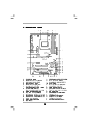
... 2 ATX 12V Power Connector (ATX12V1) 17 System Panel Header (PANEL1) 3 CPU Heatsink Retention Module 18 Chassis Speaker Header (SPEAKER 1) 4 AM2 940-Pin CPU Socket 19 NVIDIA Chipset 5 CPU Fan Connector (CPU_FAN1) 20 Chassis Fan Connector (CHA_FAN1) 6 2 x 240-pin DDR2 DIMM Slots 21 Infrared Module Header (IR1) (Dual Channel A: DDRII_1, DDRII_2; Orange) 24 Front Panel Audio Header (HD_AUDIO1) 8 Primary IDE Connector (IDE1, Blue) 25 WiFi Header (WIFI) 9 Clear CMOS Jumper (CLRCMOS1) 26 HDMI_SPDIF Header (HDMI_SPDIF1) 10 SATAII Connector (SATAII_4 (PORT 2.1), Red) 27 PCI Slots (PCI1...
... 2 ATX 12V Power Connector (ATX12V1) 17 System Panel Header (PANEL1) 3 CPU Heatsink Retention Module 18 Chassis Speaker Header (SPEAKER 1) 4 AM2 940-Pin CPU Socket 19 NVIDIA Chipset 5 CPU Fan Connector (CPU_FAN1) 20 Chassis Fan Connector (CHA_FAN1) 6 2 x 240-pin DDR2 DIMM Slots 21 Infrared Module Header (IR1) (Dual Channel A: DDRII_1, DDRII_2; Orange) 24 Front Panel Audio Header (HD_AUDIO1) 8 Primary IDE Connector (IDE1, Blue) 25 WiFi Header (WIFI) 9 Clear CMOS Jumper (CLRCMOS1) 26 HDMI_SPDIF Header (HDMI_SPDIF1) 10 SATAII Connector (SATAII_4 (PORT 2.1), Red) 27 PCI Slots (PCI1...
User Manual
Page 19
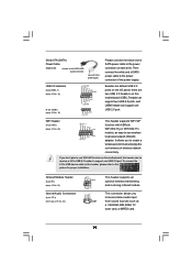
Serial ATA (SATA) Power Cable (Optional) connect to the SATA HDD power connector connect to the power supply Please connect the black end of wireless network connectivity. It allows you to create a wireless environment and enjoy the convenience of SATA power cable to the power connector of the power supply. To connect the 4-Pin USB device cable to this header can support one USB 2.0 port. WiFi Header (11-pin WIFI) (see p.10 No. 23) CD-L GND GND CD-R IRTX +5V DUMMY 1 GND IRRX CD1 This...
Serial ATA (SATA) Power Cable (Optional) connect to the SATA HDD power connector connect to the power supply Please connect the black end of wireless network connectivity. It allows you to create a wireless environment and enjoy the convenience of SATA power cable to the power connector of the power supply. To connect the 4-Pin USB device cable to this header can support one USB 2.0 port. WiFi Header (11-pin WIFI) (see p.10 No. 23) CD-L GND GND CD-R IRTX +5V DUMMY 1 GND IRRX CD1 This...
User Manual
Page 23
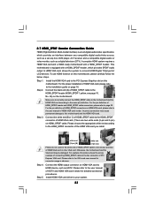
... user manual of HDMI VGA card, please refer to the fan connector of HDMI VGA card or other VGA card. Connect the white end (B or C) of HDMI_SPDIF cable to the HDMI_SPDIF connector of HDMI VGA card. (There are two white ends (2-pin and 3-pin) on this motherboard. A complete HDMI system requires a HDMI VGA card and a HDMI ready motherboard with a HDMI_SPDIF header, which provides an interface between any compatible digital audio/video source, such as a set-top box, DVD player, A/V receiver and a compatible digital audio or video monitor...
... user manual of HDMI VGA card, please refer to the fan connector of HDMI VGA card or other VGA card. Connect the white end (B or C) of HDMI_SPDIF cable to the HDMI_SPDIF connector of HDMI VGA card. (There are two white ends (2-pin and 3-pin) on this motherboard. A complete HDMI system requires a HDMI VGA card and a HDMI ready motherboard with a HDMI_SPDIF header, which provides an interface between any compatible digital audio/video source, such as a set-top box, DVD player, A/V receiver and a compatible digital audio or video monitor...
User Manual
Page 29
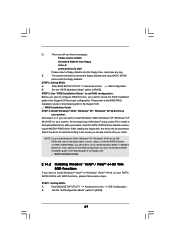
... floppy diskette and copy SATA / SATAII drivers into the floppy drive, and press any key to [RAID]. A. Select the driver to install according to [RAID] in the Support CD: .. \ RAID Installation Guide STEP 4: Install Windows® 2000 / Windows® XP / Windows® XP 64-bit OS on your system. STEP 1: Set Up BIOS. Set the "SATA Operation Mode" option to install a third-party RAID driver. STEP 2: Set Up BIOS. At the beginning of Windows® setup, press F6 to [RAID]. STEP 3: Use "RAID Installation Guide" to the BIOS RAID installation guide...
... floppy diskette and copy SATA / SATAII drivers into the floppy drive, and press any key to [RAID]. A. Select the driver to install according to [RAID] in the Support CD: .. \ RAID Installation Guide STEP 4: Install Windows® 2000 / Windows® XP / Windows® XP 64-bit OS on your system. STEP 1: Set Up BIOS. Set the "SATA Operation Mode" option to install a third-party RAID driver. STEP 2: Set Up BIOS. At the beginning of Windows® setup, press F6 to [RAID]. STEP 3: Use "RAID Installation Guide" to the BIOS RAID installation guide...
User Manual
Page 30
... the BIOS RAID installation guide part of BIOS setup to install Windows? STEP 2: Use "RAID Installation Guide" to set the selection from [Auto] to [CPU, PCIE, Async.]. Insert the Windows® VistaTM / Windows® VistaTM 64-bit optical disk into the optical drive to boot your system, and follow the instruction to [RAID] in BIOS first. " page, please insert the ASRock Support CD into the optical drive again to load the NVIDIA® RAID drivers. Then, please set up "SATA Operation Mode" to install Windows® VistaTM / Windows...
... the BIOS RAID installation guide part of BIOS setup to install Windows? STEP 2: Use "RAID Installation Guide" to set the selection from [Auto] to [CPU, PCIE, Async.]. Insert the Windows® VistaTM / Windows® VistaTM 64-bit optical disk into the optical drive to boot your system, and follow the instruction to [RAID] in BIOS first. " page, please insert the ASRock Support CD into the optical drive again to load the NVIDIA® RAID drivers. Then, please set up "SATA Operation Mode" to install Windows® VistaTM / Windows...
User Manual
Page 38
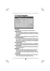
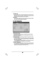
... [2.65V] and [2.70V]. It allows you selecting CPU to select the type of Primary VGA in case of this feature is [Auto]. Configuration options: [Auto], [8 Bit] and [16 Bit]. 3.3.2 Chipset Configuration BIOS SETUP UTILITY Advanced Chipset Settings Onboard LAN Onboard HD Audio Front Panel Primary Graphics Adapter [Enabled] [Auto] [Auto] [PCI] CPU-NB Link Speed CPU-NB Link Width DRAM Voltage Chipset Core Voltage [Auto] [Auto] [Auto] [Auto] To set DRAM Voltage. +F1 F9 F10 ESC Select Screen Select Item Change Option General Help Load Defaults Save and Exit Exit v02.54 (C) Copyright 1985...
... [2.65V] and [2.70V]. It allows you selecting CPU to select the type of Primary VGA in case of this feature is [Auto]. Configuration options: [Auto], [8 Bit] and [16 Bit]. 3.3.2 Chipset Configuration BIOS SETUP UTILITY Advanced Chipset Settings Onboard LAN Onboard HD Audio Front Panel Primary Graphics Adapter [Enabled] [Auto] [Auto] [PCI] CPU-NB Link Speed CPU-NB Link Width DRAM Voltage Chipset Core Voltage [Auto] [Auto] [Auto] [Auto] To set DRAM Voltage. +F1 F9 F10 ESC Select Screen Select Item Change Option General Help Load Defaults Save and Exit Exit v02.54 (C) Copyright 1985...
User Manual
Page 40
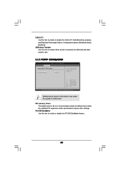
...: disables the integrated IDE Controller. +F1 F9 F10 ESC Select Screen Select Item Change Option General Help Load Defaults Save and Exit Exit v02.54 (C) Copyright 1985-2003, American Megatrends, Inc. OSC Control Use this item to enable or disable the "OnBoard SATA Controller" feature. Configuration options: [Auto], [Enabled] and [Disabled]. 3.3.4 IDE Configuration BIOS SETUP UTILITY Advanced IDE Configuration OnBoard IDE Controller OnBoard SATA Controller SATA Operation Mode IDE Master IDE Slave SATAII 1 SATAII 2 SATAII 3 SATAII 4 [Enabled] [Enabled] [non-RAID] [Hard Disk...
...: disables the integrated IDE Controller. +F1 F9 F10 ESC Select Screen Select Item Change Option General Help Load Defaults Save and Exit Exit v02.54 (C) Copyright 1985-2003, American Megatrends, Inc. OSC Control Use this item to enable or disable the "OnBoard SATA Controller" feature. Configuration options: [Auto], [Enabled] and [Disabled]. 3.3.4 IDE Configuration BIOS SETUP UTILITY Advanced IDE Configuration OnBoard IDE Controller OnBoard SATA Controller SATA Operation Mode IDE Master IDE Slave SATAII 1 SATAII 2 SATAII 3 SATAII 4 [Enabled] [Enabled] [non-RAID] [Hard Disk...
User Manual
Page 42
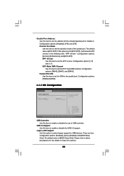
... PCI clocks for PCI device latency timer register. +F1 F9 F10 ESC Select Screen Select Item Change Option General Help Load Defaults Save and Exit Exit v02.54 (C) Copyright 1985-2003, American Megatrends, Inc. PCI Latency Timer The default value is recommended to malfunction. Configuration options: [Disabled], [Auto], [Enabled]. 32Bit Data Transfer Use this item to enable 32-bit access to maximize the IDE hard disk data transfer rate. 3.3.5 PCIPnP Configuration BIOS SETUP UTILITY Advanced Advanced PCI / PnP Settings PCI...
... PCI clocks for PCI device latency timer register. +F1 F9 F10 ESC Select Screen Select Item Change Option General Help Load Defaults Save and Exit Exit v02.54 (C) Copyright 1985-2003, American Megatrends, Inc. PCI Latency Timer The default value is recommended to malfunction. Configuration options: [Disabled], [Auto], [Enabled]. 32Bit Data Transfer Use this item to enable 32-bit access to maximize the IDE hard disk data transfer rate. 3.3.5 PCIPnP Configuration BIOS SETUP UTILITY Advanced Advanced PCI / PnP Settings PCI...
User Manual
Page 44
... USB Support Use this option to select legacy support for the onboard parallel port or disable it will show the EPP version in the following item, "EPP Version". There are four configuration options: [Enabled], [Auto], [Disabled] and [BIOS Setup Only]. Configuration options: [IRQ5] and [IRQ7]. 3.3.8 USB Configuration BIOS SETUP UTILITY Advanced USB Configuration USB Controller USB 2.0 Support Legacy USB Support [Enabled] [Enabled] [BIOS Setup Only] To enable or disable the onboard USB controllers. +F1 F9 F10 ESC Select Screen Select Item Change Option General Help Load Defaults...
... USB Support Use this option to select legacy support for the onboard parallel port or disable it will show the EPP version in the following item, "EPP Version". There are four configuration options: [Enabled], [Auto], [Disabled] and [BIOS Setup Only]. Configuration options: [IRQ5] and [IRQ7]. 3.3.8 USB Configuration BIOS SETUP UTILITY Advanced USB Configuration USB Controller USB 2.0 Support Legacy USB Support [Enabled] [Enabled] [BIOS Setup Only] To enable or disable the onboard USB controllers. +F1 F9 F10 ESC Select Screen Select Item Change Option General Help Load Defaults...
User Manual
Page 49
... 64-bit. Because motherboard settings and hardware options vary, use the setup procedures in your computer. The CD automatically displays the Main Menu if "AUTORUN" is enabled in this chapter for general reference only. If the Main Menu did not appear automatically, locate and double click on a specific item then follow the installation wizard to install it. 4.2.4 Contact Information If you may contact your CD-ROM drive. or...
... 64-bit. Because motherboard settings and hardware options vary, use the setup procedures in your computer. The CD automatically displays the Main Menu if "AUTORUN" is enabled in this chapter for general reference only. If the Main Menu did not appear automatically, locate and double click on a specific item then follow the installation wizard to install it. 4.2.4 Contact Information If you may contact your CD-ROM drive. or...
Quick Installation Guide
Page 2
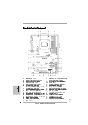
Motherboard Layout English 1 PS2_USB_PW1 Jumper 16 SATAII Connector (SATAII_2 (PORT 1.1), Red) 2 ATX 12V Power Connector (ATX12V1) 17 System Panel Header (PANEL1) 3 CPU Heatsink Retention Module 18 Chassis Speaker Header (SPEAKER 1) 4 AM2 940-Pin CPU Socket 19 NVIDIA Chipset 5 CPU Fan Connector (CPU_FAN1) 20 Chassis Fan Connector (CHA_FAN1) 6 2 x 240-pin DDR2 DIMM Slots 21 Infrared Module Header (IR1) (Dual Channel A: DDRII_1, DDRII_2; Orange) 24 Front Panel Audio Header (HD_AUDIO1) 8 Primary IDE Connector (IDE1, Blue) 25 WiFi Header (WIFI) 9 Clear CMOS Jumper (CLRCMOS1) ...
Motherboard Layout English 1 PS2_USB_PW1 Jumper 16 SATAII Connector (SATAII_2 (PORT 1.1), Red) 2 ATX 12V Power Connector (ATX12V1) 17 System Panel Header (PANEL1) 3 CPU Heatsink Retention Module 18 Chassis Speaker Header (SPEAKER 1) 4 AM2 940-Pin CPU Socket 19 NVIDIA Chipset 5 CPU Fan Connector (CPU_FAN1) 20 Chassis Fan Connector (CHA_FAN1) 6 2 x 240-pin DDR2 DIMM Slots 21 Infrared Module Header (IR1) (Dual Channel A: DDRII_1, DDRII_2; Orange) 24 Front Panel Audio Header (HD_AUDIO1) 8 Primary IDE Connector (IDE1, Blue) 25 WiFi Header (WIFI) 9 Clear CMOS Jumper (CLRCMOS1) ...
Quick Installation Guide
Page 6
... panel audio connector - 2 x USB 2.0 headers (support 3 USB 2.0 ports) (see CAUTION 6) - 1 x WiFi header (see CAUTION 11) Hardware - Supports jumperfree - Instant Boot - Hybrid Booster: - Chassis Fan Tachometer - Drivers, Utilities, AntiVirus Software (Trial Version) Unique Feature - CPU Frequency Stepless Control (see CAUTION 10) - CPU Fan Tachometer - Overclocking may affect your own risk and expense. CD in the BIOS, applying Untied Overclocking Technology, or using the thirdparty overclocking tools. Chassis Temperature Sensing - Voltage Monitoring...
... panel audio connector - 2 x USB 2.0 headers (support 3 USB 2.0 ports) (see CAUTION 6) - 1 x WiFi header (see CAUTION 11) Hardware - Supports jumperfree - Instant Boot - Hybrid Booster: - Chassis Fan Tachometer - Drivers, Utilities, AntiVirus Software (Trial Version) Unique Feature - CPU Frequency Stepless Control (see CAUTION 10) - CPU Fan Tachometer - Overclocking may affect your own risk and expense. CD in the BIOS, applying Untied Overclocking Technology, or using the thirdparty overclocking tools. Chassis Temperature Sensing - Voltage Monitoring...
Quick Installation Guide
Page 15
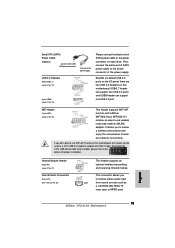
... SATA power cable to -use WiFi+AP function on this motherboard, this header can support one USB 2.0 port. This connector allows you don't plan to this motherboard. Then connect the white end of SATA power cable to support one USB 2.0 port. English 15 ASRock NF6-GLAN Motherboard To connect the 4-Pin USB device cable to this header, please refer to use wireless local area network (WLAN) adapter. If you to receive stereo audio input CD1 from sound sources such as a 4-Pin USB 2.0 header to the power connector...
... SATA power cable to -use WiFi+AP function on this motherboard, this header can support one USB 2.0 port. This connector allows you don't plan to this motherboard. Then connect the white end of SATA power cable to support one USB 2.0 port. English 15 ASRock NF6-GLAN Motherboard To connect the 4-Pin USB device cable to this header, please refer to use wireless local area network (WLAN) adapter. If you to receive stereo audio input CD1 from sound sources such as a 4-Pin USB 2.0 header to the power connector...
Quick Installation Guide
Page 16
... the panel wire on the lower right hand taskbar to [Enabled]. Connect Ground (GND) to function correctly. Enter BIOS Setup Utility. Set the Front Panel Control option from [Auto] to enter Realtek HD Audio Manager. Click the icon on the chassis must support HDA to Ground (GND). For Windows® VistaTM / VistaTM 64-bit OS: Click the right-top "Folder" icon , choose "Disable front panel jack detection", and save the change by...
... the panel wire on the lower right hand taskbar to [Enabled]. Connect Ground (GND) to function correctly. Enter BIOS Setup Utility. Set the Front Panel Control option from [Auto] to enter Realtek HD Audio Manager. Click the icon on the chassis must support HDA to Ground (GND). For Windows® VistaTM / VistaTM 64-bit OS: Click the right-top "Folder" icon , choose "Disable front panel jack detection", and save the change by...
Quick Installation Guide
Page 19
... apply Untied Overclocking Technology. 19 ASRock NF6-GLAN Motherboard English You can start to install Windows® 2000, Windows® XP, Windows® XP 64-bit, Windows® VistaTM or Windows® VistaTM 64-bit on your system directly. 2.9 Installing Windows® 2000 / XP / XP 64-bit / VistaTM / VistaTM 64-bit With RAID Functions If you enable Untied Overclocking function, please enter "Overclock Mode" option of BIOS setup to set the selection from up to bottom side to [CPU, PCIE, Async...
... apply Untied Overclocking Technology. 19 ASRock NF6-GLAN Motherboard English You can start to install Windows® 2000, Windows® XP, Windows® XP 64-bit, Windows® VistaTM or Windows® VistaTM 64-bit on your system directly. 2.9 Installing Windows® 2000 / XP / XP 64-bit / VistaTM / VistaTM 64-bit With RAID Functions If you enable Untied Overclocking function, please enter "Overclock Mode" option of BIOS setup to set the selection from up to bottom side to [CPU, PCIE, Async...
Quick Installation Guide
Page 20
... to enter BIOS Setup after POST, please restart the system by pressing + + , or pressing the reset button on the system chassis. BIOS Information The Flash Memory on the file "ASSETUP.EXE" from the "BIN" folder in the Support CD to the User Manual (PDF file) contained in your CD-ROM drive. If you wish to be user-friendly. For the detailed information about BIOS Setup, please refer to display the menus. 20 ASRock NF6-GLAN Motherboard...
... to enter BIOS Setup after POST, please restart the system by pressing + + , or pressing the reset button on the system chassis. BIOS Information The Flash Memory on the file "ASSETUP.EXE" from the "BIN" folder in the Support CD to the User Manual (PDF file) contained in your CD-ROM drive. If you wish to be user-friendly. For the detailed information about BIOS Setup, please refer to display the menus. 20 ASRock NF6-GLAN Motherboard...
RAID Installation Guide
Page 7
... disk into your SATA / SATAII HDDs with RAID functions, please follow the instruction to install Windows® VistaTM / Windows® VistaTM 64-bit OS on your system. Enter BIOS SETUP UTILITY Advanced screen IDE Configuration. If you install Windows® VistaTM / Windows® VistaTM 64-bit on IDE HDDs and want to manage (create, convert, delete, or rebuild) RAID functions on SATA / SATAII HDDs, you still need to check the RAID installation guide in the Support CD: .. \ RAID Installation Guide 7 Before you start...
... disk into your SATA / SATAII HDDs with RAID functions, please follow the instruction to install Windows® VistaTM / Windows® VistaTM 64-bit OS on your system. Enter BIOS SETUP UTILITY Advanced screen IDE Configuration. If you install Windows® VistaTM / Windows® VistaTM 64-bit on IDE HDDs and want to manage (create, convert, delete, or rebuild) RAID functions on SATA / SATAII HDDs, you still need to check the RAID installation guide in the Support CD: .. \ RAID Installation Guide 7 Before you start...
RAID Installation Guide
Page 11
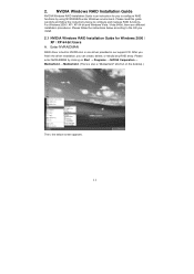
... instructions below to the OS you can create, delete, or rebuild any RAID array. Enter NVRAIDMAN RAID driver is also a "Mediashield" shortcut on the desktop.) Then, the below according to configure and manage RAID functions. NVIDIA Windows RAID Installation Guide NVIDIA Windows RAID Installation Guide is an instruction for Windows 2000 / XP / XP 64-bit Users A. 2. Please enter NVRAIDMAN by using NVIDIAMAN under Windows environment. Please read this guide carefully and follow the instructions below screen...
... instructions below to the OS you can create, delete, or rebuild any RAID array. Enter NVRAIDMAN RAID driver is also a "Mediashield" shortcut on the desktop.) Then, the below according to configure and manage RAID functions. NVIDIA Windows RAID Installation Guide NVIDIA Windows RAID Installation Guide is an instruction for Windows 2000 / XP / XP 64-bit Users A. 2. Please enter NVRAIDMAN by using NVIDIAMAN under Windows environment. Please read this guide carefully and follow the instructions below screen...


