
User Manual
Page 3
... 31 3.1 Introduction 31 3.1.1 BIOS Menu Bar 31 3.1.2 Navigation Keys 31 3.2 Main Screen 32 3.3 Advanced Screen 33 3.3.1 CPU Configuration 33 3.3.2 Chipset Configuration 38 3.3.3 ACPI Configuration 39 3.3.4 IDE Configuration 40 3 Introduction 5 1.1 Package Contents 5 1.2 Specifications 6 1.3 Motherboard Layout 10 1.4 ASRock HD 6CH I/O 11 2 . Contents 1 . Installation 12 Pre-installation Precautions 12 2.1 CPU Installation 13 2.2 Installation of CPU...
... 31 3.1 Introduction 31 3.1.1 BIOS Menu Bar 31 3.1.2 Navigation Keys 31 3.2 Main Screen 32 3.3 Advanced Screen 33 3.3.1 CPU Configuration 33 3.3.2 Chipset Configuration 38 3.3.3 ACPI Configuration 39 3.3.4 IDE Configuration 40 3 Introduction 5 1.1 Package Contents 5 1.2 Specifications 6 1.3 Motherboard Layout 10 1.4 ASRock HD 6CH I/O 11 2 . Contents 1 . Installation 12 Pre-installation Precautions 12 2.1 CPU Installation 13 2.2 Installation of CPU...
User Manual
Page 5
.... Chapter 3 and 4 contain the configuration guide to BIOS setup and information of the motherboard and step-bystep guide to quality and endurance. In this motherboard, please visit our website for specific information about the model you for purchasing ASRock NF6-GLAN motherboard, a reliable motherboard produced under ASRock's consistently stringent quality control. You may find the...
.... Chapter 3 and 4 contain the configuration guide to BIOS setup and information of the motherboard and step-bystep guide to quality and endurance. In this motherboard, please visit our website for specific information about the model you for purchasing ASRock NF6-GLAN motherboard, a reliable motherboard produced under ASRock's consistently stringent quality control. You may find the...

User Manual
Page 7
... 12V power connector - Supports jumperfree - Instant Boot - Chassis Temperature Sensing - Chassis Fan Tachometer - AMI Legal BIOS - Supports "Plug and Play" - Drivers, Utilities, AntiVirus Software (Trial Version) Unique Feature - ASRock OC Tuner (see CAUTION 7) BIOS Feature - 4Mb AMI BIOS - CPU Temperature Sensing Monitor - Overclocking may affect your system stability, or even cause damage to 12...
... 12V power connector - Supports jumperfree - Instant Boot - Chassis Temperature Sensing - Chassis Fan Tachometer - AMI Legal BIOS - Supports "Plug and Play" - Drivers, Utilities, AntiVirus Software (Trial Version) Unique Feature - ASRock OC Tuner (see CAUTION 7) BIOS Feature - 4Mb AMI BIOS - CPU Temperature Sensing Monitor - Overclocking may affect your system stability, or even cause damage to 12...
User Manual
Page 9
...If your system is unstable after AM2 Boost function is detected, the system will overclock the chipset/CPU reference clock. This motherboard supports ASRock AM2 Boost overclocking technology. 10. While CPU overheat is enabled, it back again. To improve heat dissipation, remember to spray thermal grease... between the CPU and the heatsink when you enable this function in the BIOS setup, the memory performance will improve up to 12.5%, but the effect still depends on the motherboard functions properly and unplug the ...
...If your system is unstable after AM2 Boost function is detected, the system will overclock the chipset/CPU reference clock. This motherboard supports ASRock AM2 Boost overclocking technology. 10. While CPU overheat is enabled, it back again. To improve heat dissipation, remember to spray thermal grease... between the CPU and the heatsink when you enable this function in the BIOS setup, the memory performance will improve up to 12.5%, but the effect still depends on the motherboard functions properly and unplug the ...
User Manual
Page 10
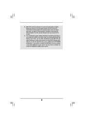
...USB4 B: USB5 30 LAN 29 PHY ATXPWR1 Top: LINE IN Center: FRONT Bottom: MIC IN PCIE1 Dual Channel PCIE2 AM2+ AM2 PCI EXPRESS NF6-GLAN IDE1 CLRCMOS1 1 28 27 26 25 PCIE3/DE Super I/O PCI1 1 HDMI_SPDIF1 AUDIO CODEC HD_AUDIO1 1 1 WIFI PCI2 PCI3 CD1 FLOPPY1 RoHS SATAII... NVIDIA GeForce 6150SE / nForce 430 or GeForce 7025 / nForce 630a Chipset 1 USB8 USB6_7 1 RAID CHA_FAN1 1 IR1 4Mb BIOS SPEAKER1 1 PANEL 1 PLED PWRBTN 1 HDLED RESET 24 23 22 21 20 19 18 17 CMOS BATTERY SATAII_2 (PORT 1.1) SATAII_4 (PORT 2.1) SATAII_1 (PORT ...
...USB4 B: USB5 30 LAN 29 PHY ATXPWR1 Top: LINE IN Center: FRONT Bottom: MIC IN PCIE1 Dual Channel PCIE2 AM2+ AM2 PCI EXPRESS NF6-GLAN IDE1 CLRCMOS1 1 28 27 26 25 PCIE3/DE Super I/O PCI1 1 HDMI_SPDIF1 AUDIO CODEC HD_AUDIO1 1 1 WIFI PCI2 PCI3 CD1 FLOPPY1 RoHS SATAII... NVIDIA GeForce 6150SE / nForce 430 or GeForce 7025 / nForce 630a Chipset 1 USB8 USB6_7 1 RAID CHA_FAN1 1 IR1 4Mb BIOS SPEAKER1 1 PANEL 1 PLED PWRBTN 1 HDLED RESET 24 23 22 21 20 19 18 17 CMOS BATTERY SATAII_2 (PORT 1.1) SATAII_4 (PORT 2.1) SATAII_1 (PORT ...

User Manual
Page 17
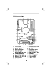
... jumper whose pin1 and pin2 are setup. Note: To select +5VSB, it down before you do not clear the CMOS right after you update the BIOS. If you must boot up events. Jumper Setting PS2_USB_PW1 1_2 2_3 Short pin2, pin3 to enable (see p.10, No. 9) 1_2 2_3 Default Clear CMOS... Note: CLRCMOS1 allows you to clear the CMOS when you just finish updating the BIOS, you need to clear the data in CMOS includes system setup information such as system password, date, time, and system setup parameters. 2.5 Jumpers Setup The...
... jumper whose pin1 and pin2 are setup. Note: To select +5VSB, it down before you do not clear the CMOS right after you update the BIOS. If you must boot up events. Jumper Setting PS2_USB_PW1 1_2 2_3 Short pin2, pin3 to enable (see p.10, No. 9) 1_2 2_3 Default Clear CMOS... Note: CLRCMOS1 allows you to clear the CMOS when you just finish updating the BIOS, you need to clear the data in CMOS includes system setup information such as system password, date, time, and system setup parameters. 2.5 Jumpers Setup The...
User Manual
Page 20
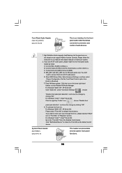
... detection", and save the change by clicking "OK". If you use AC'97 audio panel, please install it to function correctly. Enter Windows system. Enter BIOS Setup Utility. To activate the front mic. Please follow the instruction in "Front Mic" of audio devices. 1. B. You don't need to make the Front Mic...
... detection", and save the change by clicking "OK". If you use AC'97 audio panel, please install it to function correctly. Enter Windows system. Enter BIOS Setup Utility. To activate the front mic. Please follow the instruction in "Front Mic" of audio devices. 1. B. You don't need to make the Front Mic...

User Manual
Page 28
Please follow below steps. Before installing Windows® 2000 to your system, your Windows® 2000 optical disk is supposed to change the BIOS setting. STEP 1: Make a SATA / SATAII Driver Diskette. Then, the drivers compatible to your system can be auto-detected and listed on your ... please follow the order from up , press key, and then a window for you just want to install those required drivers. A. Insert the ASRock Support CD into your optical drive to your optical drive first. During POST at the beginning of making a SP4 disk: http://www.microsoft.com/Windows2000...
Please follow below steps. Before installing Windows® 2000 to your system, your Windows® 2000 optical disk is supposed to change the BIOS setting. STEP 1: Make a SATA / SATAII Driver Diskette. Then, the drivers compatible to your system can be auto-detected and listed on your ... please follow the order from up , press key, and then a window for you just want to install those required drivers. A. Insert the ASRock Support CD into your optical drive to your optical drive first. During POST at the beginning of making a SP4 disk: http://www.microsoft.com/Windows2000...
User Manual
Page 29
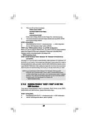
... the RAID configuration by using the Windows RAID installation guide in the following path in BIOS first. The system will start Please insert a floppy diskette into the floppy diskette. Enter BIOS SETUP UTILITY Advanced screen IDE Configuration. After step1, 2, 3, you still need to...: .. \ RAID Installation Guide 2.14.2 Installing Windows® VistaTM / VistaTM 64-bit With RAID Functions If you will be presented. A. Enter BIOS SETUP UTILITY Advanced screen B. E. A. Set the "SATA Operation Mode" option to [RAID]. When prompted, insert the SATA / SATAII driver diskette ...
... the RAID configuration by using the Windows RAID installation guide in the following path in BIOS first. The system will start Please insert a floppy diskette into the floppy diskette. Enter BIOS SETUP UTILITY Advanced screen IDE Configuration. After step1, 2, 3, you still need to...: .. \ RAID Installation Guide 2.14.2 Installing Windows® VistaTM / VistaTM 64-bit With RAID Functions If you will be presented. A. Enter BIOS SETUP UTILITY Advanced screen B. E. A. Set the "SATA Operation Mode" option to [RAID]. When prompted, insert the SATA / SATAII driver diskette ...
User Manual
Page 30
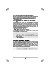
...Overclocking Technology This motherboard supports Untied Overclocking Technology, which means during overclocking, but PCI / PCIE buses are in the following path in BIOS first. Before you apply Untied Overclocking Technology. 30 Please refer to load the NVIDIA® RAID drivers. Before you start to configure...174; VistaTM / Windows® VistaTM 64-bit OS on IDE HDDs and want to continue the installation. " page, please insert the ASRock Support CD into the optical drive again to install Windows? Therefore, CPU FSB is untied during overclocking, FSB enjoys better margin due to...
...Overclocking Technology This motherboard supports Untied Overclocking Technology, which means during overclocking, but PCI / PCIE buses are in the following path in BIOS first. Before you apply Untied Overclocking Technology. 30 Please refer to load the NVIDIA® RAID drivers. Before you start to configure...174; VistaTM / Windows® VistaTM 64-bit OS on IDE HDDs and want to continue the installation. " page, please insert the ASRock Support CD into the optical drive again to install Windows? Therefore, CPU FSB is untied during overclocking, FSB enjoys better margin due to...

User Manual
Page 31
...UTILITY, otherwise, POST will continue with the following selections: Main To set up the system time/date information Advanced To set up the advanced BIOS features H/W Monitor To display current hardware status Boot To set up the default system device to locate and load the Operating System Security To ...set up the computer. The Flash Memory on . Please press during the Power-On-Self-Test (POST) to enter the BIOS SETUP UTILITY after POST, restart the system by pressing + + , or by turning the system off and then back on the motherboard stores the...
...UTILITY, otherwise, POST will continue with the following selections: Main To set up the system time/date information Advanced To set up the advanced BIOS features H/W Monitor To display current hardware status Boot To set up the default system device to locate and load the Operating System Security To ...set up the computer. The Flash Memory on . Please press during the Power-On-Self-Test (POST) to enter the BIOS SETUP UTILITY after POST, restart the system by pressing + + , or by turning the system off and then back on the motherboard stores the...
User Manual
Page 32
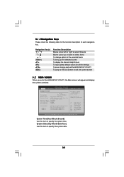
...To load optimal default values for the function description of each navigation key. Main Advanced BIOS SETUP UTILITY H/W Monitor Boot System Overview System Time System Date [17:00:09] [Wed 07/09/2008] BIOS Version : NF6-GLAN BIOS P1.00 Processor Type : AMD Athlon(tm) 64 X2 Dual Core Processor 5000+ (...TAB] to specify the system time. 3.1.2 Navigation Keys Please check the following table for all the settings To save changes and exit the BIOS SETUP UTILITY To jump to configure system Time. +Tab F1 F9 F10 ESC Select Screen Select Item Change Field Select Field General Help ...
...To load optimal default values for the function description of each navigation key. Main Advanced BIOS SETUP UTILITY H/W Monitor Boot System Overview System Time System Date [17:00:09] [Wed 07/09/2008] BIOS Version : NF6-GLAN BIOS P1.00 Processor Type : AMD Athlon(tm) 64 X2 Dual Core Processor 5000+ (...TAB] to specify the system time. 3.1.2 Navigation Keys Please check the following table for all the settings To save changes and exit the BIOS SETUP UTILITY To jump to configure system Time. +Tab F1 F9 F10 ESC Select Screen Select Item Change Field Select Field General Help ...

User Manual
Page 33
...Configuration, PCIPnP Configuration, Floppy Configuration, SuperIO Configuration, and USB Configuration. Setting wrong values in this option to [Enabled], you will enable ASRock AM2 Boost function, which will be left at the rated frequency/voltage. 3.3 Advanced Screen In this section, you may set the configurations...F1 General Help F9 Load Defaults F10 Save and Exit ESC Exit v02.54 (C) Copyright 1985-2003, American Megatrends, Inc. Main BIOS SETUP UTILITY Advanced H/W Monitor Boot Security Exit Advanced Settings WARNING : Setting wrong values in Setup. +F1 F9 F10 ESC Select ...
...Configuration, PCIPnP Configuration, Floppy Configuration, SuperIO Configuration, and USB Configuration. Setting wrong values in this option to [Enabled], you will enable ASRock AM2 Boost function, which will be left at the rated frequency/voltage. 3.3 Advanced Screen In this section, you may set the configurations...F1 General Help F9 Load Defaults F10 Save and Exit ESC Exit v02.54 (C) Copyright 1985-2003, American Megatrends, Inc. Main BIOS SETUP UTILITY Advanced H/W Monitor Boot Security Exit Advanced Settings WARNING : Setting wrong values in Setup. +F1 F9 F10 ESC Select ...

User Manual
Page 35
.... Processor Target Frequency This option appears only when you adopt Phenom CPU. North Bridge Target Frequency This option appears only when you adopt Phenom CPU. BIOS SETUP UTILITY Advanced CPU Configuration AM2 Boost Overclock Mode CPU Frequency (MHz) PCIE Frequency (MHz) CPU/LDT Spread Spectrum PCIE Spread Spectrum SATA Spread Spectrum...
.... Processor Target Frequency This option appears only when you adopt Phenom CPU. North Bridge Target Frequency This option appears only when you adopt Phenom CPU. BIOS SETUP UTILITY Advanced CPU Configuration AM2 Boost Overclock Mode CPU Frequency (MHz) PCIE Frequency (MHz) CPU/LDT Spread Spectrum PCIE Spread Spectrum SATA Spread Spectrum...
User Manual
Page 38
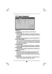
... the type of Primary VGA in case of this feature is [Auto]. The default value is [PCI]. The default value is plugged. CPU - 3.3.2 Chipset Configuration BIOS SETUP UTILITY Advanced Chipset Settings Onboard LAN Onboard HD Audio Front Panel Primary Graphics Adapter [Enabled] [Auto] [Auto] [PCI] CPU-NB Link Speed CPU-NB...
... the type of Primary VGA in case of this feature is [Auto]. The default value is [PCI]. The default value is plugged. CPU - 3.3.2 Chipset Configuration BIOS SETUP UTILITY Advanced Chipset Settings Onboard LAN Onboard HD Audio Front Panel Primary Graphics Adapter [Enabled] [Auto] [Auto] [PCI] CPU-NB Link Speed CPU-NB...

User Manual
Page 39
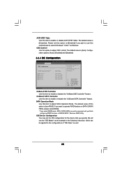
3.3.3 ACPI Configuration BIOS SETUP UTILITY Advanced ACPI Settings Suspend To RAM Repost Video on STR Resume Away Mode Support Restore on the system from the power-soft-off ...
3.3.3 ACPI Configuration BIOS SETUP UTILITY Advanced ACPI Settings Suspend To RAM Repost Video on STR Resume Away Mode Support Restore on the system from the power-soft-off ...
User Manual
Page 40
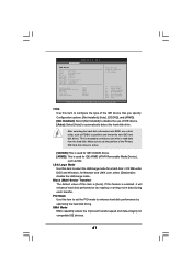
...of this option to enable or disable the "OnBoard SATA Controller" feature. Configuration options: [Auto], [Enabled] and [Disabled]. 3.3.4 IDE Configuration BIOS SETUP UTILITY Advanced IDE Configuration OnBoard IDE Controller OnBoard SATA Controller SATA Operation Mode IDE Master IDE Slave SATAII 1 SATAII 2 SATAII 3 SATAII 4...be accessed until you plan to adjust SATA Operation Mode. The default value of "IDE Slave" as the example in NVIDIA BIOS / Windows RAID Utility. OnBoard IDE Controller Use this item to adjust OSC control. The default value is [Disabled]. OnBoard ...
...of this option to enable or disable the "OnBoard SATA Controller" feature. Configuration options: [Auto], [Enabled] and [Disabled]. 3.3.4 IDE Configuration BIOS SETUP UTILITY Advanced IDE Configuration OnBoard IDE Controller OnBoard SATA Controller SATA Operation Mode IDE Master IDE Slave SATAII 1 SATAII 2 SATAII 3 SATAII 4...be accessed until you plan to adjust SATA Operation Mode. The default value of "IDE Slave" as the example in NVIDIA BIOS / Windows RAID Utility. OnBoard IDE Controller Use this item to adjust OSC control. The default value is [Disabled]. OnBoard ...
User Manual
Page 41
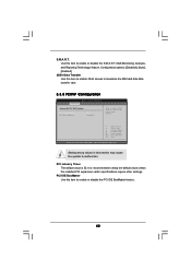
BIOS SETUP UTILITY Advanced IDE Master Device Vendor Size LBA Mode Block Mode PIO Mode Async DMA Ultra DMA S.M.A.R.T. :Hard Disk :MAXTOR 6L080J4 :80.0 GB :Supported :... S.M.A.R.T. 32Bit Data Transfer [Auto] [Auto] [Auto] [Auto] [Auto] [Disabled] [Disabled] Select the type of this item is [Auto]. After selecting the hard disk information into BIOS, use of the Primary IDE hard disk drives to the system. +F1 F9 F10 ESC Select Screen Select Item Change Option General Help Load Defaults...
BIOS SETUP UTILITY Advanced IDE Master Device Vendor Size LBA Mode Block Mode PIO Mode Async DMA Ultra DMA S.M.A.R.T. :Hard Disk :MAXTOR 6L080J4 :80.0 GB :Supported :... S.M.A.R.T. 32Bit Data Transfer [Auto] [Auto] [Auto] [Auto] [Auto] [Disabled] [Disabled] Select the type of this item is [Auto]. After selecting the hard disk information into BIOS, use of the Primary IDE hard disk drives to the system. +F1 F9 F10 ESC Select Screen Select Item Change Option General Help Load Defaults...
User Manual
Page 42
... expansion cards' specifications require other settings. PCI Latency Timer The default value is recommended to maximize the IDE hard disk data transfer rate. 3.3.5 PCIPnP Configuration BIOS SETUP UTILITY Advanced Advanced PCI / PnP Settings PCI Latency Timer PCI IDE BusMaster [32] [Enabled] Value in this item to enable or disable the S.M.A.R.T. (Self...
... expansion cards' specifications require other settings. PCI Latency Timer The default value is recommended to maximize the IDE hard disk data transfer rate. 3.3.5 PCIPnP Configuration BIOS SETUP UTILITY Advanced Advanced PCI / PnP Settings PCI Latency Timer PCI IDE BusMaster [32] [Enabled] Value in this item to enable or disable the S.M.A.R.T. (Self...
User Manual
Page 43
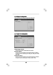
... General Help Load Defaults Save and Exit Exit v02.54 (C) Copyright 1985-2003, American Megatrends, Inc. 3.3.7 Super IO Configuration BIOS SETUP UTILITY Advanced Configure Super IO Chipset OnBoard Floppy Controller Serial Port Address Infrared Port Address Parallel Port Address Parallel Port Mode EPP... ECP Mode DMA Channel Parallel Port IRQ [Enabled] [3F8 / IRQ4] [Disabled] [378] [ECP + EPP] [1.9] [DMA3] [IRQ7] Allow BIOS to enable or disable floppy drive controller. BIOS SETUP UTILITY Advanced Floppy Configuration Floppy A [1.44 MB 312"] Select the type of your floppy drive.
... General Help Load Defaults Save and Exit Exit v02.54 (C) Copyright 1985-2003, American Megatrends, Inc. 3.3.7 Super IO Configuration BIOS SETUP UTILITY Advanced Configure Super IO Chipset OnBoard Floppy Controller Serial Port Address Infrared Port Address Parallel Port Address Parallel Port Mode EPP... ECP Mode DMA Channel Parallel Port IRQ [Enabled] [3F8 / IRQ4] [Disabled] [378] [ECP + EPP] [1.9] [DMA3] [IRQ7] Allow BIOS to enable or disable floppy drive controller. BIOS SETUP UTILITY Advanced Floppy Configuration Floppy A [1.44 MB 312"] Select the type of your floppy drive.


