
User Manual
Page 5
... motherboard, please visit our website for purchasing ASRock N73PV-GS / N73PV-S motherboard, a reliable motherboard produced under ASRock's consistently stringent quality control. You may find the latest VGA cards and CPU support lists on ASRock website without notice. Chapter 3 and 4 ... will be available on ASRock website as well. www.asrock.com/support/index.asp 1.1 Package Contents ASRock N73PV-GS / N73PV-S Motherboard (Micro ATX Form Factor: 9.6-in x 7.0-in, 24.4 cm x 17.8 cm) ASRock N73PV-GS / N73PV-S Quick Installation Guide ASRock N73PV-GS / N73PV-S Support CD One 80...
... motherboard, please visit our website for purchasing ASRock N73PV-GS / N73PV-S motherboard, a reliable motherboard produced under ASRock's consistently stringent quality control. You may find the latest VGA cards and CPU support lists on ASRock website without notice. Chapter 3 and 4 ... will be available on ASRock website as well. www.asrock.com/support/index.asp 1.1 Package Contents ASRock N73PV-GS / N73PV-S Motherboard (Micro ATX Form Factor: 9.6-in x 7.0-in, 24.4 cm x 17.8 cm) ASRock N73PV-GS / N73PV-S Quick Installation Guide ASRock N73PV-GS / N73PV-S Support CD One 80...

Quick Installation Guide
Page 1
... Perchlorate, a toxic substance controlled in Perchlorate Best Management Practices (BMP) regulations passed by the California Legislature. ASRock assumes no event shall ASRock, its directors, officers, employees, or agents be registered trademarks or copyrights of their respective companies, and are...informational use only and subject to change without notice, and should not be constructed as a commitment by ASRock. All rights reserved. 1 ASRock N73PV-GS / N73PV-S Motherboard English Copyright Notice: No part of this installation guide may be reproduced, transcribed, transmitted, or ...
... Perchlorate, a toxic substance controlled in Perchlorate Best Management Practices (BMP) regulations passed by the California Legislature. ASRock assumes no event shall ASRock, its directors, officers, employees, or agents be registered trademarks or copyrights of their respective companies, and are...informational use only and subject to change without notice, and should not be constructed as a commitment by ASRock. All rights reserved. 1 ASRock N73PV-GS / N73PV-S Motherboard English Copyright Notice: No part of this installation guide may be reproduced, transcribed, transmitted, or ...

Quick Installation Guide
Page 2
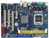
... BIOS SPI Chip 11 Third SATAII Connector (SATAII_3; Red) 26 USB 2.0 Header (USB4_5, Blue) 14 System Panel Header (PANEL1, Orange) 27 ATX 12V Connector (ATX12V1) 2 ASRock N73PV-GS / N73PV-S Motherboard Red) 25 USB 2.0 Header (USB6_7, Blue) 13 Secondary SATAII Connector (SATAII_2; Yellow) (HD_AUDIO1, Lime) 6 ATX Power Connector (ATXPWR1) 19 Internal Audio Connector: CD1...
... BIOS SPI Chip 11 Third SATAII Connector (SATAII_3; Red) 26 USB 2.0 Header (USB4_5, Blue) 14 System Panel Header (PANEL1, Orange) 27 ATX 12V Connector (ATX12V1) 2 ASRock N73PV-GS / N73PV-S Motherboard Red) 25 USB 2.0 Header (USB6_7, Blue) 13 Secondary SATAII Connector (SATAII_2; Yellow) (HD_AUDIO1, Lime) 6 ATX Power Connector (ATXPWR1) 19 Internal Audio Connector: CD1...

Quick Installation Guide
Page 3
... Speaker, or select "Realtek HDA Audio 2nd output" to "Quadraphonic" or "Stereo". Please refer to the front panel audio header. Then reboot your system. 3 ASRock N73PV-GS / N73PV-S Motherboard English For Windows® XP: After restarting your system. Click "Device advanced settings", choose "Make front and rear output devices playbacks two different audio...
... Speaker, or select "Realtek HDA Audio 2nd output" to "Quadraphonic" or "Stereo". Please refer to the front panel audio header. Then reboot your system. 3 ASRock N73PV-GS / N73PV-S Motherboard English For Windows® XP: After restarting your system. Click "Device advanced settings", choose "Make front and rear output devices playbacks two different audio...

Quick Installation Guide
Page 4
... support related to this manual will be found in the user manual presented in , 24.4 cm x 17.8 cm) ASRock N73PV-GS / N73PV-S Quick Installation Guide ASRock N73PV-GS / N73PV-S Support CD One 80-conductor Ultra ATA 66/100/133 IDE Ribbon Cable (Optional) One Serial ATA (SATA) Data ...subject to quality and endurance. You may find the latest VGA cards and CPU support lists on ASRock website without notice. www.asrock.com/support/index.asp 1.1 Package Contents ASRock N73PV-GS / N73PV-S Motherboard (Micro ATX Form Factor: 9.6-in x 7.0-in the Support CD. This Quick Installation Guide...
... support related to this manual will be found in the user manual presented in , 24.4 cm x 17.8 cm) ASRock N73PV-GS / N73PV-S Quick Installation Guide ASRock N73PV-GS / N73PV-S Support CD One 80-conductor Ultra ATA 66/100/133 IDE Ribbon Cable (Optional) One Serial ATA (SATA) Data ...subject to quality and endurance. You may find the latest VGA cards and CPU support lists on ASRock website without notice. www.asrock.com/support/index.asp 1.1 Package Contents ASRock N73PV-GS / N73PV-S Motherboard (Micro ATX Form Factor: 9.6-in x 7.0-in the Support CD. This Quick Installation Guide...

Quick Installation Guide
Page 5
... Quad Core Yorkfield and Dual Core Wolfdale processors - Integrated NVIDIA® GeForce 7100 - Supports Wake-On-LAN I /O Connector - Max. Max. N73PV-GS: Realtek Giga PHY RTL8211CL, speed 10/100/1000 Mb/s - N73PV-S: Realtek PHY RTL8201EL, speed 10/100 Ethernet - HD Audio Jack: Line in , 24.4 cm x 17.8 cm - capacity of system memory.../s connectors, support RAID (RAID 0, RAID 1, RAID 0+1, JBOD and RAID 5), NCQ, AHCI and "Hot Plug" functions (see CAUTION 5) - 1 x ATA133 IDE connector (supports 2 x IDE devices) - 1 x Floppy connector 5 ASRock N73PV-GS / N73PV-S Motherboard English
... Quad Core Yorkfield and Dual Core Wolfdale processors - Integrated NVIDIA® GeForce 7100 - Supports Wake-On-LAN I /O Connector - Max. Max. N73PV-GS: Realtek Giga PHY RTL8211CL, speed 10/100/1000 Mb/s - N73PV-S: Realtek PHY RTL8201EL, speed 10/100 Ethernet - HD Audio Jack: Line in , 24.4 cm x 17.8 cm - capacity of system memory.../s connectors, support RAID (RAID 0, RAID 1, RAID 0+1, JBOD and RAID 5), NCQ, AHCI and "Hot Plug" functions (see CAUTION 5) - 1 x ATA133 IDE connector (supports 2 x IDE devices) - 1 x Floppy connector 5 ASRock N73PV-GS / N73PV-S Motherboard English

Quick Installation Guide
Page 6
..., or even cause damage to the components and devices of your own risk and expense. English 6 ASRock N73PV-GS / N73PV-S Motherboard Supports "Plug and Play" - Instant Boot - CPU Fan Tachometer - It should be done at your system. ASRock OC Tuner (see CAUTION 9) - AMI Legal BIOS - Drivers, Utilities, AntiVirus Software (Trial Version) Unique Feature - FCC...
..., or even cause damage to the components and devices of your own risk and expense. English 6 ASRock N73PV-GS / N73PV-S Motherboard Supports "Plug and Play" - Instant Boot - CPU Fan Tachometer - It should be done at your system. ASRock OC Tuner (see CAUTION 9) - AMI Legal BIOS - Drivers, Utilities, AntiVirus Software (Trial Version) Unique Feature - FCC...

Quick Installation Guide
Page 7
...also connect SATA hard disk to spray thermal grease between the CPU and the heatsink when you install the PC system. 7 ASRock N73PV-GS / N73PV-S Motherboard English Although this motherboard offers stepless control, it is no such limitation. 4. Due to SATAII connector, please read... Please check NVIDIA® website for USB 2.0 works fine under Windows® environment. Frequencies other words, it back again. ASRock website: http://www.asrock.com 8. Please visit our website for details. 3. To improve heat dissipation, remember to SATAII connector directly. 6. Please read...
...also connect SATA hard disk to spray thermal grease between the CPU and the heatsink when you install the PC system. 7 ASRock N73PV-GS / N73PV-S Motherboard English Although this motherboard offers stepless control, it is no such limitation. 4. Due to SATAII connector, please read... Please check NVIDIA® website for USB 2.0 works fine under Windows® environment. Frequencies other words, it back again. ASRock website: http://www.asrock.com 8. Please visit our website for details. 3. To improve heat dissipation, remember to SATAII connector directly. 6. Please read...

Quick Installation Guide
Page 8
... use a grounded wrist strap or touch a safety grounded object before you install motherboard components or change any component. Otherwise, the CPU will be seriously damaged. 8 ASRock N73PV-GS / N73PV-S Motherboard English
... use a grounded wrist strap or touch a safety grounded object before you install motherboard components or change any component. Otherwise, the CPU will be seriously damaged. 8 ASRock N73PV-GS / N73PV-S Motherboard English

Quick Installation Guide
Page 9
Disengaging the lever by depressing down and out on center of PnP cap to assist in removal. 9 ASRock N73PV-GS / N73PV-S Motherboard English Step 1-2. Insert the 775-LAND CPU: Step 2-1. Orient the CPU with the two alignment keys of the CPU with IHS (Integrated Heat Sink) ...
Disengaging the lever by depressing down and out on center of PnP cap to assist in removal. 9 ASRock N73PV-GS / N73PV-S Motherboard English Step 1-2. Insert the 775-LAND CPU: Step 2-1. Orient the CPU with the two alignment keys of the CPU with IHS (Integrated Heat Sink) ...

Quick Installation Guide
Page 10
... installation of the heatsink for after service. Rotate the load plate onto the IHS. Secure load lever with fan operation or contact other components. 10 ASRock N73PV-GS / N73PV-S Motherboard English Connect fan header with the motherboard throughholes. Step 4. While pressing down the fasteners without rotating them clockwise, the heatsink cannot be placed...
... installation of the heatsink for after service. Rotate the load plate onto the IHS. Secure load lever with fan operation or contact other components. 10 ASRock N73PV-GS / N73PV-S Motherboard English Connect fan header with the motherboard throughholes. Step 4. While pressing down the fasteners without rotating them clockwise, the heatsink cannot be placed...

Quick Installation Guide
Page 11
... the notch on the DIMM matches the break on the slot. English The DIMM only fits in place and the DIMM is properly seated. 11 ASRock N73PV-GS / N73PV-S Motherboard Step 1. 2.3 Installation of Memory Modules (DIMM) This motherboard provides two 240-pin DDR2 (Double Data Rate 2) DIMM slots. It will cause permanent damage...
... the notch on the DIMM matches the break on the slot. English The DIMM only fits in place and the DIMM is properly seated. 11 ASRock N73PV-GS / N73PV-S Motherboard Step 1. 2.3 Installation of Memory Modules (DIMM) This motherboard provides two 240-pin DDR2 (Double Data Rate 2) DIMM slots. It will cause permanent damage...

Quick Installation Guide
Page 12
PCIE2 (PCIE x16 slot) is unplugged. Keep the screws for PCI Express cards with screws. 12 ASRock N73PV-GS / N73PV-S Motherboard English Align the card connector with x16 lane width graphics cards. Step 4. Remove the bracket facing the slot that the power supply is switched ...
PCIE2 (PCIE x16 slot) is unplugged. Keep the screws for PCI Express cards with screws. 12 ASRock N73PV-GS / N73PV-S Motherboard English Align the card connector with x16 lane width graphics cards. Step 4. Remove the bracket facing the slot that the power supply is switched ...

Quick Installation Guide
Page 13
... default value of the multi-monitor according to be designated as appropriate for the diaplay icon identified by the number 2. Click the number "2" icon. 13 ASRock N73PV-GS / N73PV-S Motherboard English If you select is no need to display a large number on PCI Express VGA card. 3. Click the "Identify" button to install it...
... default value of the multi-monitor according to be designated as appropriate for the diaplay icon identified by the number 2. Click the number "2" icon. 13 ASRock N73PV-GS / N73PV-S Motherboard English If you select is no need to display a large number on PCI Express VGA card. 3. Click the "Identify" button to install it...

Quick Installation Guide
Page 14
... "Extend the desktop onto this monitor". Clear CMOS Jumper (CLRCMOS1) (see p.2 No. 1) +5VSB (standby) for the display icon identified by power supply. English 14 ASRock N73PV-GS / N73PV-S Motherboard Click "OK" to short pin2 and pin3 on these 2 pins. If you to use a jumper cap to save your monitors that you would like...
... "Extend the desktop onto this monitor". Clear CMOS Jumper (CLRCMOS1) (see p.2 No. 1) +5VSB (standby) for the display icon identified by power supply. English 14 ASRock N73PV-GS / N73PV-S Motherboard Click "OK" to short pin2 and pin3 on these 2 pins. If you to use a jumper cap to save your monitors that you would like...

Quick Installation Guide
Page 15
... SATA data cables for the details. Do NOT place jumper caps over the headers and connectors will cause permanent damage of the power supply. 15 ASRock N73PV-GS / N73PV-S Motherboard English
... SATA data cables for the details. Do NOT place jumper caps over the headers and connectors will cause permanent damage of the power supply. 15 ASRock N73PV-GS / N73PV-S Motherboard English

Quick Installation Guide
Page 16
... I/O panel, there are three USB 2.0 headers on the chassis must support HDA to receive stereo audio input from sound sources such as below: 16 ASRock N73PV-GS / N73PV-S Motherboard English If you CD1 to function correctly. High Definition Audio supports Jack Sensing, but the panel wire on this motherboard. This connector allows you...
... I/O panel, there are three USB 2.0 headers on the chassis must support HDA to receive stereo audio input from sound sources such as below: 16 ASRock N73PV-GS / N73PV-S Motherboard English If you CD1 to function correctly. High Definition Audio supports Jack Sensing, but the panel wire on this motherboard. This connector allows you...

Quick Installation Guide
Page 17
... enter Realtek HD Audio Manager. Click the icon on this connector and match the black wire to this header. Pin 1-3 Connected 3-Pin Fan Installation 17 ASRock N73PV-GS / N73PV-S Motherboard Enter BIOS Setup Utility. Connect Audio_R (RIN) to OUT2_R and Audio_L (LIN) to MIC2_L. F. Please connect a chassis fan cable to this motherboard, please...
... enter Realtek HD Audio Manager. Click the icon on this connector and match the black wire to this header. Pin 1-3 Connected 3-Pin Fan Installation 17 ASRock N73PV-GS / N73PV-S Motherboard Enter BIOS Setup Utility. Connect Audio_R (RIN) to OUT2_R and Audio_L (LIN) to MIC2_L. F. Please connect a chassis fan cable to this motherboard, please...

Quick Installation Guide
Page 18
... a traditional 20-pin ATX power supply. Then, the drivers compatible to install Windows® XP / Windows® XP 64-bit on your system. 18 ASRock N73PV-GS / N73PV-S Motherboard English Please follow below procedures according to the OS you install. 2.9.1 Installing Windows® XP / XP 64-bit Without RAID Functions If you want...
... a traditional 20-pin ATX power supply. Then, the drivers compatible to install Windows® XP / Windows® XP 64-bit on your system. 18 ASRock N73PV-GS / N73PV-S Motherboard English Please follow below procedures according to the OS you install. 2.9.1 Installing Windows® XP / XP 64-bit Without RAID Functions If you want...

Quick Installation Guide
Page 19
...drivers are in the following path in the motherboard gift box pack, please choose the one for detailed procedures: ..\ RAID Installation Guide 19 ASRock N73PV-GS / N73PV-S Motherboard English 12 24 on 1 13 2.9.2 Installing Windows® VistaTM / VistaTM 64-bit Without RAID Functions If you want to ...and follow below steps. B. A. Using SATA / SATAII HDDs with RAID functions, please refer to [AHCI]. " page, please insert the ASRock Support CD into the optical drive to boot your SATA / SATAII HDDs without NCQ and Hot Plug functions STEP 1: Set Up BIOS. When...
...drivers are in the following path in the motherboard gift box pack, please choose the one for detailed procedures: ..\ RAID Installation Guide 19 ASRock N73PV-GS / N73PV-S Motherboard English 12 24 on 1 13 2.9.2 Installing Windows® VistaTM / VistaTM 64-bit Without RAID Functions If you want to ...and follow below steps. B. A. Using SATA / SATAII HDDs with RAID functions, please refer to [AHCI]. " page, please insert the ASRock Support CD into the optical drive to boot your SATA / SATAII HDDs without NCQ and Hot Plug functions STEP 1: Set Up BIOS. When...


