

User Manual
Page 4
... 1 1.2 Speciications 2 1.3 Motherboard Layout 5 1.4 I/O Panel 7 Chapter 2 Installation 9 2.1 Installing Memory Modules (SO-DIMM) 10 2.2 Expansion Slots (PCI Express Slots) 12 2.3 Jumpers Setup 13 2.4 Onboard Headers and Connectors 14 Chapter 3 Software and Utilities Operation 18 3.1 Installing Drivers 18 3.2 ASRock APP Shop 19 3.2.1 UI Overview 19 3.2.2 Apps 20 3.2.3 BIOS & Drivers 23 3.2.4 Setting 24 3.3 Creating Windows® 7 Installation Disk with USB 3.0 Drivers Packed 25 Chapter 4 UEFI SETUP UTILITY 29 4.1 Introduction 29 4.1.1 UEFI Menu Bar 29
... 1 1.2 Speciications 2 1.3 Motherboard Layout 5 1.4 I/O Panel 7 Chapter 2 Installation 9 2.1 Installing Memory Modules (SO-DIMM) 10 2.2 Expansion Slots (PCI Express Slots) 12 2.3 Jumpers Setup 13 2.4 Onboard Headers and Connectors 14 Chapter 3 Software and Utilities Operation 18 3.1 Installing Drivers 18 3.2 ASRock APP Shop 19 3.2.1 UI Overview 19 3.2.2 Apps 20 3.2.3 BIOS & Drivers 23 3.2.4 Setting 24 3.3 Creating Windows® 7 Installation Disk with USB 3.0 Drivers Packed 25 Chapter 4 UEFI SETUP UTILITY 29 4.1 Introduction 29 4.1.1 UEFI Menu Bar 29

User Manual
Page 6
... ind the latest VGA cards and CPU support list on ASRock's website without notice. ASRock website http://www.asrock.com. 1.1 Package Contents • ASRock N3700-ITX / N3150-ITX Motherboard (Mini-ITX Form Factor) • ASRock N3700-ITX / N3150-ITX Quick Installation Guide • ASRock N3700-ITX / N3150-ITX Support CD • 2 x Serial ATA (SATA) Data Cables (Optional) • 1 x I/O Panel Shield • 1 x WiFi Module Screw 1 English It delivers excellent performance with robust design conforming to ASRock's commitment to change without further notice. Chapter...
... ind the latest VGA cards and CPU support list on ASRock's website without notice. ASRock website http://www.asrock.com. 1.1 Package Contents • ASRock N3700-ITX / N3150-ITX Motherboard (Mini-ITX Form Factor) • ASRock N3700-ITX / N3150-ITX Quick Installation Guide • ASRock N3700-ITX / N3150-ITX Support CD • 2 x Serial ATA (SATA) Data Cables (Optional) • 1 x I/O Panel Shield • 1 x WiFi Module Screw 1 English It delivers excellent performance with robust design conforming to ASRock's commitment to change without further notice. Chapter...
User Manual
Page 7
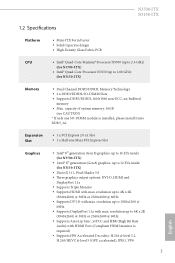
... Slot • 1 x Half-size Mini-PCI Express Slot Graphics • Intel® 8th generation (Gen 8) graphics: up to 16 EUs inside (for N3150-ITX) Memory • Dual Channel DDR3/DDR3L Memory Technology • 2 x DDR3/DDR3L SO-DIMM Slots • Supports DDR3/DDR3L 1600/1066 non-ECC, un-bufered memory • Max. N3700-ITX N3150-ITX 1.2 Speciications Platform • Mini-ITX Form Factor • Solid Capacitor design • High Density Glass Fabric PCB CPU...
... Slot • 1 x Half-size Mini-PCI Express Slot Graphics • Intel® 8th generation (Gen 8) graphics: up to 16 EUs inside (for N3150-ITX) Memory • Dual Channel DDR3/DDR3L Memory Technology • 2 x DDR3/DDR3L SO-DIMM Slots • Supports DDR3/DDR3L 1600/1066 non-ECC, un-bufered memory • Max. N3700-ITX N3150-ITX 1.2 Speciications Platform • Mini-ITX Form Factor • Solid Capacitor design • High Density Glass Fabric PCB CPU...
User Manual
Page 9
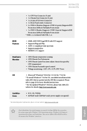
N3700-ITX N3150-ITX BIOS Feature Hardware Monitor OS Certiications • 1 x CPU Fan Connector (3-pin) • 1 x Chassis Fan Connector (3-pin) • 1 x 24 pin ATX Power Connector • 1 x Front Panel Audio Connector • 2 x USB 2.0 Headers (Support 4 USB 2.0 ports) (Supports ESD Protection (ASRock Full Spike Protection)) • 1 x USB 3.0 Header (Supports 2 USB 3.0 ports) (Supports ESD Protection (ASRock Full Spike Protection)) * USB3_3_4 is shared with USB_5_6. • 64Mb AMI UEFI Legal BIOS with GUI support • Supports Plug and Play • ACPI 1.1 compliant wake up...
N3700-ITX N3150-ITX BIOS Feature Hardware Monitor OS Certiications • 1 x CPU Fan Connector (3-pin) • 1 x Chassis Fan Connector (3-pin) • 1 x 24 pin ATX Power Connector • 1 x Front Panel Audio Connector • 2 x USB 2.0 Headers (Support 4 USB 2.0 ports) (Supports ESD Protection (ASRock Full Spike Protection)) • 1 x USB 3.0 Header (Supports 2 USB 3.0 ports) (Supports ESD Protection (ASRock Full Spike Protection)) * USB3_3_4 is shared with USB_5_6. • 64Mb AMI UEFI Legal BIOS with GUI support • Supports Plug and Play • ACPI 1.1 compliant wake up...

User Manual
Page 10
USB 2.0 T: USB1 B: USB2 PS2 Keyboard/ Mouse 1.3 Motherboard Layout CPU_FAN1 DDR3_A1 AT X P W R 1 DDR3_B1 DVI1 MINI_PCIE1 CMOS Battery USB 3.0 T: USB5 B: USB6 RoHS USB 3.0 T: USB1 Top: RJ-45 B: USB2 LAN Top: HD_AUDIO1 1 Central/Bass LINE IN Center: REAR SPK Top: Center: FRONT AUDIO CODEC TPMS1 1 PCIE1 SATA3_A1 SATA3_1 USB3_3_4 SATA3_A2 COM1 1 CLRMOS1 1 SATA3_2 PLED PWRBTN 1 HDLED RESET PANEL1 SPEAKER1 1 USB_5_6 1 USB_3_4 1 64Mb BIOS DP_1 HDMI1 Front USB 3.0 Bottom: Optical SPDIF Bottom: MIC IN English 5
USB 2.0 T: USB1 B: USB2 PS2 Keyboard/ Mouse 1.3 Motherboard Layout CPU_FAN1 DDR3_A1 AT X P W R 1 DDR3_B1 DVI1 MINI_PCIE1 CMOS Battery USB 3.0 T: USB5 B: USB6 RoHS USB 3.0 T: USB1 Top: RJ-45 B: USB2 LAN Top: HD_AUDIO1 1 Central/Bass LINE IN Center: REAR SPK Top: Center: FRONT AUDIO CODEC TPMS1 1 PCIE1 SATA3_A1 SATA3_1 USB3_3_4 SATA3_A2 COM1 1 CLRMOS1 1 SATA3_2 PLED PWRBTN 1 HDLED RESET PANEL1 SPEAKER1 1 USB_5_6 1 USB_3_4 1 64Mb BIOS DP_1 HDMI1 Front USB 3.0 Bottom: Optical SPDIF Bottom: MIC IN English 5

User Manual
Page 17
PCIe slot: PCIE1 (PCIe 2.0 x1 slot) is used for WiFi module. 12 English Please read the documentation of or the power cord is used for the card before you start the installation. mini-PCIe slot: MINI_PCIE1 (mini-PCIe slot) is unplugged. Before installing an expansion card, please make necessary hardware settings for PCI Express cards with x1 lane width cards. N3700-ITX N3150-ITX 2.2 Expansion Slots (PCI Express Slots) here is switched of the expansion card and make sure that the power supply is 1 PCI Express slot and 1 mini-PCI Express slot on the motherboard.
PCIe slot: PCIE1 (PCIe 2.0 x1 slot) is used for WiFi module. 12 English Please read the documentation of or the power cord is used for the card before you start the installation. mini-PCIe slot: MINI_PCIE1 (mini-PCIe slot) is unplugged. Before installing an expansion card, please make necessary hardware settings for PCI Express cards with x1 lane width cards. N3700-ITX N3150-ITX 2.2 Expansion Slots (PCI Express Slots) here is switched of the expansion card and make sure that the power supply is 1 PCI Express slot and 1 mini-PCI Express slot on the motherboard.

User Manual
Page 19
... sleep state. A front panel module mainly consists of your chassis front panel module to this header according to this header, make sure the wire assignments and the pin assignments are NOT jumpers. When connecting your system using the power switch. Note the positive and negative pins before connecting the cables. he LED is of (S5). English 14 RESET (Reset Switch): Connect to turn of power switch, reset switch, power LED, hard drive activity LED, speaker and etc. You may difer by chassis. 2.4 Onboard Headers and Connectors N3700-ITX N3150-ITX Onboard headers...
... sleep state. A front panel module mainly consists of your chassis front panel module to this header according to this header, make sure the wire assignments and the pin assignments are NOT jumpers. When connecting your system using the power switch. Note the positive and negative pins before connecting the cables. he LED is of (S5). English 14 RESET (Reset Switch): Connect to turn of power switch, reset switch, power LED, hard drive activity LED, speaker and etc. You may difer by chassis. 2.4 Onboard Headers and Connectors N3700-ITX N3150-ITX Onboard headers...

User Manual
Page 21
... DUMMY GND FAN_VOLTAGE FAN_SPEED CPU Fan Connector (3-pin CPU_FAN1) (see p.5, No. 1) FAN_SPEED FAN_VOLTAGE GND ATX Power Connector (24-pin ATXPWR1) (see p.5, No. 3) 12 24 1 13 Please connect the chassis speaker to Ground (GND). High Deinition Audio supports Jack Sensing, but the panel wire on the chassis must support HDA to connect them for the HD audio panel only. his motherboard provides a 24-pin ATX power connector. N3700-ITX N3150-ITX 1. E. D. Please follow the instructions in the Realtek Control panel and adjust "Recording...
... DUMMY GND FAN_VOLTAGE FAN_SPEED CPU Fan Connector (3-pin CPU_FAN1) (see p.5, No. 1) FAN_SPEED FAN_VOLTAGE GND ATX Power Connector (24-pin ATXPWR1) (see p.5, No. 3) 12 24 1 13 Please connect the chassis speaker to Ground (GND). High Deinition Audio supports Jack Sensing, but the panel wire on the chassis must support HDA to connect them for the HD audio panel only. his motherboard provides a 24-pin ATX power connector. N3700-ITX N3150-ITX 1. E. D. Please follow the instructions in the Realtek Control panel and adjust "Recording...

User Manual
Page 23
... auto-detected and listed on the ile "ASRSETUP.EXE" in your CD-ROM drive. To improve Windows 7 compatibility, please download and install the following hot ix provided by Microsot. he drivers compatible to install those required drivers. Chapter 3 Software and Utilities Operation 3.1 Installing Drivers he Utilities Menu shows the application sotware that enhance the motherboard's features. Utilities Menu he Support CD that comes with the motherboard contains necessary drivers and useful utilities that the motherboard supports. If the Main Menu...
... auto-detected and listed on the ile "ASRSETUP.EXE" in your CD-ROM drive. To improve Windows 7 compatibility, please download and install the following hot ix provided by Microsot. he drivers compatible to install those required drivers. Chapter 3 Software and Utilities Operation 3.1 Installing Drivers he Utilities Menu shows the application sotware that enhance the motherboard's features. Utilities Menu he Support CD that comes with the motherboard contains necessary drivers and useful utilities that the motherboard supports. If the Main Menu...
User Manual
Page 24
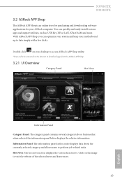
... your desktop to access ASRock APP Shop utility. *You need to be connected to the Internet to download apps from the ASRock APP Shop. 3.2.1 UI Overview Category Panel Hot News Information Panel Category Panel: he ASRock APP Shop is an online store for purchasing and downloading sotware applications for your motherboard up to perform job-related tasks. N3700-ITX N3150-ITX 3.2 ASRock APP Shop he category panel contains...
... your desktop to access ASRock APP Shop utility. *You need to be connected to the Internet to download apps from the ASRock APP Shop. 3.2.1 UI Overview Category Panel Hot News Information Panel Category Panel: he ASRock APP Shop is an online store for purchasing and downloading sotware applications for your motherboard up to perform job-related tasks. N3700-ITX N3150-ITX 3.2 ASRock APP Shop he category panel contains...
User Manual
Page 30
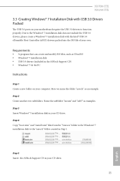
... USB 3.0 drivers, please create a Windows® 7 installation disk with USB 3.0 Drivers Packed he USB 3.0 ports on your CD drive. Name the subfolder "mount" and "usb3" as an example. Step 5 Insert the ASRock Support CD in Step 1. Step 4 Copy "boot.wim" and "install.wim" iles from the "Sources" folder in the Windows® 7 installation disk to function properly. N3700-ITX N3150-ITX 3.3 Creating Windows® 7 Installation Disk with the Intel® USB 3.0 eXtensible Host Controller (xHCI) drivers...
... USB 3.0 drivers, please create a Windows® 7 installation disk with USB 3.0 Drivers Packed he USB 3.0 ports on your CD drive. Name the subfolder "mount" and "usb3" as an example. Step 5 Insert the ASRock Support CD in Step 1. Step 4 Copy "boot.wim" and "install.wim" iles from the "Sources" folder in the Windows® 7 installation disk to function properly. N3700-ITX N3150-ITX 3.3 Creating Windows® 7 Installation Disk with the Intel® USB 3.0 eXtensible Host Controller (xHCI) drivers...
User Manual
Page 34
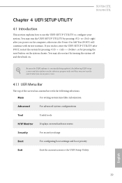
... reset button on the computer, otherwise, the Power-On-Self-Test (POST) will continue with the following selections: Main For setting system time/date information Advanced For advanced system conigurations Tool Useful tools H/W Monitor Displays current hardware status Security For security settings Boot For coniguring boot settings and boot priority Exit Exit the current screen or the UEFI Setup Utility English 29 Because the UEFI sotware is constantly being updated...
... reset button on the computer, otherwise, the Power-On-Self-Test (POST) will continue with the following selections: Main For setting system time/date information Advanced For advanced system conigurations Tool Useful tools H/W Monitor Displays current hardware status Security For security settings Boot For coniguring boot settings and boot priority Exit Exit the current screen or the UEFI Setup Utility English 29 Because the UEFI sotware is constantly being updated...

User Manual
Page 39
... Memory Conigure the size of memory that is installed. Onboard LAN Enable or disable the onboard network interface controller. 34 English Onboard HD Audio Enable/disable onboard HD audio. Front Panel Enable/disable front panel HD audio. 4.3.2 Chipset Coniguration DRAM Voltage Use this to the integrated graphics processor when the system boots up. Set to Auto to enable onboard HD audio and automatically disable it when a sound card is allocated to conigure DRAM Voltage. Primary Graphics Adapter Select a primary VGA. he default value is [Auto]. Onboard HDMI HD Audio Enable audio...
... Memory Conigure the size of memory that is installed. Onboard LAN Enable or disable the onboard network interface controller. 34 English Onboard HD Audio Enable/disable onboard HD audio. Front Panel Enable/disable front panel HD audio. 4.3.2 Chipset Coniguration DRAM Voltage Use this to the integrated graphics processor when the system boots up. Set to Auto to enable onboard HD audio and automatically disable it when a sound card is allocated to conigure DRAM Voltage. Primary Graphics Adapter Select a primary VGA. he default value is [Auto]. Onboard HDMI HD Audio Enable audio...

User Manual
Page 40
N3700-ITX N3150-ITX PCIE1 Link Speed Select the link speed for power saving when the computer is selected, the system will remain of the WiFi module. 35 English If [Power On] is shut down. Deep S5 Conigure deep sleep mode for PCIE1. WiFi Radio Enable or disable the connectivity of when the power recovers. Restore on AC/Power Loss Select the power state ater a power failure. If [Power Of] is selected, the power will start to boot up when the power recovers.
N3700-ITX N3150-ITX PCIE1 Link Speed Select the link speed for power saving when the computer is selected, the system will remain of the WiFi module. 35 English If [Power On] is shut down. Deep S5 Conigure deep sleep mode for PCIE1. WiFi Radio Enable or disable the connectivity of when the power recovers. Restore on AC/Power Loss Select the power state ater a power failure. If [Power Of] is selected, the power will start to boot up when the power recovers.

User Manual
Page 44
PS2 Y-Cable Enable the PS2 Y-Cable or set this option to Auto. 39 English 4.3.5 Super IO Coniguration N3700-ITX N3150-ITX Serial Port 1 Enable or disable the Serial port 1. Serial Port Address Select the address of the Serial port.
PS2 Y-Cable Enable the PS2 Y-Cable or set this option to Auto. 39 English 4.3.5 Super IO Coniguration N3700-ITX N3150-ITX Serial Port 1 Enable or disable the Serial port 1. Serial Port Address Select the address of the Serial port.

User Manual
Page 50
Network Coniguration Use this to download the UEFI irmware. 45 English N3700-ITX N3150-ITX Internet Setting Enable or disable sound efects in the setup utility. UEFI Download Server Select a server to conigure internet connection settings for Internet Flash.
Network Coniguration Use this to download the UEFI irmware. 45 English N3700-ITX N3150-ITX Internet Setting Enable or disable sound efects in the setup utility. UEFI Download Server Select a server to conigure internet connection settings for Internet Flash.
Quick Installation Guide
Page 7
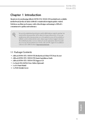
... and endurance. ASRock website http://www.asrock.com. 1.1 Package Contents • ASRock N3700-ITX / N3150-ITX Motherboard (Mini-ITX Form Factor) • ASRock N3700-ITX / N3150-ITX Quick Installation Guide • ASRock N3700-ITX / N3150-ITX Support CD • 2 x Serial ATA (SATA) Data Cables (Optional) • 1 x I/O Panel Shield • 1 x WiFi Module Screw 5 English You may ind the latest VGA cards and CPU support list on ASRock's website without notice. In case any modiications of this documentation occur, the updated version will be available...
... and endurance. ASRock website http://www.asrock.com. 1.1 Package Contents • ASRock N3700-ITX / N3150-ITX Motherboard (Mini-ITX Form Factor) • ASRock N3700-ITX / N3150-ITX Quick Installation Guide • ASRock N3700-ITX / N3150-ITX Support CD • 2 x Serial ATA (SATA) Data Cables (Optional) • 1 x I/O Panel Shield • 1 x WiFi Module Screw 5 English You may ind the latest VGA cards and CPU support list on ASRock's website without notice. In case any modiications of this documentation occur, the updated version will be available...

Quick Installation Guide
Page 10
You can use . 8 BIOS Feature Hardware Monitor OS Certiications • 1 x CPU Fan Connector (3-pin) • 1 x Chassis Fan Connector (3-pin) • 1 x 24 pin ATX Power Connector • 1 x Front Panel Audio Connector • 2 x USB 2.0 Headers (Support 4 USB 2.0 ports) (Supports ESD Protection (ASRock Full Spike Protection)) • 1 x USB 3.0 Header (Supports 2 USB 3.0 ports) (Supports ESD Protection (ASRock Full Spike Protection)) * USB3_3_4 is shared with USB_5_6. • 64Mb AMI UEFI Legal BIOS with GUI support • Supports Plug and Play • ACPI 1.1 compliant wake up ...
You can use . 8 BIOS Feature Hardware Monitor OS Certiications • 1 x CPU Fan Connector (3-pin) • 1 x Chassis Fan Connector (3-pin) • 1 x 24 pin ATX Power Connector • 1 x Front Panel Audio Connector • 2 x USB 2.0 Headers (Support 4 USB 2.0 ports) (Supports ESD Protection (ASRock Full Spike Protection)) • 1 x USB 3.0 Header (Supports 2 USB 3.0 ports) (Supports ESD Protection (ASRock Full Spike Protection)) * USB3_3_4 is shared with USB_5_6. • 64Mb AMI UEFI Legal BIOS with GUI support • Supports Plug and Play • ACPI 1.1 compliant wake up ...

Quick Installation Guide
Page 18
... AC'97 audio panel. his motherboard provides a 24-pin ATX power connector. Connect Mic_IN (MIC) to OUT2_L. C. E. If you use a 20-pin ATX power supply, please plug it to connect them for the HD audio panel only. Chassis Speaker Header (4-pin SPEAKER1) (see p.1, No. 10) Chassis Fan Connector (3-pin CHA_FAN1) (see p.1, No. 6) DUMMY SPEAKER 1 +5V DUMMY GND FAN_VOLTAGE FAN_SPEED CPU Fan Connector (3-pin CPU_FAN1) (see p.1, No. 1) FAN_SPEED FAN_VOLTAGE GND ATX Power Connector (24-pin ATXPWR1) (see p.1, No. 3) 12 24 1 13 Please connect the chassis speaker to the...
... AC'97 audio panel. his motherboard provides a 24-pin ATX power connector. Connect Mic_IN (MIC) to OUT2_L. C. E. If you use a 20-pin ATX power supply, please plug it to connect them for the HD audio panel only. Chassis Speaker Header (4-pin SPEAKER1) (see p.1, No. 10) Chassis Fan Connector (3-pin CHA_FAN1) (see p.1, No. 6) DUMMY SPEAKER 1 +5V DUMMY GND FAN_VOLTAGE FAN_SPEED CPU Fan Connector (3-pin CPU_FAN1) (see p.1, No. 1) FAN_SPEED FAN_VOLTAGE GND ATX Power Connector (24-pin ATXPWR1) (see p.1, No. 3) 12 24 1 13 Please connect the chassis speaker to the...
Quick Installation Guide
Page 123
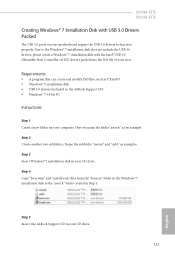
... in the Windows® 7 installation disk to the "asrock" folder created in the ASRock Support CD) • Windows® 7 64-bit PC Instructions Step 1 Create a new folder on your motherboard require the USB 3.0 drivers to the Windows® 7 installation disk does not include the USB 3.0 drivers, please create a Windows® 7 installation disk with USB 3.0 Drivers Packed he USB 3.0 ports on your computer. N3700-ITX N3150-ITX Creating Windows® 7 Installation Disk with the Intel® USB 3.0 eXtensible Host Controller (xHCI) drivers packed into...
... in the Windows® 7 installation disk to the "asrock" folder created in the ASRock Support CD) • Windows® 7 64-bit PC Instructions Step 1 Create a new folder on your motherboard require the USB 3.0 drivers to the Windows® 7 installation disk does not include the USB 3.0 drivers, please create a Windows® 7 installation disk with USB 3.0 Drivers Packed he USB 3.0 ports on your computer. N3700-ITX N3150-ITX Creating Windows® 7 Installation Disk with the Intel® USB 3.0 eXtensible Host Controller (xHCI) drivers packed into...


