Software/BIOS Setup Guide
Page 3
... 2 2.1 Auto Driver Installer (ADI) 2 2.1.1 Installing Drivers for the First Time 2 2.1.2 Updating Drivers 6 2.2 ASRock Live Update & APP Shop 7 2.2.1 Installing ASRock Live Update & APP Shop 7 2.2.2 UI Overview 8 2.2.3 Apps 9 2.2.4 BIOS & Drivers 12 2.2.5 Setting 13 2.3 ASRock Motherboard Utility (A-Tuning) 14 2.3.1 Installing ASRock Motherboard Utility (A-Tuning) 14 2.3.2 Using ASRock Motherboard Utility (A-Tuning) 14 Chapter 3 UEFI SETUP UTILITY 17 3.1 Introduction 17 3.1.1 Entering BIOS Setup 17 3.1.2 EZ Mode 18 3.1.3 Advanced Mode 19 3.1.4 UEFI Menu Bar...
... 2 2.1 Auto Driver Installer (ADI) 2 2.1.1 Installing Drivers for the First Time 2 2.1.2 Updating Drivers 6 2.2 ASRock Live Update & APP Shop 7 2.2.1 Installing ASRock Live Update & APP Shop 7 2.2.2 UI Overview 8 2.2.3 Apps 9 2.2.4 BIOS & Drivers 12 2.2.5 Setting 13 2.3 ASRock Motherboard Utility (A-Tuning) 14 2.3.1 Installing ASRock Motherboard Utility (A-Tuning) 14 2.3.2 Using ASRock Motherboard Utility (A-Tuning) 14 Chapter 3 UEFI SETUP UTILITY 17 3.1 Introduction 17 3.1.1 Entering BIOS Setup 17 3.1.2 EZ Mode 18 3.1.3 Advanced Mode 19 3.1.4 UEFI Menu Bar...
Software/BIOS Setup Guide
Page 5
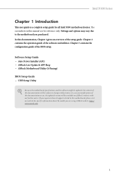
... the model you purchased. In case any modifications of the setup guide. Software Setup Guide • Auto Driver Installer (ADI) • ASRock Live Update & APP Shop • ASRock Motherboard Utility (A-Tuning) BIOS Setup Guide • UEFI Setup Utility Because the motherboard specifications and the software might be updated, the content of this manual are using. If you require technical support related to the motherboard you are for all Intel N100 motherboard series. The screenshots in this documentation will be subject to change...
... the model you purchased. In case any modifications of the setup guide. Software Setup Guide • Auto Driver Installer (ADI) • ASRock Live Update & APP Shop • ASRock Motherboard Utility (A-Tuning) BIOS Setup Guide • UEFI Setup Utility Because the motherboard specifications and the software might be updated, the content of this manual are using. If you require technical support related to the motherboard you are for all Intel N100 motherboard series. The screenshots in this documentation will be subject to change...
Software/BIOS Setup Guide
Page 6
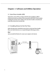
... download and install all necessary drivers automatically. 2.1.1 Installing Drivers for driver installation. Please note that the Internet access is no longer needed for the First Time Follow the instructions to the Internet. When you install the Windows OS, connect your computer to install all necessary drivers via the Auto Driver Installer. RJ-45 Cable LAN Port Modem Internet 2 ASRock motherboard already has its Ethernet driver prepacked in BIOS ROM. Chapter 2 Software and Utilities Operation 2.1 Auto Driver Installer (ADI) Optical drive or driver DVD...
... download and install all necessary drivers automatically. 2.1.1 Installing Drivers for driver installation. Please note that the Internet access is no longer needed for the First Time Follow the instructions to the Internet. When you install the Windows OS, connect your computer to install all necessary drivers via the Auto Driver Installer. RJ-45 Cable LAN Port Modem Internet 2 ASRock motherboard already has its Ethernet driver prepacked in BIOS ROM. Chapter 2 Software and Utilities Operation 2.1 Auto Driver Installer (ADI) Optical drive or driver DVD...
Software/BIOS Setup Guide
Page 7
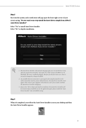
... then the Auto Driver Installer will be removed. If you boot into the system, and a notification will pop up in the lower right corner of your screen saying, "Do you would like to run the application again, please enable the "Auto Driver Installer" item in the BIOS setting. therefore, for using the Auto Driver Installer. Select "Yes" to skip the installation. 1. Now connect your desktop and then the Auto Driver Installer appears. 3
... then the Auto Driver Installer will be removed. If you boot into the system, and a notification will pop up in the lower right corner of your screen saying, "Do you would like to run the application again, please enable the "Auto Driver Installer" item in the BIOS setting. therefore, for using the Auto Driver Installer. Select "Yes" to skip the installation. 1. Now connect your desktop and then the Auto Driver Installer appears. 3

Software/BIOS Setup Guide
Page 9
... the "Tool" menu in the BIOS setting, and set the "Auto Driver Installer" item to complete the procedure. When driver installation is completed, the Auto Driver Installer tool will be uninstalled automatically from your system may reboot and continue installing remaining item(s)". After driver installation, the Auto Driver Installer will be removed. Click "No" to continue. For further drivers and utilities, please visit ASRock's website." Step 6 Once all drivers are successfully installed, a message pops...
... the "Tool" menu in the BIOS setting, and set the "Auto Driver Installer" item to complete the procedure. When driver installation is completed, the Auto Driver Installer tool will be uninstalled automatically from your system may reboot and continue installing remaining item(s)". After driver installation, the Auto Driver Installer will be removed. Click "No" to continue. For further drivers and utilities, please visit ASRock's website." Step 6 Once all drivers are successfully installed, a message pops...
Software/BIOS Setup Guide
Page 10
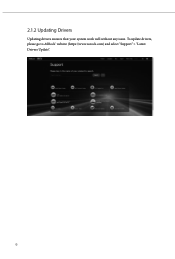
To update drivers, please go to ASRock' website (https://www.asrock.com) and select "Support" > "Latest Drivers Update". 6 2.1.2 Updating Drivers Updating drivers ensures that your system work well without any issue.
To update drivers, please go to ASRock' website (https://www.asrock.com) and select "Support" > "Latest Drivers Update". 6 2.1.2 Updating Drivers Updating drivers ensures that your system work well without any issue.
Software/BIOS Setup Guide
Page 21
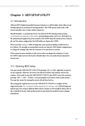
The battery on the motherboard supplies the power needed to configure all the supported system. You may cause system instability, mulfunction or boot failure. The UEFI system works with its test routines. We strongly recommend that inadequate BIOS settings may also restart by pressing the reset button on the computer; See your motherboard manual for instructions. 3.1.1 Entering BIOS Setup You may vary owing to enter the UEFI SETUP UTILITY after POST, restart the system by pressing...
The battery on the motherboard supplies the power needed to configure all the supported system. You may cause system instability, mulfunction or boot failure. The UEFI system works with its test routines. We strongly recommend that inadequate BIOS settings may also restart by pressing the reset button on the computer; See your motherboard manual for instructions. 3.1.1 Entering BIOS Setup You may vary owing to enter the UEFI SETUP UTILITY after POST, restart the system by pressing...
Software/BIOS Setup Guide
Page 27
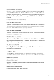
... N100 Series Intel Speed Shift Technology Allows you use the onboard graphics. To get the best support for hardware controlled P-states. When the limit is exceeded, the CPU ratio will still be lowered immediately. Long Duration Maintained Allows you have to configure the period of time. Configuration options: [Enabled] [Disabled] Long Duration Power Limit Allows you to allow for Intel Turbo Boost Max Technology 3.0 (ITBMT 3.0), you to enable Intel Speed Shift Technology...
... N100 Series Intel Speed Shift Technology Allows you use the onboard graphics. To get the best support for hardware controlled P-states. When the limit is exceeded, the CPU ratio will still be lowered immediately. Long Duration Maintained Allows you have to configure the period of time. Configuration options: [Enabled] [Disabled] Long Duration Power Limit Allows you to allow for Intel Turbo Boost Max Technology 3.0 (ITBMT 3.0), you to enable Intel Speed Shift Technology...
Software/BIOS Setup Guide
Page 35
...options: [Enabled] [Disabled] Reset for MRC Failed Reset system after MRC_DONE. Configuration options: [Auto] [Enabled] [Disabled] MRC Fast Boot When enabled, portions of memory reference code will use ASRock optimized value. When enabled, the memory timing will be executed when warm boot. Intel N100 Series Advanced Setting ASRock Timing Optimization Enable/Disable ASRock Timing Optimization. Configuration options: [Auto] [Slowest] Realtime Memory Timing Enable/Disable realtime memory timings. Configuration options: [Auto] [Enabled] [Disabled] Voltage Configuration Vcore Offset Voltage...
...options: [Enabled] [Disabled] Reset for MRC Failed Reset system after MRC_DONE. Configuration options: [Auto] [Enabled] [Disabled] MRC Fast Boot When enabled, portions of memory reference code will use ASRock optimized value. When enabled, the memory timing will be executed when warm boot. Intel N100 Series Advanced Setting ASRock Timing Optimization Enable/Disable ASRock Timing Optimization. Configuration options: [Auto] [Slowest] Realtime Memory Timing Enable/Disable realtime memory timings. Configuration options: [Auto] [Enabled] [Disabled] Voltage Configuration Vcore Offset Voltage...
Software/BIOS Setup Guide
Page 40
Configuration options: [Enabled] [Disabled] Intel AVX/AVX2 Allows you to enable or disable Hardware Prefetcher that automatically prefetches data and code for the processor. Configuration options: [Enabled] [Disabled] 36 Intel Virtualization Technology Intel Virtualization Technology allows a platform to run multiple operating systems and applications in C6 state. Configuration options: [Enabled] [Disabled] Intel ATX-512 Allows you to keep the CPU from overheating. This is applicable for Big Core only. Enable this item for better performance...
Configuration options: [Enabled] [Disabled] Intel AVX/AVX2 Allows you to enable or disable Hardware Prefetcher that automatically prefetches data and code for the processor. Configuration options: [Enabled] [Disabled] 36 Intel Virtualization Technology Intel Virtualization Technology allows a platform to run multiple operating systems and applications in C6 state. Configuration options: [Enabled] [Disabled] Intel ATX-512 Allows you to keep the CPU from overheating. This is applicable for Big Core only. Enable this item for better performance...
Software/BIOS Setup Guide
Page 42
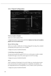
... Access Memory) If system has Resizable BAR capable PCIe Devices, use this option to enable or disable above 4G MemoryMappedIO decoding. Configuration options: [Enabled] [Disabled] VT-d Intel® Virtualization Technology for Directed I/O helps your motherboard.) Above 4G Decoding Allows you to 2048MB. Configuration options: [Auto] [Onboard] [PCIE1] (Options vary when you've installed a graphics card on your virtual machine monitor better utilize hardware by improving application compatibility and reliability, and providing additional levels of the system supports 64-bit PCI...
... Access Memory) If system has Resizable BAR capable PCIe Devices, use this option to enable or disable above 4G MemoryMappedIO decoding. Configuration options: [Enabled] [Disabled] VT-d Intel® Virtualization Technology for Directed I/O helps your motherboard.) Above 4G Decoding Allows you to 2048MB. Configuration options: [Auto] [Onboard] [PCIE1] (Options vary when you've installed a graphics card on your virtual machine monitor better utilize hardware by improving application compatibility and reliability, and providing additional levels of the system supports 64-bit PCI...
Software/BIOS Setup Guide
Page 43
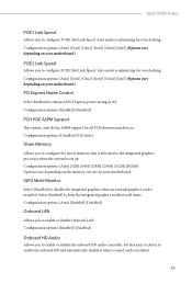
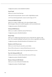
... card is allocated to enable or disable the onboard HD audio controller. Select [Enabled] to enable or disable Onboard LAN. Configuration options: [Enabled] [Disabled] Onboard HD Audio Allows you to configure the size of memory that is installed. Configuration options: [Disabled] [L1] [Auto] Share Memory Allows you to the integrated graphics processor when the system boots up. IGPU Multi-Monitor Select [Disabled] to configure PCIE2 Slot Link Speed. Configuration options: [Enabled] [Disabled] PCH PCIE ASPM Support This option controls the ASPM support for overclocking...
... card is allocated to enable or disable the onboard HD audio controller. Select [Enabled] to enable or disable Onboard LAN. Configuration options: [Enabled] [Disabled] Onboard HD Audio Allows you to configure the size of memory that is installed. Configuration options: [Disabled] [L1] [Auto] Share Memory Allows you to the integrated graphics processor when the system boots up. IGPU Multi-Monitor Select [Disabled] to configure PCIE2 Slot Link Speed. Configuration options: [Enabled] [Disabled] PCH PCIE ASPM Support This option controls the ASPM support for overclocking...
Software/BIOS Setup Guide
Page 44
... Device Allows you to configure deep sleep mode for better system compatibility and stability. Deep Sleep Allows you to enable or disable the onboard WAN device. Configuration options: [Auto] [Enabled] [Disabled] Front Panel Allows you to select Front Panel type. [HD] sets the front panel audio connector mode to high definition audio. [AC 97] sets the front panel audio connector mode to legacy AC'97.] Onboard HDMI HD Audio Allows you to select the power state after a power failure. [Power Off] sets the power to remain off the Onboard LED in the ACPI...
... Device Allows you to configure deep sleep mode for better system compatibility and stability. Deep Sleep Allows you to enable or disable the onboard WAN device. Configuration options: [Auto] [Enabled] [Disabled] Front Panel Allows you to select Front Panel type. [HD] sets the front panel audio connector mode to high definition audio. [AC 97] sets the front panel audio connector mode to legacy AC'97.] Onboard HDMI HD Audio Allows you to select the power state after a power failure. [Power Off] sets the power to remain off the Onboard LED in the ACPI...
Software/BIOS Setup Guide
Page 45
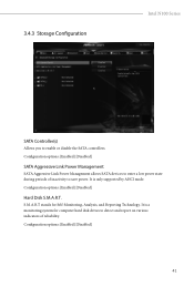
...a low power state during periods of reliability. Configuration options: [Enabled] [Disabled] Hard Disk S.M.A.R.T. S.M.A.R.T stands for computer hard disk drives to detect and report on various indicators of inactivity to save power. It is a monitoring system for Self-Monitoring, Analysis, and Reporting Technology. Configuration options: [Enabled] [Disabled] SATA Aggressive Link Power Management SATA Aggressive Link Power Management allows SATA devices to enable or disable the SATA controllers. Configuration options: [Enabled] [Disabled] 41 It is only supported by AHCI mode.
...a low power state during periods of reliability. Configuration options: [Enabled] [Disabled] Hard Disk S.M.A.R.T. S.M.A.R.T stands for computer hard disk drives to detect and report on various indicators of inactivity to save power. It is a monitoring system for Self-Monitoring, Analysis, and Reporting Technology. Configuration options: [Enabled] [Disabled] SATA Aggressive Link Power Management SATA Aggressive Link Power Management allows SATA devices to enable or disable the SATA controllers. Configuration options: [Enabled] [Disabled] 41 It is only supported by AHCI mode.
Software/BIOS Setup Guide
Page 49
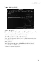
... for the motherboard that supports the PS/2 port. [Auto] disables legacy support if no USB devices are connected. [Disabled] keeps USB devices available only for OSes without XHCI hand-off This is a workaround for EFI applications. [UEFI Setup Only] sets to enable or disable Legacy OS Support for USB devices. Configuration options: [Enabled] [Disabled] 45 XHCI Hand-off support. The XHCI ownership change should be claimed by XHCI driver. 3.4.6 USB Configuration Intel N100 Series Legacy USB Support Allows you to support USB devices under the UEFI setup and Windows/Linux operating...
... for the motherboard that supports the PS/2 port. [Auto] disables legacy support if no USB devices are connected. [Disabled] keeps USB devices available only for OSes without XHCI hand-off This is a workaround for EFI applications. [UEFI Setup Only] sets to enable or disable Legacy OS Support for USB devices. Configuration options: [Enabled] [Disabled] 45 XHCI Hand-off support. The XHCI ownership change should be claimed by XHCI driver. 3.4.6 USB Configuration Intel N100 Series Legacy USB Support Allows you to support USB devices under the UEFI setup and Windows/Linux operating...
Software/BIOS Setup Guide
Page 52
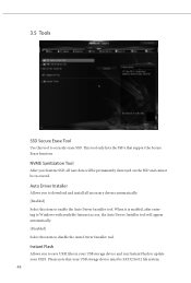
... Auto Driver Installer tool. Pleaes note that support the Secure Erase function. This tool only lists the SSDs that your USB storage device must be recovered. Auto Driver Installer Allows you to save UEFI files in your USB storage device and run Instant Flash to securely erase SSD. When it is enabled, after entering to Windows with available Internet access, the Auto Driver Installer tool will appear automatically. [Disabled] Select this item to download and install all user...
... Auto Driver Installer tool. Pleaes note that support the Secure Erase function. This tool only lists the SSDs that your USB storage device must be recovered. Auto Driver Installer Allows you to save UEFI files in your USB storage device and run Instant Flash to securely erase SSD. When it is enabled, after entering to Windows with available Internet access, the Auto Driver Installer tool will appear automatically. [Disabled] Select this item to download and install all user...
Software/BIOS Setup Guide
Page 58
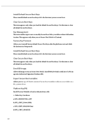
Use this item to install factory default Secure Boot keys after the platform reset and while the System is in Setup mode. Public Key Certificate: a) EFI_SIGNATURE_LIST b) EFI_CERT_X509 (DER) c) EFI_CERT_RSA2048 (bin) d) EFI_CERT_SHAXXX 54 This appears only when you set Secure Boot Mode to clear all default Secure Boot keys. Install Default Secure Boot Keys Please install default secure boot keys if it 's the first time you use secure boot. Enroll SHA256 Hash certificate of Secure Boot variables to copy...
Use this item to install factory default Secure Boot keys after the platform reset and while the System is in Setup mode. Public Key Certificate: a) EFI_SIGNATURE_LIST b) EFI_CERT_X509 (DER) c) EFI_CERT_RSA2048 (bin) d) EFI_CERT_SHAXXX 54 This appears only when you set Secure Boot Mode to clear all default Secure Boot keys. Install Default Secure Boot Keys Please install default secure boot keys if it 's the first time you use secure boot. Enroll SHA256 Hash certificate of Secure Boot variables to copy...
User Manual
Page 3
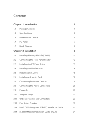
...1.2 Specifications 2 1.3 Motherboard Layout 5 1.4 I/O Panel 7 1.5 Block Diagram 8 Chapter 2 Installation 9 2.1 Installing Memory Module (DIMM) 10 2.2 Connecting the Front Panel Header 12 2.3 Installing the I/O Panel Shield 13 2.4 Installing the Motherboard 14 2.5 Installing SATA Drives 15 2.6 Installing a Graphics Card 17 2.7 Connecting Peripheral Devices 19 2.8 Connecting the Power Connectors 20 2.9 Power On 21 2.10 Jumpers Setup 22 2.11 Onboard Headers and Connectors 23 2.12 Post Status Checker 31 2.13 Intel® CNVi (Integrated WiFi/BT) Installation Guide...
...1.2 Specifications 2 1.3 Motherboard Layout 5 1.4 I/O Panel 7 1.5 Block Diagram 8 Chapter 2 Installation 9 2.1 Installing Memory Module (DIMM) 10 2.2 Connecting the Front Panel Header 12 2.3 Installing the I/O Panel Shield 13 2.4 Installing the Motherboard 14 2.5 Installing SATA Drives 15 2.6 Installing a Graphics Card 17 2.7 Connecting Peripheral Devices 19 2.8 Connecting the Power Connectors 20 2.9 Power On 21 2.10 Jumpers Setup 22 2.11 Onboard Headers and Connectors 23 2.12 Post Status Checker 31 2.13 Intel® CNVi (Integrated WiFi/BT) Installation Guide...
User Manual
Page 6
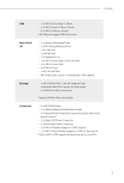
...-45 LAN Port • HD Audio Jacks: Line in / Front Speaker / Microphone Storage • 1 x M.2 Socket (M2_1, Key M), supports type 2242/2260/2280 PCIe Gen3x2 (16 Gb/s) mode* • 2 x SATA3 6.0 Gb/s Connectors * Supports NVMe SSD as boot disks Connector • 1 x SPI TPM Header • 1 x Chassis Intrusion and Speaker Header • 2 x Chassis/Water Pump Fan Connectors (4-pin) (Smart Fan Speed Control)* • 1 x 24 pin ATX Power Connector • 1 x Front Panel Audio Connector • 2 x USB 2.0 Headers (Support 4 USB 2.0 ports) • 1 x USB 3.2 Gen1 Header (Supports 2 USB...
...-45 LAN Port • HD Audio Jacks: Line in / Front Speaker / Microphone Storage • 1 x M.2 Socket (M2_1, Key M), supports type 2242/2260/2280 PCIe Gen3x2 (16 Gb/s) mode* • 2 x SATA3 6.0 Gb/s Connectors * Supports NVMe SSD as boot disks Connector • 1 x SPI TPM Header • 1 x Chassis Intrusion and Speaker Header • 2 x Chassis/Water Pump Fan Connectors (4-pin) (Smart Fan Speed Control)* • 1 x 24 pin ATX Power Connector • 1 x Front Panel Audio Connector • 2 x USB 2.0 Headers (Support 4 USB 2.0 ports) • 1 x USB 3.2 Gen1 Header (Supports 2 USB...
User Manual
Page 9
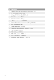
Description 1 Chassis/Water Pump Fan Connector (CHA_FAN1/WP) 2 SPI TPM Header (SPI_TPM_J1) 3 288-pin DDR4 DIMM Slot (DDR4_A1) 4 SATA3 Connector (SATA3_0) 5 SATA3 Connector (SATA3_1) 6 ATX Power Connector (ATXPWR1) 7 Chassis/Water Pump Fan Connector (CHA_FAN2/WP) 8 Post Status Checker (PSC) 9 System Panel Header (PANEL1) 10 Chassis Intrusion and Speaker Header (SPK_CI1) 11 USB 2.0 Header (USB_78) 12 USB 2.0 Header (USB_56) 13 USB 3.2 Gen1 Header (USB32_34) 14 Clear CMOS Jumper (CLRMOS1) 15 Front Panel Audio Header (HD_AUDIO1) 6 No.
Description 1 Chassis/Water Pump Fan Connector (CHA_FAN1/WP) 2 SPI TPM Header (SPI_TPM_J1) 3 288-pin DDR4 DIMM Slot (DDR4_A1) 4 SATA3 Connector (SATA3_0) 5 SATA3 Connector (SATA3_1) 6 ATX Power Connector (ATXPWR1) 7 Chassis/Water Pump Fan Connector (CHA_FAN2/WP) 8 Post Status Checker (PSC) 9 System Panel Header (PANEL1) 10 Chassis Intrusion and Speaker Header (SPK_CI1) 11 USB 2.0 Header (USB_78) 12 USB 2.0 Header (USB_56) 13 USB 3.2 Gen1 Header (USB32_34) 14 Clear CMOS Jumper (CLRMOS1) 15 Front Panel Audio Header (HD_AUDIO1) 6 No.


