User Manual
Page 3
... CPU Installation 10 2.4 Installation of CPU fan and Heatsink 10 2.5 Installation of Memory Modules (DIMM 11 2.6 Expansion Slots 11 2.7 Jumpers Setup 12 2.8 Connectors 13 3 BIOS Setup 15 3.1 BIOS Setup Utility 15 3.2 BIOS Setup Utility Main Menu 15 3.3 Legend Bar 16 3.4 Standard CMOS Setup 16 3.5 Advanced CMOS Setup 19 3.6 Advanced Chipset Setup 20 3.7 Power Management Setup 22 3.8 PCI / Plug and Play Setup 23 3.9 Peripheral Setup 24 3.10 Hardware Monitor Setup 26 3.11 Change Supervisor Password / Change User Password ..... 26 3.12 Auto Configuration with Optimal Settings 26...
... CPU Installation 10 2.4 Installation of CPU fan and Heatsink 10 2.5 Installation of Memory Modules (DIMM 11 2.6 Expansion Slots 11 2.7 Jumpers Setup 12 2.8 Connectors 13 3 BIOS Setup 15 3.1 BIOS Setup Utility 15 3.2 BIOS Setup Utility Main Menu 15 3.3 Legend Bar 16 3.4 Standard CMOS Setup 16 3.5 Advanced CMOS Setup 19 3.6 Advanced Chipset Setup 20 3.7 Power Management Setup 22 3.8 PCI / Plug and Play Setup 23 3.9 Peripheral Setup 24 3.10 Hardware Monitor Setup 26 3.11 Change Supervisor Password / Change User Password ..... 26 3.12 Auto Configuration with Optimal Settings 26...
User Manual
Page 4
....1 cm) ASRock M266A Quick Installation Guide ASRock Intel-VIA Support CD 1 Cable for IDE devices (1 x ATA 66/100/133) 1 Cable for new DIY system builders. Because the motherboard specifications and the BIOS software might be updated, the content of this manual contain introduction of this manual will be subject to quality and endurance. Chapter 1 and 2 of the motherboard and step-bystep installation guide for floppy drive (1 x ribbon cable) 1 ASRock I/O shield 1 COM port bracket 1 ASRock MR card (optional) 4 Chapter...
....1 cm) ASRock M266A Quick Installation Guide ASRock Intel-VIA Support CD 1 Cable for IDE devices (1 x ATA 66/100/133) 1 Cable for new DIY system builders. Because the motherboard specifications and the BIOS software might be updated, the content of this manual contain introduction of this manual will be subject to quality and endurance. Chapter 1 and 2 of the motherboard and step-bystep installation guide for floppy drive (1 x ribbon cable) 1 ASRock I/O shield 1 COM port bracket 1 ASRock MR card (optional) 4 Chapter...
User Manual
Page 5
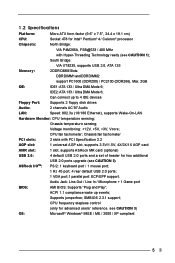
.../ Ultra DMA Mode 6; Chassis temperature sensing; ACPI 1.1 compliance wake up to 4 IDE devices Floppy Port: Supports 2 floppy disk drives Audio: 2 channels AC'97 Audio LAN: Speed: 802.3u (10/100 Ethernet), supports Wake-On-LAN Hardware Monitor: CPU temperature sensing; CPU frequency stepless control (only for two additional ASRock I/OTM: USB 2.0 ports upgrade (see CAUTION 2) PS/2: 1 keyboard port / 1 mouse port; 1 RJ 45 port; 4 rear default USB 2.0 ports; 1 VGA port;1 parallel port: ECP/EPP support; Chassis fan tachometer PCI slots: 2 slots with Hyper-Threading Technology ready...
.../ Ultra DMA Mode 6; Chassis temperature sensing; ACPI 1.1 compliance wake up to 4 IDE devices Floppy Port: Supports 2 floppy disk drives Audio: 2 channels AC'97 Audio LAN: Speed: 802.3u (10/100 Ethernet), supports Wake-On-LAN Hardware Monitor: CPU temperature sensing; CPU frequency stepless control (only for two additional ASRock I/OTM: USB 2.0 ports upgrade (see CAUTION 2) PS/2: 1 keyboard port / 1 mouse port; 1 RJ 45 port; 4 rear default USB 2.0 ports; 1 VGA port;1 parallel port: ECP/EPP support; Chassis fan tachometer PCI slots: 2 slots with Hyper-Threading Technology ready...
User Manual
Page 6
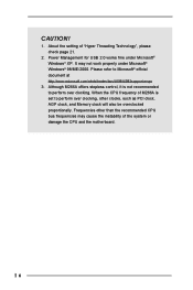
... Threading Technology", please check page 21. 2. Frequencies other clocks, such as PCI clock, AGP clock, and Memory clock will also be overclocked proportionally. About the setting of the system or damage the CPU and the motherboard. 6 Although M266A offers stepless control, it is set to Microsoft® official document at http://www.microsoft.com/whdc/hwdev/bus/USB/USB2support.mspx 3. Power Management for USB 2.0 works fine under Microsoft® Windows®...
... Threading Technology", please check page 21. 2. Frequencies other clocks, such as PCI clock, AGP clock, and Memory clock will also be overclocked proportionally. About the setting of the system or damage the CPU and the motherboard. 6 Although M266A offers stepless control, it is set to Microsoft® official document at http://www.microsoft.com/whdc/hwdev/bus/USB/USB2support.mspx 3. Power Management for USB 2.0 works fine under Microsoft® Windows®...
User Manual
Page 7
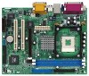
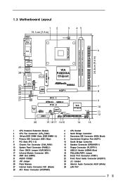
...) 9 PCI Slots (PCI 1- 2) 11 Chassis Fan Connector (CHA_FAN1) 13 System Panel Connector (PANEL1) 15 Clear CMOS Jumper (CLRCMOS1) 17 Infrared Module Connector (IR1) 19 AMR Slot (AMR1) 21 AUDIO CODEC 23 JR1 Jumper 25 Flash Memory 27 Internal Audio Connector: CD1 (Black) 29 ATX Power Connector (ATXPWR1) 2 CPU Socket 4 North Bridge Controller 6 Secondary IDE Connector (IDE2, Black) 8 Accelerated Graphics Port (AGP1) 10 South Bridge Controller 12 Speaker Connector (SPEAKER 1) 14 Floppy Connector (FLOPPY1) 16 USB 2.0 Header (USB45, Blue) 18 PS2_USB_PWR1 Jumper 20 Serial Port...
...) 9 PCI Slots (PCI 1- 2) 11 Chassis Fan Connector (CHA_FAN1) 13 System Panel Connector (PANEL1) 15 Clear CMOS Jumper (CLRCMOS1) 17 Infrared Module Connector (IR1) 19 AMR Slot (AMR1) 21 AUDIO CODEC 23 JR1 Jumper 25 Flash Memory 27 Internal Audio Connector: CD1 (Black) 29 ATX Power Connector (ATXPWR1) 2 CPU Socket 4 North Bridge Controller 6 Secondary IDE Connector (IDE2, Black) 8 Accelerated Graphics Port (AGP1) 10 South Bridge Controller 12 Speaker Connector (SPEAKER 1) 14 Floppy Connector (FLOPPY1) 16 USB 2.0 Header (USB45, Blue) 18 PS2_USB_PWR1 Jumper 20 Serial Port...
User Manual
Page 9
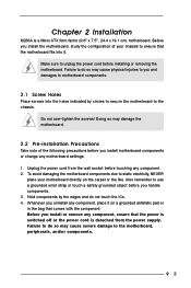
... 2 Installation M266A is detached from the wall socket before installing or removing the motherboard. Unplug the power cord from the power supply. Failure to you uninstall any component. 2. Do not over-tighten the screws! Before you install the motherboard, study the configuration of the following precautions before you install motherboard components or change any component, ensure that comes with the component. Before you install or remove any motherboard settings. 1. To...
... 2 Installation M266A is detached from the wall socket before installing or removing the motherboard. Unplug the power cord from the power supply. Failure to you uninstall any component. 2. Do not over-tighten the screws! Before you install the motherboard, study the configuration of the following precautions before you install motherboard components or change any component, ensure that comes with the component. Before you install or remove any motherboard settings. 1. To...
User Manual
Page 11
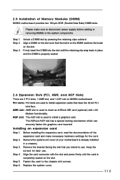
... M266A motherboard. Fasten the card to use . Installing an expansion card Step 1. Keep the screws for the card. 2.5 Installation of the expansion card and make sure to disconnect power supply before adding or removing DIMMs or the system components. The ASRock AGP slot has a special locking mechanism which can securely fasten the graphics card inserted. Step 2. Align a DIMM on the slot such that have the 32-bit PCI interface. Replace...
... M266A motherboard. Fasten the card to use . Installing an expansion card Step 1. Keep the screws for the card. 2.5 Installation of the expansion card and make sure to disconnect power supply before adding or removing DIMMs or the system components. The ASRock AGP slot has a special locking mechanism which can securely fasten the graphics card inserted. Step 2. Align a DIMM on the slot such that have the 32-bit PCI interface. Replace...
User Manual
Page 12
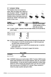
... front panel and rear panel audio connectors can work. 2. JR1(see p.7 item 23) JL1(see p.7 item 15) Clear CMOS 2-pin jumper Note: CLRCMOS1 allows you connect speakers in CMOS. 2.7 Jumpers Setup The illustration shows how jumpers are "SHORT" when jumper cap is placed on these 2 pins. The data in CMOS includes system setup information such as system password, date, time, and system setup parameters. To clear and reset the system parameters to default setup, please turn off...
... front panel and rear panel audio connectors can work. 2. JR1(see p.7 item 23) JL1(see p.7 item 15) Clear CMOS 2-pin jumper Note: CLRCMOS1 allows you connect speakers in CMOS. 2.7 Jumpers Setup The illustration shows how jumpers are "SHORT" when jumper cap is placed on these 2 pins. The data in CMOS includes system setup information such as system password, date, time, and system setup parameters. To clear and reset the system parameters to default setup, please turn off...
User Manual
Page 14
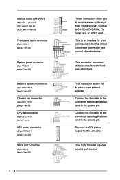
... front panel functions. Connect the fan cable to the connector matching the black wire to an external speaker. Serial port connector (9-pin COM1) (see p.7 item 13) GND +5VA BACKOUT-R BACKOUT-L 1 A U D - Internal audio connectors (4-pin CD1, 4-pin AUX1) (CD1: see p.7 item 27) (AUX1: see p.7 item 26) These connectors allow you to attach to the ground pin. O U T- Connect an ATX power supply to receive stereo audio input from sound sources such as AUX1 a CD-ROM, DVD-ROM, TV tuner card...
... front panel functions. Connect the fan cable to the connector matching the black wire to an external speaker. Serial port connector (9-pin COM1) (see p.7 item 13) GND +5VA BACKOUT-R BACKOUT-L 1 A U D - Internal audio connectors (4-pin CD1, 4-pin AUX1) (CD1: see p.7 item 27) (AUX1: see p.7 item 26) These connectors allow you to attach to the ground pin. O U T- Connect an ATX power supply to receive stereo audio input from sound sources such as AUX1 a CD-ROM, DVD-ROM, TV tuner card...
User Manual
Page 15
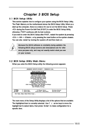
... configure your screen. 3.2 BIOS Setup Utility Main Menu When you to run the BIOS Setup. Use arrow keys to move the highlight bar to select items, then press to enter the BIOS Setup after POST, restart the system by pressing + + , or by turning the system off and then back on the motherboard stores the BIOS Setup Utility. VERSION 3.31a M266 (A) BIOS P1.50 Standard CMOS Setup Advanced CMOS Setup Advanced Chipset Setup Power Management Setup PCI / Plug and Play Setup Peripheral Setup Hardware Monitor Setup Change Supervisor Password Change User Password Auto Configuration...
... configure your screen. 3.2 BIOS Setup Utility Main Menu When you to run the BIOS Setup. Use arrow keys to move the highlight bar to select items, then press to enter the BIOS Setup after POST, restart the system by pressing + + , or by turning the system off and then back on the motherboard stores the BIOS Setup Utility. VERSION 3.31a M266 (A) BIOS P1.50 Standard CMOS Setup Advanced CMOS Setup Advanced Chipset Setup Power Management Setup PCI / Plug and Play Setup Peripheral Setup Hardware Monitor Setup Change Supervisor Password Change User Password Auto Configuration...
User Manual
Page 16
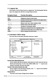
... fields. VERSION 3.31a Standard CMOS Setup [ Setup Help ] System Date System Time Floppy Drives IDE Devices Jul 08 2003 Tue 20:07:40 Month: Jan - System Time [Hour:Minute:Second] Set the system to 2099). AMIBIOS SETUP UTILITY - Valid values for a highlighted field Loads all the setup items to set the type of all the Setup Screen is a legend bar. Use keys to move between fields Selects menu to the...
... fields. VERSION 3.31a Standard CMOS Setup [ Setup Help ] System Date System Time Floppy Drives IDE Devices Jul 08 2003 Tue 20:07:40 Month: Jan - System Time [Hour:Minute:Second] Set the system to 2099). AMIBIOS SETUP UTILITY - Valid values for a highlighted field Loads all the setup items to set the type of all the Setup Screen is a legend bar. Use keys to move between fields Selects menu to the...
User Manual
Page 17
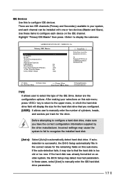
... configuration options. Use these cases, select [User] to configure IDE devices. F1:Help Esc:Previous Menu :Select Item +/-:Change Values Enter:Select Sub-Menu F9:Setup Defaults F10:Save & Exit TYPE It allows user to automatically detect hard disk drive. Incorrect settings may cause the system to fail to recognize the installed hard disk. [Auto]: Select [Auto] to select the type of drive, Or Select [AUTO] to that you have the correct configuration information supplied by the drive manufacturer. If the hard disk...
... configuration options. Use these cases, select [User] to configure IDE devices. F1:Help Esc:Previous Menu :Select Item +/-:Change Values Enter:Select Sub-Menu F9:Setup Defaults F10:Save & Exit TYPE It allows user to automatically detect hard disk drive. Incorrect settings may cause the system to fail to recognize the installed hard disk. [Auto]: Select [Auto] to select the type of drive, Or Select [AUTO] to that you have the correct configuration information supplied by the drive manufacturer. If the hard disk...
User Manual
Page 19
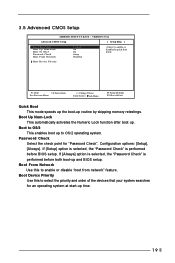
... before both boot-up to select the priority and order of the devices that your system searches for "Password Check". Boot Device Priority F1:Help Esc:Previous Menu :Select Item +/-:Change Values Enter:Select Sub-Menu F9:Setup Defaults F10:Save & Exit Quick Boot This mode speeds up the boot-up . 3.5 Advanced CMOS Setup AMIBIOS SETUP UTILITY - If [Setup] option is selected, the "Password Check" is performed before BIOS setup. Boot to enable or disable the quick boot mode.
... before both boot-up to select the priority and order of the devices that your system searches for "Password Check". Boot Device Priority F1:Help Esc:Previous Menu :Select Item +/-:Change Values Enter:Select Sub-Menu F9:Setup Defaults F10:Save & Exit Quick Boot This mode speeds up the boot-up . 3.5 Advanced CMOS Setup AMIBIOS SETUP UTILITY - If [Setup] option is selected, the "Password Check" is performed before BIOS setup. Boot to enable or disable the quick boot mode.
User Manual
Page 20
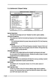
... set the front side bus frequency for graphics memory. CPU Host Frequency This allows you leave this is selected, the motherboard will equal the core speed of spread spectrum. Wrong setup may also choose 1X or 2X for older version of the PCI memory address range used for the installed processor. [Auto] The motherboard detects the jumper setup and sets the CPU host frequency automatically. [Manual] This allows user to a section of VGA cards. 3.6 Advanced Chipset Setup AMIBIOS SETUP UTILITY - AGP Mode The default...
... set the front side bus frequency for graphics memory. CPU Host Frequency This allows you leave this is selected, the motherboard will equal the core speed of spread spectrum. Wrong setup may also choose 1X or 2X for older version of the PCI memory address range used for the installed processor. [Auto] The motherboard detects the jumper setup and sets the CPU host frequency automatically. [Manual] This allows user to a section of VGA cards. 3.6 Advanced Chipset Setup AMIBIOS SETUP UTILITY - AGP Mode The default...
User Manual
Page 21
... system stability. CPU R/W DRAM 0WS The default is selected. Leave on the default value for this to enable or disable support to enable or disable the use of USB controller. Set to select the size of share memory is [Disabled]. USB Controller Use this feature when using Microsoft® Windows® XP, or Linux kernel version 2.4.18 or higher. OnBoard VGA will get better resolution if larger size of share memory for onboard VGA. PCI Delay Transaction Enable PCI Delay Transaction...
... system stability. CPU R/W DRAM 0WS The default is selected. Leave on the default value for this to enable or disable support to enable or disable the use of USB controller. Set to select the size of share memory is [Disabled]. USB Controller Use this feature when using Microsoft® Windows® XP, or Linux kernel version 2.4.18 or higher. OnBoard VGA will get better resolution if larger size of share memory for onboard VGA. PCI Delay Transaction Enable PCI Delay Transaction...

User Manual
Page 22
... Keyboard Power On Use this to enable or disable keyboard to set the power state after an unexpected AC power loss. If [Enabled] is selected, the AC power resumes and the system starts to boot up time you to select auto-detect or disable the STR feature. 3.7 Power Management Setup AMIBIOS SETUP UTILITY - Restore on the system. Select [Auto] will enable this to enable or disable PCI devices to turn on AC/Power Loss Ring-In Power On PCI Devices Power...
... Keyboard Power On Use this to enable or disable keyboard to set the power state after an unexpected AC power loss. If [Enabled] is selected, the AC power resumes and the system starts to boot up time you to select auto-detect or disable the STR feature. 3.7 Power Management Setup AMIBIOS SETUP UTILITY - Restore on the system. Select [Auto] will enable this to enable or disable PCI devices to turn on AC/Power Loss Ring-In Power On PCI Devices Power...
User Manual
Page 24
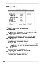
..."EPP Version". OnBoard Game Port Select address for Game Port or disable Game Port. 3.9 Peripheral Setup AMIBIOS SETUP UTILITY - Configuration options: [Auto], [Disabled], [378], [278]. Configuration options: [Disabled], [200h], [208h]. 24 Parallel Port Mode Set the operation mode of the parallel port. OnBoard Infrared Port This allows you to enable or disable the floppy drive controller. The default value is [ECP+EPP]. F1:Help Esc:Previous Menu :Select Item +/-:Change Values Enter:Select Sub-Menu F9:Setup Defaults F10:Save & Exit OnBoard FDC Use this option is installed...
..."EPP Version". OnBoard Game Port Select address for Game Port or disable Game Port. 3.9 Peripheral Setup AMIBIOS SETUP UTILITY - Configuration options: [Auto], [Disabled], [378], [278]. Configuration options: [Disabled], [200h], [208h]. 24 Parallel Port Mode Set the operation mode of the parallel port. OnBoard Infrared Port This allows you to enable or disable the floppy drive controller. The default value is [ECP+EPP]. F1:Help Esc:Previous Menu :Select Item +/-:Change Values Enter:Select Sub-Menu F9:Setup Defaults F10:Save & Exit OnBoard FDC Use this option is installed...
User Manual
Page 25
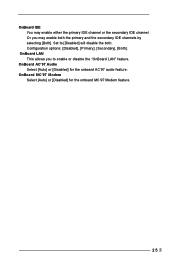
OnBoard MC'97 Modem Select [Auto] or [Disabled] for the onboard AC'97 audio feature. Or you to [Disabled] will disable the both the primary and the secondary IDE channels by selecting [Both]. OnBoard LAN This allows you may enable either the primary IDE channel or the secondary IDE channel. OnBoard IDE You may enable both . Configuration options: [Disabled], [Primary], [Secondary], [Both]. OnBoard AC'97 Audio Select [Auto] or [Disabled] for the onboard MC'97 Modem feature. 25 Set to enable or disable the "OnBoard LAN" feature.
OnBoard MC'97 Modem Select [Auto] or [Disabled] for the onboard AC'97 audio feature. Or you to [Disabled] will disable the both the primary and the secondary IDE channels by selecting [Both]. OnBoard LAN This allows you may enable either the primary IDE channel or the secondary IDE channel. OnBoard IDE You may enable both . Configuration options: [Disabled], [Primary], [Secondary], [Both]. OnBoard AC'97 Audio Select [Auto] or [Disabled] for the onboard MC'97 Modem feature. 25 Set to enable or disable the "OnBoard LAN" feature.
User Manual
Page 26
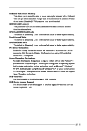
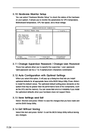
... Optimal Settings When you install optimized defaults for CPU temperature, Motherboard temperature, CPU fan speed, and critical voltage. VERSION 3.31a Hardware Monitor Setup [ Setup Help ] CPU Temperature M / B Temperature CPU FAN Speed Chassis Fan Speed Vcore + 3.30V + 5.00V + 12.00V 35 C / 95 F 27 C / 82 F 3110 RPM 0 RPM 1.72 V 3.31 V 4.97 V 12.16 V F1:Help Esc:Previous Menu :Select Item +/-:Change Values Enter:Select Sub-Menu F9:Setup Defaults F10:Save & Exit 3.11 Change Supervisor Password / Change User Password These two options allow you to exit the BIOS Setup Utility without...
... Optimal Settings When you install optimized defaults for CPU temperature, Motherboard temperature, CPU fan speed, and critical voltage. VERSION 3.31a Hardware Monitor Setup [ Setup Help ] CPU Temperature M / B Temperature CPU FAN Speed Chassis Fan Speed Vcore + 3.30V + 5.00V + 12.00V 35 C / 95 F 27 C / 82 F 3110 RPM 0 RPM 1.72 V 3.31 V 4.97 V 12.16 V F1:Help Esc:Previous Menu :Select Item +/-:Change Values Enter:Select Sub-Menu F9:Setup Defaults F10:Save & Exit 3.11 Change Supervisor Password / Change User Password These two options allow you to exit the BIOS Setup Utility without...
User Manual
Page 27
... the motherboard contains necessary drivers and useful utilities that the motherboard supports. Because motherboard settings and hardware options vary, use the setup procedures in your dealer for general reference only. Chapter 4 Software Support 4.1 Install Operating System This motherboard supports various Microsoft® Windows® operating systems: 98 SE/ ME/ 2000/ XP. You can run Microsoft® Media Player® to activate the devices. 4.2.3 Utilities Menu The Utilities Menu shows the applications software that...
... the motherboard contains necessary drivers and useful utilities that the motherboard supports. Because motherboard settings and hardware options vary, use the setup procedures in your dealer for general reference only. Chapter 4 Software Support 4.1 Install Operating System This motherboard supports various Microsoft® Windows® operating systems: 98 SE/ ME/ 2000/ XP. You can run Microsoft® Media Player® to activate the devices. 4.2.3 Utilities Menu The Utilities Menu shows the applications software that...


