User Manual
Page 3
... Screen 35 3.5 Boot Screen 35 3.5.1 Boot Settings Configuration 36 3 Installation 10 Pre-installation Precautions 10 2.1 CPU Installation 11 2.2 Installation of CPU Fan and Heatsink 11 2.3 Installation of Memory Modules (DIMM 12 2.4 Expansion Slots (Future CPU Port, PCI, AGP, and AMR Slots) ....... 13 2.5 Jumpers Setup 15 2.6 Onboard Headers and Connectors ... 20 2.10 Installing Windows 98 / ME / 2000 / XP / XP 64-bit Without RAID Functions 21 3 . Introduction 5 1.1 Package Contents 5 1.2 Specifications 6 1.3 Motherboard Layout 8 1.4 ASRock I/O PlusTM 9 2 . Contents 1 .
... Screen 35 3.5 Boot Screen 35 3.5.1 Boot Settings Configuration 36 3 Installation 10 Pre-installation Precautions 10 2.1 CPU Installation 11 2.2 Installation of CPU Fan and Heatsink 11 2.3 Installation of Memory Modules (DIMM 12 2.4 Expansion Slots (Future CPU Port, PCI, AGP, and AMR Slots) ....... 13 2.5 Jumpers Setup 15 2.6 Onboard Headers and Connectors ... 20 2.10 Installing Windows 98 / ME / 2000 / XP / XP 64-bit Without RAID Functions 21 3 . Introduction 5 1.1 Package Contents 5 1.2 Specifications 6 1.3 Motherboard Layout 8 1.4 ASRock I/O PlusTM 9 2 . Contents 1 .

User Manual
Page 5
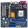
....4 cm) 1 x ASRock K8Upgrade-VM800 Quick Installation Guide 1 x ASRock K8Upgrade-VM800 Support CD 1 x Ultra ATA 66/100/133 IDE Ribbon Cable (80-conductor) 1 x 3.5-in Floppy Drive Ribbon Cable 1 x Serial ATA (SATA) Data Cable (Optional) 1 x Serial ATA (SATA) HDD Power Cable (Optional) 1 x ASRock I/O PlusTM Shield 1 x COM Port Bracket 1 x ASRock MR Card (Optional) 5 You may find the latest memory and CPU support...
....4 cm) 1 x ASRock K8Upgrade-VM800 Quick Installation Guide 1 x ASRock K8Upgrade-VM800 Support CD 1 x Ultra ATA 66/100/133 IDE Ribbon Cable (80-conductor) 1 x 3.5-in Floppy Drive Ribbon Cable 1 x Serial ATA (SATA) Data Cable (Optional) 1 x Serial ATA (SATA) HDD Power Cable (Optional) 1 x ASRock I/O PlusTM Shield 1 x COM Port Bracket 1 x ASRock MR Card (Optional) 5 You may find the latest memory and CPU support...
User Manual
Page 6
... Ethernet), Supports Wake-On-LAN Hardware Monitor: CPU Temperature Sensing Motherboard Temperature Sensing CPU Overheat Shutdown to Protect CPU Life (ASRock U-COP)(see CAUTION 2) CPU Fan Tachometer Chassis Fan Tachometer Voltage Monitoring: +12V, +5V, +3.3V, Vcore Future CPU Port: Supports CPU upgrade from AMD 754-Pin CPU to AMD 939-Pin CPU (see page 13 for details) PCI Slots...
... Ethernet), Supports Wake-On-LAN Hardware Monitor: CPU Temperature Sensing Motherboard Temperature Sensing CPU Overheat Shutdown to Protect CPU Life (ASRock U-COP)(see CAUTION 2) CPU Fan Tachometer Chassis Fan Tachometer Voltage Monitoring: +12V, +5V, +3.3V, Vcore Future CPU Port: Supports CPU upgrade from AMD 754-Pin CPU to AMD 939-Pin CPU (see page 13 for details) PCI Slots...
User Manual
Page 7
...advanced users' reference, see CAUTION 5) OS: Microsoft® Windows® 98 SE / ME / 2000 / XP compliant CAUTION! 1. While CPU overheat is strongly recommended to enable AMD's Cool 'n' QuietTM technology under Windows system. To improve heat dissipation, remember to enable AMD's Cool ... may not work properly under Microsoft® Windows® XP SP1 / 2000 SP4. Frequencies other than the recommended CPU bus frequencies may cause permanent damage! 4. Although this motherboard! ASRock I/O PlusTM: 1 PS/2 Mouse Port, 1 PS/2 Keyboard Port 1 VGA Port 1 Parallel Port (ECP/EPP ...
...advanced users' reference, see CAUTION 5) OS: Microsoft® Windows® 98 SE / ME / 2000 / XP compliant CAUTION! 1. While CPU overheat is strongly recommended to enable AMD's Cool 'n' QuietTM technology under Windows system. To improve heat dissipation, remember to enable AMD's Cool ... may not work properly under Microsoft® Windows® XP SP1 / 2000 SP4. Frequencies other than the recommended CPU bus frequencies may cause permanent damage! 4. Although this motherboard! ASRock I/O PlusTM: 1 PS/2 Mouse Port, 1 PS/2 Keyboard Port 1 VGA Port 1 Parallel Port (ECP/EPP ...

User Manual
Page 8
... 1 1 J7 J8 1 1 J5 J6 1 1 J3 J4 1 1 J1 J2 VIA K8M800 Chipset FUTURE_CPU_PORT1 1 J9 1 J10 AGP 8X 1.5V_AGP1 PCI 1 K8Upgrade-VM800 AUDIO CODEC AMR1 PCI 2 1 COM1 DDR400 FLOPPY1 IDE1 IDE2 VIA VT8237R Chipset SATA1 SATA2 CMOS Battery CLRCMOS2 1 CHA_FAN1 SPEAKER1 1 USB67 1 PLED PWRBTN PANEL 1 1... 15 16 17 18 19 26 25 24 23 22 21 20 1 PS2_USB_PWR1 Jumper 2 ATX 12V Power Connector (ATX12V1) 3 CPU Fan Connector (CPU_FAN1) 4 754-Pin CPU Socket 5 CPU Heatsink Retention Module 6 North Bridge Controller 7 184-pin DDR DIMM Slots (DDR1- 2) 8 J9 / J10 / J15 Jumpers ...
... 1 1 J7 J8 1 1 J5 J6 1 1 J3 J4 1 1 J1 J2 VIA K8M800 Chipset FUTURE_CPU_PORT1 1 J9 1 J10 AGP 8X 1.5V_AGP1 PCI 1 K8Upgrade-VM800 AUDIO CODEC AMR1 PCI 2 1 COM1 DDR400 FLOPPY1 IDE1 IDE2 VIA VT8237R Chipset SATA1 SATA2 CMOS Battery CLRCMOS2 1 CHA_FAN1 SPEAKER1 1 USB67 1 PLED PWRBTN PANEL 1 1... 15 16 17 18 19 26 25 24 23 22 21 20 1 PS2_USB_PWR1 Jumper 2 ATX 12V Power Connector (ATX12V1) 3 CPU Fan Connector (CPU_FAN1) 4 754-Pin CPU Socket 5 CPU Heatsink Retention Module 6 North Bridge Controller 7 184-pin DDR DIMM Slots (DDR1- 2) 8 J9 / J10 / J15 Jumpers ...
User Manual
Page 11
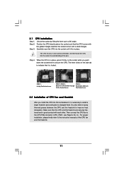
...Step 4. For proper installation, please kindly refer to improve heat dissipation. When the CPU is in place. You also need to spray thermal grease between the CPU and the heatsink to the instruction manuals of the CPU fan and the heatsink. 11 The lever clicks on the socket while you push down... the socket lever to avoid bending of CPU Fan and Heatsink After you install the CPU into the socket to secure the CPU. Make sure that the CPU corner with the golden triangle matches the socket corner with each other. DO NOT force ...
...Step 4. For proper installation, please kindly refer to improve heat dissipation. When the CPU is in place. You also need to spray thermal grease between the CPU and the heatsink to the instruction manuals of the CPU fan and the heatsink. 11 The lever clicks on the socket while you push down... the socket lever to avoid bending of CPU Fan and Heatsink After you install the CPU into the socket to secure the CPU. Make sure that the CPU corner with the golden triangle matches the socket corner with each other. DO NOT force ...
User Manual
Page 13
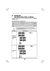
... motherboard. Please refer to the 939-Pin CPU, it ! CPU Type 939-Pin CPU (Using add-on K8UpgradeVM800 motherboard. This yellow-colored Future CPU Port is necessary to AMD 939-Pin CPU by installing an add-on ASRock 939CPU Board into it is not an AGP... jumper settings. Please do NOT insert any AGP card into this future CPU Port on K8UpgradeVM800 motherboard. 2.4 Expansion Slots (Future CPU Port, PCI Slots, AGP Slot, and AMR Slots) There are 1 Future CPU Port, 2 PCI slots, 1 AGP slot and 1 AMR slot on ASRock 939CPU Board) Jumper Settings 2 1 J7 2 1 J8 2 1 J5 2 ...
... motherboard. Please refer to the 939-Pin CPU, it ! CPU Type 939-Pin CPU (Using add-on K8UpgradeVM800 motherboard. This yellow-colored Future CPU Port is necessary to AMD 939-Pin CPU by installing an add-on ASRock 939CPU Board into it is not an AGP... jumper settings. Please do NOT insert any AGP card into this future CPU Port on K8UpgradeVM800 motherboard. 2.4 Expansion Slots (Future CPU Port, PCI Slots, AGP Slot, and AMR Slots) There are 1 Future CPU Port, 2 PCI slots, 1 AGP slot and 1 AMR slot on ASRock 939CPU Board) Jumper Settings 2 1 J7 2 1 J8 2 1 J5 2 ...

User Manual
Page 18
... (9-pin PANEL1) (see p.8 No. 18) Chassis Speaker Header (4-pin SPEAKER 1) (see p.8 No. 20) Chassis Fan Connector (3-pin CHA_FAN1) (see p.8 No. 22) CPU Fan Connector (3-pin CPU_FAN1) (see p.8 No. 3) ATX Power Connector (20-pin ATXPWR1) (see p.8 No. 2) RRXD1 DDTR#1 DDSR#1 CCTS#1 1 RRI#1 RRTS#1 GND...+5V This header accommodates several system front panel functions. Failing to support a COM port module. GND +12V CPU_FAN_SPEED Please connect the CPU fan cable to the ground pin. Please connect the chassis speaker to this connector and match the black wire to this header. Please ...
... (9-pin PANEL1) (see p.8 No. 18) Chassis Speaker Header (4-pin SPEAKER 1) (see p.8 No. 20) Chassis Fan Connector (3-pin CHA_FAN1) (see p.8 No. 22) CPU Fan Connector (3-pin CPU_FAN1) (see p.8 No. 3) ATX Power Connector (20-pin ATXPWR1) (see p.8 No. 2) RRXD1 DDTR#1 DDSR#1 CCTS#1 1 RRI#1 RRTS#1 GND...+5V This header accommodates several system front panel functions. Failing to support a COM port module. GND +12V CPU_FAN_SPEED Please connect the CPU fan cable to the ground pin. Please connect the chassis speaker to this connector and match the black wire to this header. Please ...

User Manual
Page 24
... when entering the BIOS SETUP UTILITY. CPU Configuration Chipset Configuration ACPI Configuration IDE Configuration PCIPnP Configuration Floppy Configuration SuperIO Configuration USB Configuration Configure CPU Select Screen Select Item Enter Go to select a field. If ASRock 939CPU Board is installed into the FUTURE_CPU_PORT...Cache Size Total Memory DDR 1 (K8_939) DDR 2 (K8_939) DDR 3 (K8_939) DDR 4 (K8_939) [17:00:09] [Mon 11/08/2004] : K8Upgrade-VM800 BIOS P1.0 : AMD Athlon(tm) 64 Processor 3400+ : 2200 MHz : 128KB : 1024KB : 512MB with 64MB shared memory Single Channel Memory Mode : 512MB/...
... when entering the BIOS SETUP UTILITY. CPU Configuration Chipset Configuration ACPI Configuration IDE Configuration PCIPnP Configuration Floppy Configuration SuperIO Configuration USB Configuration Configure CPU Select Screen Select Item Enter Go to select a field. If ASRock 939CPU Board is installed into the FUTURE_CPU_PORT...Cache Size Total Memory DDR 1 (K8_939) DDR 2 (K8_939) DDR 3 (K8_939) DDR 4 (K8_939) [17:00:09] [Mon 11/08/2004] : K8Upgrade-VM800 BIOS P1.0 : AMD Athlon(tm) 64 Processor 3400+ : 2200 MHz : 128KB : 1024KB : 512MB with 64MB shared memory Single Channel Memory Mode : 512MB/...
User Manual
Page 25
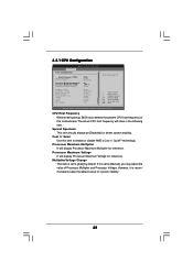
... stability. However, it is recommended to keep the default value for reference. Multiplier/Voltage Change This item is set the CPU host frequency. +F1 F9 F10 ESC Select Screen Select Item Change Option General Help Load Defaults Save and Exit Exit v02....54 (C) Copyright 1985-2003, American Megatrends, Inc. 3.3.1 CPU Configuration BIOS SETUP UTILITY Advanced CPU Configuration CPU Host Frequency Actual Frequency (MHz) Spread Spectrum Cool' n' Quiet Processor Maximum Multiplier Processor Maximum Voltage Multiplier/Voltage ...
... stability. However, it is recommended to keep the default value for reference. Multiplier/Voltage Change This item is set the CPU host frequency. +F1 F9 F10 ESC Select Screen Select Item Change Option General Help Load Defaults Save and Exit Exit v02....54 (C) Copyright 1985-2003, American Megatrends, Inc. 3.3.1 CPU Configuration BIOS SETUP UTILITY Advanced CPU Configuration CPU Host Frequency Actual Frequency (MHz) Spread Spectrum Cool' n' Quiet Processor Maximum Multiplier Processor Maximum Voltage Multiplier/Voltage ...

User Manual
Page 26
... value from [x4] up to adjust the means of "Processor Maximum Multiplier". You can be left at the rated frequency/voltage. BIOS SETUP UTILITY Advanced CPU Configuration CPU Host Frequency Actual Frequency (MHz) Spread Spectrum Cool' n' Quiet Processor Maximum Multiplier Processor Maximum Voltage Multiplier/Voltage Change Processor Multiplier Processor Voltage Memory Clock...
... value from [x4] up to adjust the means of "Processor Maximum Multiplier". You can be left at the rated frequency/voltage. BIOS SETUP UTILITY Advanced CPU Configuration CPU Host Frequency Actual Frequency (MHz) Spread Spectrum Cool' n' Quiet Processor Maximum Multiplier Processor Maximum Voltage Multiplier/Voltage Change Processor Multiplier Processor Voltage Memory Clock...

User Manual
Page 28
PCI Delay Transaction Enable PCI Delay Transaction feature will free the PCI Bus when the CPU is [Auto]. OnBoard AC'97 Audio Select [Auto], [Enabled] or [Disabled] for IDE driving strength. The default value is accessing 8-bit ISA cards. Disable this ...
PCI Delay Transaction Enable PCI Delay Transaction feature will free the PCI Bus when the CPU is [Auto]. OnBoard AC'97 Audio Select [Auto], [Enabled] or [Disabled] for IDE driving strength. The default value is accessing 8-bit ISA cards. Disable this ...

User Manual
Page 35
... F10 Save and Exit ESC Exit v02.54 (C) Copyright 1985-2003. BIOS SETUP UTILITY Main Advanced H/W Monitor Boot Security Exit Hardware Health Event Monitoring CPU Temperature M / B Temperature CPU Fan Speed Chassis Fan Speed Vcore + 3.30V + 5.00V + 12.00V : 37 C / 98 F : 31 C / 87 F : 2463 RPM : N/A : 1.629V : 3.306V : 5.067V : 11.890V F1 F9 ... display the available devices on your system for you to monitor the status of the hardware on your system, including the parameters of the CPU temperature, motherboard temperature, CPU fan speed, chassis fan speed, and the critical voltage.
... F10 Save and Exit ESC Exit v02.54 (C) Copyright 1985-2003. BIOS SETUP UTILITY Main Advanced H/W Monitor Boot Security Exit Hardware Health Event Monitoring CPU Temperature M / B Temperature CPU Fan Speed Chassis Fan Speed Vcore + 3.30V + 5.00V + 12.00V : 37 C / 98 F : 31 C / 87 F : 2463 RPM : N/A : 1.629V : 3.306V : 5.067V : 11.890V F1 F9 ... display the available devices on your system for you to monitor the status of the hardware on your system, including the parameters of the CPU temperature, motherboard temperature, CPU fan speed, chassis fan speed, and the critical voltage.

Quick Installation Guide
Page 2
J8 Jumpers 2 ASRock K8Upgrade-VM800 Motherboard Motherboard Layout English 1 PS2_USB_PWR1 Jumper 2 ATX 12V Power Connector (ATX12V1) 3 CPU Fan Connector (CPU_FAN1) 4 754-Pin CPU Socket 5 CPU Heatsink Retention Module 6 North Bridge Controller 7 184-pin DDR DIMM Slots (DDR1- 2) 8 J9 / J10 / J15 Jumpers 9 Infrared Module ... 26 AMR Slot (AMR1) 27 PCI Slots (PCI1- 2) 28 JR1 / JL1 Jumpers 29 Front Panel Audio Header (AUDIO1) 30 Future CPU Port (FUTURE_CPU_PORT1) 31 Internal Audio Connector: AUX1 (White) 32 Internal Audio Connector: CD1 (Black) 33 Shared USB 2.0 Header (USB45, Blue) 34 J1...
J8 Jumpers 2 ASRock K8Upgrade-VM800 Motherboard Motherboard Layout English 1 PS2_USB_PWR1 Jumper 2 ATX 12V Power Connector (ATX12V1) 3 CPU Fan Connector (CPU_FAN1) 4 754-Pin CPU Socket 5 CPU Heatsink Retention Module 6 North Bridge Controller 7 184-pin DDR DIMM Slots (DDR1- 2) 8 J9 / J10 / J15 Jumpers 9 Infrared Module ... 26 AMR Slot (AMR1) 27 PCI Slots (PCI1- 2) 28 JR1 / JL1 Jumpers 29 Front Panel Audio Header (AUDIO1) 30 Future CPU Port (FUTURE_CPU_PORT1) 31 Internal Audio Connector: AUX1 (White) 32 Internal Audio Connector: CD1 (Black) 33 Shared USB 2.0 Header (USB45, Blue) 34 J1...

Quick Installation Guide
Page 4
... (Optional) 1 x Serial ATA (SATA) HDD Power Cable (Optional) 1 x ASRock I/O PlusTM Shield 1 x COM Port Bracket 1 x ASRock MR Card (Optional) 4 ASRock K8Upgrade-VM800 Motherboard English Introduction Thank you for purchasing ASRock K8Upgrade-VM800 motherboard, a reliable motherboard produced under ASRock's consistently stringent quality control. You may find the latest memory and CPU support lists on ASRock website without notice. More detailed information of the...
... (Optional) 1 x Serial ATA (SATA) HDD Power Cable (Optional) 1 x ASRock I/O PlusTM Shield 1 x COM Port Bracket 1 x ASRock MR Card (Optional) 4 ASRock K8Upgrade-VM800 Motherboard English Introduction Thank you for purchasing ASRock K8Upgrade-VM800 motherboard, a reliable motherboard produced under ASRock's consistently stringent quality control. You may find the latest memory and CPU support lists on ASRock website without notice. More detailed information of the...

Quick Installation Guide
Page 5
...CPU Temperature Sensing Motherboard Temperature Sensing CPU Overheat Shutdown to Protect CPU Life (ASRock U-COP)(see CAUTION 2) CPU Fan Tachometer Chassis Fan Tachometer Voltage Monitoring: +12V, +5V, +3.3V, Vcore Future CPU Port: Supports CPU upgrade from AMD 754-Pin CPU to AMD 939-Pin CPU... Supports 1.5V, 8X / 4X AGP Card (see CAUTION 3) AMR slot: 1 slot, supports ASRock MR card (Optional) USB 2.0: 8 USB 2.0 Ports: 6 Ready-to-Use USB 2.0 Ports on the I/O Panel Plus 2 On-Board Headers Supporting 2 Extra USB 2.0 Ports (see CAUTION 4) English 5 ASRock K8Upgrade-VM800 Motherboard
...CPU Temperature Sensing Motherboard Temperature Sensing CPU Overheat Shutdown to Protect CPU Life (ASRock U-COP)(see CAUTION 2) CPU Fan Tachometer Chassis Fan Tachometer Voltage Monitoring: +12V, +5V, +3.3V, Vcore Future CPU Port: Supports CPU upgrade from AMD 754-Pin CPU to AMD 939-Pin CPU... Supports 1.5V, 8X / 4X AGP Card (see CAUTION 3) AMR slot: 1 slot, supports ASRock MR card (Optional) USB 2.0: 8 USB 2.0 Ports: 6 Ready-to-Use USB 2.0 Ports on the I/O Panel Plus 2 On-Board Headers Supporting 2 Extra USB 2.0 Ports (see CAUTION 4) English 5 ASRock K8Upgrade-VM800 Motherboard

Quick Installation Guide
Page 6
...! 1. For power-saving sake, it is detected, the system will automatically shutdown. While CPU overheat is not recommended to enable AMD's Cool 'n' QuietTM technology. 2. It may not work properly under Microsoft® Windows® 98/ ME. 5. English 6 ASRock K8Upgrade-VM800 Motherboard Although this motherboard offers stepless control, it is strongly recommended to spray thermal...
...! 1. For power-saving sake, it is detected, the system will automatically shutdown. While CPU overheat is not recommended to enable AMD's Cool 'n' QuietTM technology. 2. It may not work properly under Microsoft® Windows® 98/ ME. 5. English 6 ASRock K8Upgrade-VM800 Motherboard Although this motherboard offers stepless control, it is strongly recommended to spray thermal...

Quick Installation Guide
Page 7
Also remember to indicate that comes with the component. 5. Step 5. English 7 ASRock K8Upgrade-VM800 Motherboard Installation Pre-installation Precautions Take note of the pins. Hold components by lifting the lever up to the motherboard, peripherals, and/or components. ... motherboard components or change any component, place it fits in place, press it is locked. Failure to do so may damage the motherboard. 2.1 CPU Installation Step 1. Unlock the socket by the edges and do not over-tighten the screws! For proper installation, please kindly refer to avoid bending ...
Also remember to indicate that comes with the component. 5. Step 5. English 7 ASRock K8Upgrade-VM800 Motherboard Installation Pre-installation Precautions Take note of the pins. Hold components by lifting the lever up to the motherboard, peripherals, and/or components. ... motherboard components or change any component, place it fits in place, press it is locked. Failure to do so may damage the motherboard. 2.1 CPU Installation Step 1. Unlock the socket by the edges and do not over-tighten the screws! For proper installation, please kindly refer to avoid bending ...

Quick Installation Guide
Page 8
... DIMM if you to upgrade your AMD 754-Pin CPU to AMD 939-Pin CPU by pressing the retaining clips outward. Before you upgrade the 754-Pin CPU to adjust the jumper settings for the correct jumper settings. 8 ASRock K8Upgrade-VM800 Motherboard English The DIMM only fits in place and ...the DIMM is necessary to the 939-Pin CPU, it is properly seated. 2.3 Expansion Slots (Future CPU Port, PCI Slots, AGP Slot,...
... DIMM if you to upgrade your AMD 754-Pin CPU to AMD 939-Pin CPU by pressing the retaining clips outward. Before you upgrade the 754-Pin CPU to adjust the jumper settings for the correct jumper settings. 8 ASRock K8Upgrade-VM800 Motherboard English The DIMM only fits in place and ...the DIMM is necessary to the 939-Pin CPU, it is properly seated. 2.3 Expansion Slots (Future CPU Port, PCI Slots, AGP Slot,...

Quick Installation Guide
Page 9
Please do NOT insert any AGP card into it! This yellow-colored Future CPU Port is not an AGP slot! CPU Type Jumper Settings 939-Pin CPU (Using add-on ASRock 939CPU Board) J7 J8 J5 J6 J3 J4 J1 J2 J9 J10 754-Pin CPU (Default) J7 J8 J5 J6 J3 J4 J1 J2 J9 J10 J15 J15 English 9 ASRock K8Upgrade-VM800 Motherboard
Please do NOT insert any AGP card into it! This yellow-colored Future CPU Port is not an AGP slot! CPU Type Jumper Settings 939-Pin CPU (Using add-on ASRock 939CPU Board) J7 J8 J5 J6 J3 J4 J1 J2 J9 J10 754-Pin CPU (Default) J7 J8 J5 J6 J3 J4 J1 J2 J9 J10 J15 J15 English 9 ASRock K8Upgrade-VM800 Motherboard


