User Manual
Page 6
...Port: Supports up to 2 Floppy Disk Drives Audio: 5.1 channels AC'97 Audio OnBoard VGA: Intergrated UniChrome PRO 3D/2D Graphics Controller , supports DirectX 8.1 LAN: Speed: 802.3u (10/100 Ethernet), Supports Wake-On-LAN Hardware Monitor: CPU Temperature Sensing Motherboard Temperature Sensing CPU Overheat Shutdown to Protect CPU Life (ASRock U-COP)(see CAUTION 2) CPU Fan Tachometer Chassis Fan Tachometer Voltage Monitoring: +12V, +5V, +3.3V, Vcore Future CPU Port: Supports CPU upgrade from AMD 754-Pin CPU to AMD 939-Pin CPU (see page 13 for details) PCI Slots: 2 x PCI Slots...
...Port: Supports up to 2 Floppy Disk Drives Audio: 5.1 channels AC'97 Audio OnBoard VGA: Intergrated UniChrome PRO 3D/2D Graphics Controller , supports DirectX 8.1 LAN: Speed: 802.3u (10/100 Ethernet), Supports Wake-On-LAN Hardware Monitor: CPU Temperature Sensing Motherboard Temperature Sensing CPU Overheat Shutdown to Protect CPU Life (ASRock U-COP)(see CAUTION 2) CPU Fan Tachometer Chassis Fan Tachometer Voltage Monitoring: +12V, +5V, +3.3V, Vcore Future CPU Port: Supports CPU upgrade from AMD 754-Pin CPU to AMD 939-Pin CPU (see page 13 for details) PCI Slots: 2 x PCI Slots...

User Manual
Page 8
... 3 CPU Fan Connector (CPU_FAN1) 4 754-Pin CPU Socket 5 CPU Heatsink Retention Module 6 North Bridge Controller 7 184-pin DDR DIMM Slots (DDR1- 2) 8 J9 / J10 / J15 Jumpers 9 Infrared Module Header (IR1) 10 Flash Memory 11 ATX Power Connector (ATXPWR1) 12 Floppy Connector (FLOPPY1) 13 Primary IDE Connector (IDE1, Blue) 14 Secondary IDE Connector (IDE2, Black) 15 South Bridge Controller 16 Primary Serial ATA Connector (SATA1) 17 Secondary Serial ATA Connector (SATA2) 18 System Panel Header (PANEL1) 19 Game Port Header (GAME1) 20 Chassis Speaker Header (SPEAKER 1) 21 USB 2.0 Header...
... 3 CPU Fan Connector (CPU_FAN1) 4 754-Pin CPU Socket 5 CPU Heatsink Retention Module 6 North Bridge Controller 7 184-pin DDR DIMM Slots (DDR1- 2) 8 J9 / J10 / J15 Jumpers 9 Infrared Module Header (IR1) 10 Flash Memory 11 ATX Power Connector (ATXPWR1) 12 Floppy Connector (FLOPPY1) 13 Primary IDE Connector (IDE1, Blue) 14 Secondary IDE Connector (IDE2, Black) 15 South Bridge Controller 16 Primary Serial ATA Connector (SATA1) 17 Secondary Serial ATA Connector (SATA2) 18 System Panel Header (PANEL1) 19 Game Port Header (GAME1) 20 Chassis Speaker Header (SPEAKER 1) 21 USB 2.0 Header...
User Manual
Page 17
... SATA power cable to the power connector of SATA power cable to the power connector on the I /O PlusTM. When using the front panel USB ports by attaching the front panel USB cable to function. USB 2.0 Header (9-pin USB67) (see p.8 No. 33) 1 USB_PWR P-4 P+4 GND USB_PWR P-5 P+5 GND DUMMY This USB45 header is shared with the USB 2.0 ports 4,5 on ASRock I /O PlusTM accommodates 6 default USB 2.0 ports. O U T- These connectors allow you to support 2 additional USB 2.0 ports. R MIC-POWER MIC This is available to receive stereo audio input from sound...
... SATA power cable to the power connector of SATA power cable to the power connector on the I /O PlusTM. When using the front panel USB ports by attaching the front panel USB cable to function. USB 2.0 Header (9-pin USB67) (see p.8 No. 33) 1 USB_PWR P-4 P+4 GND USB_PWR P-5 P+5 GND DUMMY This USB45 header is shared with the USB 2.0 ports 4,5 on ASRock I /O PlusTM accommodates 6 default USB 2.0 ports. O U T- These connectors allow you to support 2 additional USB 2.0 ports. R MIC-POWER MIC This is available to receive stereo audio input from sound...
User Manual
Page 20
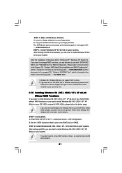
Insert the ASRock Support CD into the floppy drive. B. C. Then you need to check the installation guide in the Support CD for proper configuration. STEP 2: Use "SATA RAID BIOS" to set RAID configuration, you can start to format the floppy diskette and copy SATA drivers into the floppy drive, and press . Formatting the floppy diskette will lose ALL data in the folder at the beginning of system boot-up, press key, and then a window for boot devices selection...
Insert the ASRock Support CD into the floppy drive. B. C. Then you need to check the installation guide in the Support CD for proper configuration. STEP 2: Use "SATA RAID BIOS" to set RAID configuration, you can start to format the floppy diskette and copy SATA drivers into the floppy drive, and press . Formatting the floppy diskette will lose ALL data in the folder at the beginning of system boot-up, press key, and then a window for boot devices selection...
User Manual
Page 21
... to install Windows 98 / ME / 2000 / XP / XP 64-bit on your IDE HDDs instead of Windows 2000 / Windows XP / Windows XP 64-bit OS, if you want to set up RAID functions, there is located in the folder at the following path in Windows environment, please install SATA drivers from [RAID] to install Windows 98 / Windows ME on your floppy drive. If you want to [non-RAID]. B. Set the "SATA Operation Mode" option from the Support CD...
... to install Windows 98 / ME / 2000 / XP / XP 64-bit on your IDE HDDs instead of Windows 2000 / Windows XP / Windows XP 64-bit OS, if you want to set up RAID functions, there is located in the folder at the following path in Windows environment, please install SATA drivers from [RAID] to install Windows 98 / Windows ME on your floppy drive. If you want to [non-RAID]. B. Set the "SATA Operation Mode" option from the Support CD...
User Manual
Page 27
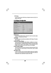
... memory size will switch the PCI Bus scanning order while searching for graphics memory. The default value is [Auto]. Primary Graphics Adapter This item will be [64MB]; It allows you to select the type of Primary VGA in case of the PCI memory address range used for video card. DRAM Voltage Use this field at the default value unless the installed AGP card's specifications requires other sizes. 27 When the total memory is [2T]. 3.3.2 Chipset Configuration Advanced Chipset Settings BIOS SETUP UTILITY To set to [Auto]. Configuration options...
... memory size will switch the PCI Bus scanning order while searching for graphics memory. The default value is [Auto]. Primary Graphics Adapter This item will be [64MB]; It allows you to select the type of Primary VGA in case of the PCI memory address range used for video card. DRAM Voltage Use this field at the default value unless the installed AGP card's specifications requires other sizes. 27 When the total memory is [2T]. 3.3.2 Chipset Configuration Advanced Chipset Settings BIOS SETUP UTILITY To set to [Auto]. Configuration options...
User Manual
Page 30
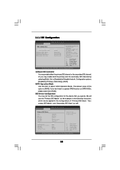
... Primary IDE Controller. BIOS SETUP UTILITY Advanced Primary IDE Master Device Vendor Size LBA Mode Block Mode PIO Mode Async DMA Ultra DMA S.M.A.R.T. Type LBA/Large Mode Block (Multi-Sector Transfer) PIO Mode DMA Mode S.M.A.R.T. 32Bit Data Transfer :Hard Disk :ST340014A :40.0 GB :Supported :16Sectors :4 :MultiWord DMA-2 :Ultra DMA-5 :Supported [Auto] [Auto] [Auto] [Auto] [Auto] [Disabled] [Disabled] Select the type of device connected to [Disabled] will use the "Primary IDE Master" as well. SECONDARY: enables only the Secondary IDE Controller. Or you may set the IDE configuration for...
... Primary IDE Controller. BIOS SETUP UTILITY Advanced Primary IDE Master Device Vendor Size LBA Mode Block Mode PIO Mode Async DMA Ultra DMA S.M.A.R.T. Type LBA/Large Mode Block (Multi-Sector Transfer) PIO Mode DMA Mode S.M.A.R.T. 32Bit Data Transfer :Hard Disk :ST340014A :40.0 GB :Supported :16Sectors :4 :MultiWord DMA-2 :Ultra DMA-5 :Supported [Auto] [Auto] [Auto] [Auto] [Auto] [Disabled] [Disabled] Select the type of device connected to [Disabled] will use the "Primary IDE Master" as well. SECONDARY: enables only the Secondary IDE Controller. Or you may set the IDE configuration for...
User Manual
Page 31
..., to partition and format the new IDE hard disk drives. Make sure to set the PIO mode to enhance hard disk performance by reading or writing more data during each transfer. Block (Multi-Sector Transfer) The default value of this item to enable or disable the S.M.A.R.T. (Self-Monitoring, Analysis, and Reporting Technology) feature. Configuration options: [Disabled], [Auto], [Enabled]. 32-Bit Data Transfer Use this feature is necessary so that you...
..., to partition and format the new IDE hard disk drives. Make sure to set the PIO mode to enhance hard disk performance by reading or writing more data during each transfer. Block (Multi-Sector Transfer) The default value of this item to enable or disable the S.M.A.R.T. (Self-Monitoring, Analysis, and Reporting Technology) feature. Configuration options: [Disabled], [Auto], [Enabled]. 32-Bit Data Transfer Use this feature is necessary so that you...
User Manual
Page 33
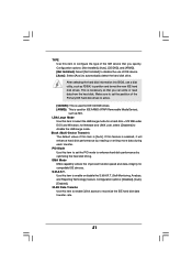
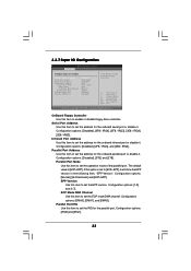
...IO Configuration BIOS SETUP UTILITY Advanced Configure Super IO Chipset OnBoard Floppy Controller Serial Port Address Infrared Port Address Parallel Port Address Parallel Port Mode EPP Version ECP Mode DMA Channel Parallel Port IRQ OnBoard Game Port OnBoard MIDI Port [Enabled] [3F8 / IRQ4] [Disabled] [378] [ECP + EPP] [1.9] [DMA3] [IRQ7] [Enabled] [Disabled] Allow BIOS to set the address for the onboard parallel port or disable it. Configuration options: [DMA0], [DMA1], and [DMA3]. Serial Port Address Use this item to set the ECP mode DMA channel. Parallel Port Address Use...
...IO Configuration BIOS SETUP UTILITY Advanced Configure Super IO Chipset OnBoard Floppy Controller Serial Port Address Infrared Port Address Parallel Port Address Parallel Port Mode EPP Version ECP Mode DMA Channel Parallel Port IRQ OnBoard Game Port OnBoard MIDI Port [Enabled] [3F8 / IRQ4] [Disabled] [378] [ECP + EPP] [1.9] [DMA3] [IRQ7] [Enabled] [Disabled] Allow BIOS to set the address for the onboard parallel port or disable it. Configuration options: [DMA0], [DMA1], and [DMA3]. Serial Port Address Use this item to set the ECP mode DMA channel. Parallel Port Address Use...
User Manual
Page 34
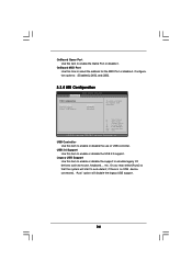
...so that the system will disable the legacy USB support. 34 USB Controller Use this itme to auto-detect; if there is no USB device connected, "Auto" option will start to select the address for the MIDI Port or disable it . Configuration options: [Disabled], [300], and [330]. 3.3.8 USB Configuration BIOS SETUP UTILITY Advanced USB Configuration USB Controller USB 2.0 Support Legacy USB Support [Enabled] [Enabled] [Disabled] To enable or disable the onboard USB controllers. +F1 F9 F10 ESC Select Screen Select Item Change Option General Help Load Defaults Save and Exit Exit v02...
...so that the system will disable the legacy USB support. 34 USB Controller Use this itme to auto-detect; if there is no USB device connected, "Auto" option will start to select the address for the MIDI Port or disable it . Configuration options: [Disabled], [300], and [330]. 3.3.8 USB Configuration BIOS SETUP UTILITY Advanced USB Configuration USB Controller USB 2.0 Support Legacy USB Support [Enabled] [Enabled] [Disabled] To enable or disable the onboard USB controllers. +F1 F9 F10 ESC Select Screen Select Item Change Option General Help Load Defaults Save and Exit Exit v02...
User Manual
Page 36
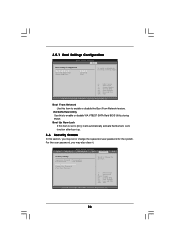
Boot From Network Use this to enable or disable VIA VT8237 SATA Raid BIOS Utility during POST. VIA SATA Raid Utility Use this item to [On], it . BIOS SETUP UTILITY Main Advanced H/W Monitor Boot Security Exit Security Settings Supervisor Password : Not Installed User Password : Not Installed Change Supervisor Password Change User Password Clear User Password Install or Change the password. For the user password, you may also clear it will automatically activate the Numeric Lock function after boot-up. 3.6 Security Screen In this item is set or change the supervisor/user ...
Boot From Network Use this to enable or disable VIA VT8237 SATA Raid BIOS Utility during POST. VIA SATA Raid Utility Use this item to [On], it . BIOS SETUP UTILITY Main Advanced H/W Monitor Boot Security Exit Security Settings Supervisor Password : Not Installed User Password : Not Installed Change Supervisor Password Change User Password Clear User Password Install or Change the password. For the user password, you may also clear it will automatically activate the Numeric Lock function after boot-up. 3.6 Security Screen In this item is set or change the supervisor/user ...
User Manual
Page 38
... ASRock Express GbL PCI Express LAN card driver if the system detects the installed devices. Please install the necessary drivers to your CD-ROM drive. The CD automatically displays the Main Menu if "AUTORUN" is enabled in this chapter for further information. 38 Software Support 4.1 Install Operating System This motherboard supports various Microsoft® Windows® operating systems: 98 SE / ME / 2000 / XP. If the Main Menu did not appear automatically, locate and double click on a specific...
... ASRock Express GbL PCI Express LAN card driver if the system detects the installed devices. Please install the necessary drivers to your CD-ROM drive. The CD automatically displays the Main Menu if "AUTORUN" is enabled in this chapter for further information. 38 Software Support 4.1 Install Operating System This motherboard supports various Microsoft® Windows® operating systems: 98 SE / ME / 2000 / XP. If the Main Menu did not appear automatically, locate and double click on a specific...

User Manual
Page 39
... Settings, then Control Panel. 2. button. 4. From the Windows 98SE/ME operating system, click the Start button. From the Energy saving features of monitor group, click the "Settings..." Click OK to enable AMD's Cool 'n' QuietTM technology under Windows system. From the Power Options Properties dialog box, select AMD's Cool 'n' QuietTM Technology tab. 5. When using Windows 98SE/ME operating system, please follow the instruction below to enable AMD's Cool 'n' QuietTM technology: 1. Switch to install "AMD Processor Driver" from the "Support CD...
... Settings, then Control Panel. 2. button. 4. From the Windows 98SE/ME operating system, click the Start button. From the Energy saving features of monitor group, click the "Settings..." Click OK to enable AMD's Cool 'n' QuietTM technology under Windows system. From the Power Options Properties dialog box, select AMD's Cool 'n' QuietTM Technology tab. 5. When using Windows 98SE/ME operating system, please follow the instruction below to enable AMD's Cool 'n' QuietTM technology: 1. Switch to install "AMD Processor Driver" from the "Support CD...

Quick Installation Guide
Page 2
...2 ASRock K8Upgrade-VM800 Motherboard Motherboard Layout English 1 PS2_USB_PWR1 Jumper 2 ATX 12V Power Connector (ATX12V1) 3 CPU Fan Connector (CPU_FAN1) 4 754-Pin CPU Socket 5 CPU Heatsink Retention Module 6 North Bridge Controller 7 184-pin DDR DIMM Slots (DDR1- 2) 8 J9 / J10 / J15 Jumpers 9 Infrared Module Header (IR1) 10 Flash Memory 11 ATX Power Connector (ATXPWR1) 12 Floppy Connector (FLOPPY1) 13 Primary IDE Connector (IDE1, Blue) 14 Secondary IDE Connector (IDE2, Black) 15 South Bridge Controller 16 Primary Serial ATA Connector (SATA1) 17 Secondary Serial ATA Connector...
...2 ASRock K8Upgrade-VM800 Motherboard Motherboard Layout English 1 PS2_USB_PWR1 Jumper 2 ATX 12V Power Connector (ATX12V1) 3 CPU Fan Connector (CPU_FAN1) 4 754-Pin CPU Socket 5 CPU Heatsink Retention Module 6 North Bridge Controller 7 184-pin DDR DIMM Slots (DDR1- 2) 8 J9 / J10 / J15 Jumpers 9 Infrared Module Header (IR1) 10 Flash Memory 11 ATX Power Connector (ATXPWR1) 12 Floppy Connector (FLOPPY1) 13 Primary IDE Connector (IDE1, Blue) 14 Secondary IDE Connector (IDE2, Black) 15 South Bridge Controller 16 Primary Serial ATA Connector (SATA1) 17 Secondary Serial ATA Connector...

Quick Installation Guide
Page 5
...Floppy Port: Supports up to 2 Floppy Disk Drives Audio: 5.1 channels AC'97 Audio OnBoard VGA: Intergrated UniChrome PRO 3D/2D Graphics Controller , supports DirectX 8.1 LAN: Speed: 802.3u (10/100 Ethernet), Supports Wake-On-LAN Hardware Monitor: CPU Temperature Sensing Motherboard Temperature Sensing CPU Overheat Shutdown to Protect CPU Life (ASRock U-COP)(see CAUTION 2) CPU Fan Tachometer Chassis Fan Tachometer Voltage Monitoring: +12V, +5V, +3.3V, Vcore Future CPU Port: Supports CPU upgrade from AMD 754-Pin CPU to AMD 939-Pin CPU (see page 8 for details) PCI Slots: 2 x PCI...
...Floppy Port: Supports up to 2 Floppy Disk Drives Audio: 5.1 channels AC'97 Audio OnBoard VGA: Intergrated UniChrome PRO 3D/2D Graphics Controller , supports DirectX 8.1 LAN: Speed: 802.3u (10/100 Ethernet), Supports Wake-On-LAN Hardware Monitor: CPU Temperature Sensing Motherboard Temperature Sensing CPU Overheat Shutdown to Protect CPU Life (ASRock U-COP)(see CAUTION 2) CPU Fan Tachometer Chassis Fan Tachometer Voltage Monitoring: +12V, +5V, +3.3V, Vcore Future CPU Port: Supports CPU upgrade from AMD 754-Pin CPU to AMD 939-Pin CPU (see page 8 for details) PCI Slots: 2 x PCI...

Quick Installation Guide
Page 6
...! 1. English 6 ASRock K8Upgrade-VM800 Motherboard For power-saving sake, it is not recommended to perform over-clocking. See APPENDIX on the AGP slot of the system or damage the CPU. ASRock I/O PlusTM: 1 PS/2 Mouse Port, 1 PS/2 Keyboard Port 1 VGA Port 1 Parallel Port (ECP/EPP Support) 6 Ready-to-Use USB 2.0 Ports 1 RJ-45 Port Audio Jack: Line In / Line Out / Microphone COM Port: 1 COM Port Header to support a COM port module BIOS: AMI Legal BIOS Supports "Plug and Play" ACPI 2.0 Compliance Wake Up...
...! 1. English 6 ASRock K8Upgrade-VM800 Motherboard For power-saving sake, it is not recommended to perform over-clocking. See APPENDIX on the AGP slot of the system or damage the CPU. ASRock I/O PlusTM: 1 PS/2 Mouse Port, 1 PS/2 Keyboard Port 1 VGA Port 1 Parallel Port (ECP/EPP Support) 6 Ready-to-Use USB 2.0 Ports 1 RJ-45 Port Audio Jack: Line In / Line Out / Microphone COM Port: 1 COM Port Header to support a COM port module BIOS: AMI Legal BIOS Supports "Plug and Play" ACPI 2.0 Compliance Wake Up...

Quick Installation Guide
Page 13
... using the front panel USB ports by attaching the front panel USB cable to the power connector on ASRock I /O PlusTM. English 13 ASRock K8Upgrade-VM800 Motherboard Then connect the white end of SATA power cable to the power connector of SATA power cable to this USB 2.0 header is an interface for front panel audio cable that allows convenient connection and control of audio devices. If the rear USB ports are not sufficient, this header (USB45), the USB ports 4,5 on each drive. Front Panel Audio Header (9-pin AUDIO1) (see p.2, No. 9) This header supports an optional wireless...
... using the front panel USB ports by attaching the front panel USB cable to the power connector on ASRock I /O PlusTM. English 13 ASRock K8Upgrade-VM800 Motherboard Then connect the white end of SATA power cable to the power connector of SATA power cable to this USB 2.0 header is an interface for front panel audio cable that allows convenient connection and control of audio devices. If the rear USB ports are not sufficient, this header (USB45), the USB ports 4,5 on each drive. Front Panel Audio Header (9-pin AUDIO1) (see p.2, No. 9) This header supports an optional wireless...

Quick Installation Guide
Page 16
... ASRock K8Upgrade-VM800 Motherboard English Please insert a floppy diskette into the floppy diskette. During POST at the following path: .. \ SATA RAID BIOS STEP 3: Install Windows 2000 / Windows XP OS on your system. Formatting the floppy diskette will lose ALL data in the Support CD for boot devices selection appears. E. After making a SATA driver diskette and using "SATA RAID BIOS" to SATA Hard Disks Installation and RAID Configuration", which is located in the folder at the beginning of system boot-up, press key...
... ASRock K8Upgrade-VM800 Motherboard English Please insert a floppy diskette into the floppy diskette. During POST at the following path: .. \ SATA RAID BIOS STEP 3: Install Windows 2000 / Windows XP OS on your system. Formatting the floppy diskette will lose ALL data in the Support CD for boot devices selection appears. E. After making a SATA driver diskette and using "SATA RAID BIOS" to SATA Hard Disks Installation and RAID Configuration", which is located in the folder at the beginning of system boot-up, press key...

Quick Installation Guide
Page 17
... 64-bit With RAID Functions If you want to manage RAID functions, you are located at the following path in Windows environment, please install SATA drivers from the Support CD again so that "VIA RAID Tool" will be installed to your system as well. 17 ASRock K8Upgrade-VM800 Motherboard English B. A. Insert the floppy diskette into your floppy drive. Please refer to the document in the Support CD, "Guide to SATA Hard Disks Installation and RAID Configuration...
... 64-bit With RAID Functions If you want to manage RAID functions, you are located at the following path in Windows environment, please install SATA drivers from the Support CD again so that "VIA RAID Tool" will be installed to your system as well. 17 ASRock K8Upgrade-VM800 Motherboard English B. A. Insert the floppy diskette into your floppy drive. Please refer to the document in the Support CD, "Guide to SATA Hard Disks Installation and RAID Configuration...
Quick Installation Guide
Page 19
... Power-On-Self-Test (POST) to the User Manual (PDF file) contained in the Support CD. 4. otherwise, POST continues with the motherboard contains necessary drivers and useful utilities that will display the Main Menu automatically if "AUTORUN" is enabled in the Support CD to select among the predetermined choices. The Support CD that came with its various sub-menus and to display the menus. 19 ASRock K8Upgrade-VM800 Motherboard English To begin using the Support...
... Power-On-Self-Test (POST) to the User Manual (PDF file) contained in the Support CD. 4. otherwise, POST continues with the motherboard contains necessary drivers and useful utilities that will display the Main Menu automatically if "AUTORUN" is enabled in the Support CD to select among the predetermined choices. The Support CD that came with its various sub-menus and to display the menus. 19 ASRock K8Upgrade-VM800 Motherboard English To begin using the Support...


