
User Manual
Page 3
...Installation of Memory Modules (DIMM 14 2.4 Expansion Slots (PCI Slots and AGP Slot 15 2.5 Jumpers Setup 16 2.6 Onboard Headers and Connectors 17 2.7 Serial ATA (SATA) Hard Disks Installation 21 2.8 Hot Plug and Hot Swap Functions for Windows® VistaTM Premium 2007 and Basic Logo 9 1.4 Motherboard Layout 10 1.5 ASRock 8CH I/O 11 2 . BIOS SETUP UTILITY 25 3.1 Introduction 25 3.1.1 BIOS Menu Bar 25 3.1.2 Navigation Keys 26 3.2 Main Screen 26 3.3 Advanced Screen 27 3.3.1 CPU Configuration 28 3.3.2 Chipset Configuration 30 3.3.3 ACPI Configuration 32 3.3.4 IDE Configuration...
...Installation of Memory Modules (DIMM 14 2.4 Expansion Slots (PCI Slots and AGP Slot 15 2.5 Jumpers Setup 16 2.6 Onboard Headers and Connectors 17 2.7 Serial ATA (SATA) Hard Disks Installation 21 2.8 Hot Plug and Hot Swap Functions for Windows® VistaTM Premium 2007 and Basic Logo 9 1.4 Motherboard Layout 10 1.5 ASRock 8CH I/O 11 2 . BIOS SETUP UTILITY 25 3.1 Introduction 25 3.1.1 BIOS Menu Bar 25 3.1.2 Navigation Keys 26 3.2 Main Screen 26 3.3 Advanced Screen 27 3.3.1 CPU Configuration 28 3.3.2 Chipset Configuration 30 3.3.3 ACPI Configuration 32 3.3.4 IDE Configuration...
User Manual
Page 8
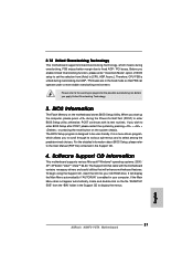
... proper connection. 6. Please visit our website for USB 2.0 works fine under Microsoft® Windows® VistaTM 64-bit / VistaTM / XP 64-bit / XP SP1 or SP2 / 2000 SP4. 7. This motherboard supports Untied Overclocking Technology. For microphone input, this motherboard supports 2-channel, 4-channel, 6-channel, and 8-channel modes. ASRock website http://www.asrock.com 8 Frequencies other than the recommended CPU bus frequencies may cause permanent damage! 5. For audio output, this motherboard supports both stereo and mono modes. As long as...
... proper connection. 6. Please visit our website for USB 2.0 works fine under Microsoft® Windows® VistaTM 64-bit / VistaTM / XP 64-bit / XP SP1 or SP2 / 2000 SP4. 7. This motherboard supports Untied Overclocking Technology. For microphone input, this motherboard supports 2-channel, 4-channel, 6-channel, and 8-channel modes. ASRock website http://www.asrock.com 8 Frequencies other than the recommended CPU bus frequencies may cause permanent damage! 5. For audio output, this motherboard supports both stereo and mono modes. As long as...
User Manual
Page 21
... driver page. STEP 4: Connect the other end of the SATA data cable to insert and remove the SATA HDDs while the system is called "Hot Swap" for internal storage devices. Therefore, the drivers you install can be auto-detected and listed on and in working condition. 2.9 Driver Installation Guide To install the drivers to your optical drive first. For users who install Windows® XP 64-bit OS and plan to install drivers to the SATA hard disk. STEP 2: Connect the SATA power cable...
... driver page. STEP 4: Connect the other end of the SATA data cable to insert and remove the SATA HDDs while the system is called "Hot Swap" for internal storage devices. Therefore, the drivers you install can be auto-detected and listed on and in working condition. 2.9 Driver Installation Guide To install the drivers to your optical drive first. For users who install Windows® XP 64-bit OS and plan to install drivers to the SATA hard disk. STEP 2: Connect the SATA power cable...

User Manual
Page 23
...; RAID driver. NOTE. Enter BIOS SETUP UTILITY Advanced screen IDE Configuration. A. STEP 3: Use "RAID Installation Guide" to install Windows® 2000 / Windows® XP / Windows® XP 64-bit OS on your system. After step1, 2, 3, you will see the message on SATA HDDs, you see these messages, Please insert a blank formatted diskette into floppy drive A: press any key to format the floppy diskette and copy SATA drivers into the floppy drive, and press any key. Then you can start to configure...
...; RAID driver. NOTE. Enter BIOS SETUP UTILITY Advanced screen IDE Configuration. A. STEP 3: Use "RAID Installation Guide" to install Windows® 2000 / Windows® XP / Windows® XP 64-bit OS on your system. After step1, 2, 3, you will see the message on SATA HDDs, you see these messages, Please insert a blank formatted diskette into floppy drive A: press any key to format the floppy diskette and copy SATA drivers into the floppy drive, and press any key. Then you can start to configure...

User Manual
Page 30
... access contention. 3.3.2 Chipset Configuration BIOS SETUP UTILITY Advanced Chipset Settings OnBoard UAA Audio OnBoard LAN [Auto] [Enabled] AGP Data Rate AGP Aperture Size AGP Fast Write AGP SideBand Address Primary Graphics Adapter [8X] [64MB] [Disabled] [Enabled] [PCI] CPU-NB Link Speed CPU-NB Kink Width DRAM Voltage AGP Voltage [Auto] [Auto] [Auto] [Auto] To set to adjust the AGP Data Rate. OnBoard LAN This allows you select [Auto], the onboard UAA Audio will be set DRAM Voltage. +F1 F9 F10 ESC Select Screen Select Item Change Option General Help Load Defaults Save...
... access contention. 3.3.2 Chipset Configuration BIOS SETUP UTILITY Advanced Chipset Settings OnBoard UAA Audio OnBoard LAN [Auto] [Enabled] AGP Data Rate AGP Aperture Size AGP Fast Write AGP SideBand Address Primary Graphics Adapter [8X] [64MB] [Disabled] [Enabled] [PCI] CPU-NB Link Speed CPU-NB Kink Width DRAM Voltage AGP Voltage [Auto] [Auto] [Auto] [Auto] To set to adjust the AGP Data Rate. OnBoard LAN This allows you select [Auto], the onboard UAA Audio will be set DRAM Voltage. +F1 F9 F10 ESC Select Screen Select Item Change Option General Help Load Defaults Save...
User Manual
Page 33
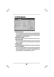
... IDE channel or the secondary IDE channel. BOTH: enables both the primary and the secondary IDE channels by selecting [Both]. Configuration options: [Disabled], [Primary], [Secondary], [Both]. OnBoard SATA Controller Use this item to enable or disable the "OnBoard SATA Controller" feature. 3.3.4 IDE Configuration Advanced BIOS SETUP UTILITY IDE Configuration OnBoard IDE Controller OnBoard SATA Controller SATA Operation Mode HDD Fast Detection Primary IDE Master Primary IDE Slave Secondary IDE Master Secondary IDE Slave SATA1 SATA2 [Both] [Enabled] [non-RAID] [Disabled] [Hard Disk...
... IDE channel or the secondary IDE channel. BOTH: enables both the primary and the secondary IDE channels by selecting [Both]. Configuration options: [Disabled], [Primary], [Secondary], [Both]. OnBoard SATA Controller Use this item to enable or disable the "OnBoard SATA Controller" feature. 3.3.4 IDE Configuration Advanced BIOS SETUP UTILITY IDE Configuration OnBoard IDE Controller OnBoard SATA Controller SATA Operation Mode HDD Fast Detection Primary IDE Master Primary IDE Slave Secondary IDE Master Secondary IDE Slave SATA1 SATA2 [Both] [Enabled] [non-RAID] [Disabled] [Hard Disk...

User Manual
Page 35
...-bit access to enable or disable the PCI IDE BusMaster feature. 35 PCI IDE BusMaster Use this item to maximize the IDE hard disk data transfer rate. 3.3.5 PCIPnP Configuration BIOS SETUP UTILITY Advanced Advanced PCI / PnP Settings PCI Latency Timer PCI IDE BusMaster [32] [Enabled] Value in this item to malfunction. It is 32. Setting wrong values in units of PCI clocks for PCI device latency timer register. +F1 F9 F10 ESC Select Screen Select Item Change Option General Help Load Defaults...
...-bit access to enable or disable the PCI IDE BusMaster feature. 35 PCI IDE BusMaster Use this item to maximize the IDE hard disk data transfer rate. 3.3.5 PCIPnP Configuration BIOS SETUP UTILITY Advanced Advanced PCI / PnP Settings PCI Latency Timer PCI IDE BusMaster [32] [Enabled] Value in this item to malfunction. It is 32. Setting wrong values in units of PCI clocks for PCI device latency timer register. +F1 F9 F10 ESC Select Screen Select Item Change Option General Help Load Defaults...

User Manual
Page 36
...]. 36 OnBoard Floppy Controller Use this item to enable or disable floppy drive controller. 3.3.6 Floppy Configuration In this section, you may configure the type of floppy drive connected to the system. +F1 F9 F10 ESC Select Screen Select Item Change Option General Help Load Defaults Save and Exit Exit v02.54 (C) Copyright 1985-2003, American Megatrends, Inc. 3.3.7 Super IO Configuration BIOS SETUP UTILITY Advanced Configure Super IO Chipset OnBoard Floppy Controller Serial Port Address Infrared Port Address Parallel Port Address Parallel Port Mode EPP Version ECP Mode DMA Channel...
...]. 36 OnBoard Floppy Controller Use this item to enable or disable floppy drive controller. 3.3.6 Floppy Configuration In this section, you may configure the type of floppy drive connected to the system. +F1 F9 F10 ESC Select Screen Select Item Change Option General Help Load Defaults Save and Exit Exit v02.54 (C) Copyright 1985-2003, American Megatrends, Inc. 3.3.7 Super IO Configuration BIOS SETUP UTILITY Advanced Configure Super IO Chipset OnBoard Floppy Controller Serial Port Address Infrared Port Address Parallel Port Address Parallel Port Mode EPP Version ECP Mode DMA Channel...
User Manual
Page 43
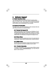
... the installed devices. Software Support 4.1 Install Operating System This motherboard supports various Microsoft® Windows® operating systems: 2000 / XP / XP 64-bit / VistaTM / VistaTM 64-bit. Click on the file "ASSETUP.EXE" from the BIN folder in the Support CD to your OS documentation for further information. 43 Because motherboard settings and hardware options vary, use the setup procedures in your CD-ROM drive. Please install the necessary drivers to install...
... the installed devices. Software Support 4.1 Install Operating System This motherboard supports various Microsoft® Windows® operating systems: 2000 / XP / XP 64-bit / VistaTM / VistaTM 64-bit. Click on the file "ASSETUP.EXE" from the BIN folder in the Support CD to your OS documentation for further information. 43 Because motherboard settings and hardware options vary, use the setup procedures in your CD-ROM drive. Please install the necessary drivers to install...
Quick Installation Guide
Page 2
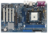
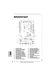
Motherboard Layout English 1 PS2_USB_PW1 Jumper 2 ATX 12V Power Connector (ATX12V1) 3 ATX Power Connector (ATXPWR1) 4 754-Pin CPU Socket 5 CPU Heatsink Retention Module 6 CPU Fan Connector (CPU_FAN1) 7 184-pin DDR DIMM Slots (DDR1- 2) 8 Secondary IDE Connector (IDE2, Black) 9 Primary IDE Connector (IDE1, Blue) 10 Primary Serial ATA Connector (SATA1) 11 Secondary Serial ATA Connector (SATA2) 12 AGP Slot (1.5V_AGP1) 13 NVIDIA Single Chipset 14 Clear CMOS Jumper (CLRCMOS2) 15 System Panel Header (PANEL1) 16 Chassis Speaker Header (SPEAKER 1) 17 USB 2.0 Header (USB4_5, Blue) 18 Chassis Fan ...
Motherboard Layout English 1 PS2_USB_PW1 Jumper 2 ATX 12V Power Connector (ATX12V1) 3 ATX Power Connector (ATXPWR1) 4 754-Pin CPU Socket 5 CPU Heatsink Retention Module 6 CPU Fan Connector (CPU_FAN1) 7 184-pin DDR DIMM Slots (DDR1- 2) 8 Secondary IDE Connector (IDE2, Black) 9 Primary IDE Connector (IDE1, Blue) 10 Primary Serial ATA Connector (SATA1) 11 Secondary Serial ATA Connector (SATA2) 12 AGP Slot (1.5V_AGP1) 13 NVIDIA Single Chipset 14 Clear CMOS Jumper (CLRCMOS2) 15 System Panel Header (PANEL1) 16 Chassis Speaker Header (SPEAKER 1) 17 USB 2.0 Header (USB4_5, Blue) 18 Chassis Fan ...
Quick Installation Guide
Page 5
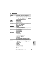
... Connector - CD in header 5 ASRock K8NF3-VSTA Motherboard English Socket 754 for AMD AthlonTM 64 and Sempron processors - Supports Untied Overclocking Technology (see CAUTION 2) - Max. FSB 800 MHz - CPU Frequency Stepless Control (see CAUTION 1) - Boot Failure Guard (B.F.G.) - 4 x PCI slots - 1 x AGP 8X slot (see CAUTION 3) - 1.2 Specifications Platform CPU Chipset Memory Hybrid Booster Expansion Slot Audio LAN Rear Panel I /O - 1 x PS/2 Mouse Port - 1 x PS/2 Keyboard Port - 1 x Serial Port: COM1 - 1 x Parallel Port (ECP/EPP Support) - 4 x Ready-to-Use USB 2.0 Ports...
... Connector - CD in header 5 ASRock K8NF3-VSTA Motherboard English Socket 754 for AMD AthlonTM 64 and Sempron processors - Supports Untied Overclocking Technology (see CAUTION 2) - Max. FSB 800 MHz - CPU Frequency Stepless Control (see CAUTION 1) - Boot Failure Guard (B.F.G.) - 4 x PCI slots - 1 x AGP 8X slot (see CAUTION 3) - 1.2 Specifications Platform CPU Chipset Memory Hybrid Booster Expansion Slot Audio LAN Rear Panel I /O - 1 x PS/2 Mouse Port - 1 x PS/2 Keyboard Port - 1 x Serial Port: COM1 - 1 x Parallel Port (ECP/EPP Support) - 4 x Ready-to-Use USB 2.0 Ports...
Quick Installation Guide
Page 7
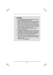
... motherboard supports 2-channel, 4-channel, 6-channel, and 8-channel modes. Microsoft® Windows® VistaTM / VistaTM 64-bit driver keeps on the AGP slot of the system or damage the CPU. 3. Please visit our website for proper connection. 6. CAUTION! 1. This motherboard supports Untied Overclocking Technology. Before you install the PC system. 4. As long as we have the latest driver, we will automatically shutdown. Although this motherboard! For audio output, this motherboard supports both stereo and mono modes. Frequencies...
... motherboard supports 2-channel, 4-channel, 6-channel, and 8-channel modes. Microsoft® Windows® VistaTM / VistaTM 64-bit driver keeps on the AGP slot of the system or damage the CPU. 3. Please visit our website for proper connection. 6. CAUTION! 1. This motherboard supports Untied Overclocking Technology. Before you install the PC system. 4. As long as we have the latest driver, we will automatically shutdown. Although this motherboard! For audio output, this motherboard supports both stereo and mono modes. Frequencies...
Quick Installation Guide
Page 15
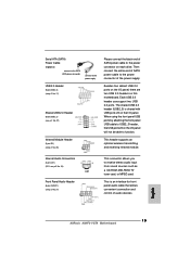
...When using the front panel USB ports by attaching the front panel USB cable to USB2_3 header, the USB ports 23 on the I /O panel, there are two USB 2.0 headers on each drive. Internal Audio Connectors (4-pin CD1) (CD1: see p.2 No. 24) Front Panel Audio Header (8-pin AUDIO1) (see p.2 No. 26) Please connect the black end of the power supply. This header supports an optional wireless transmitting and receiving infrared module. English 15 ASRock K8NF3-VSTA Motherboard Serial ATA (SATA) Power Cable (Optional) connect to the SATA HDD power connector connect to the power supply USB...
...When using the front panel USB ports by attaching the front panel USB cable to USB2_3 header, the USB ports 23 on the I /O panel, there are two USB 2.0 headers on each drive. Internal Audio Connectors (4-pin CD1) (CD1: see p.2 No. 24) Front Panel Audio Header (8-pin AUDIO1) (see p.2 No. 26) Please connect the black end of the power supply. This header supports an optional wireless transmitting and receiving infrared module. English 15 ASRock K8NF3-VSTA Motherboard Serial ATA (SATA) Power Cable (Optional) connect to the SATA HDD power connector connect to the power supply USB...
Quick Installation Guide
Page 18
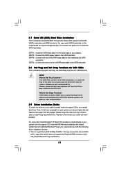
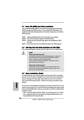
... supports Serial ATA (SATA) hard disks and RAID functions. "All in 1 Logo Driver( W/O HotPlug & RAID)": You may install SATA hard disks on the support CD driver page. NOTE What is Hot Swap Function? For users who install Windows® XP 64-bit OS and plan to install drivers to the SATA hard disk. 2.8 Hot Plug and Hot Swap Functions for SATA HDDs This motherboard supports Hot Plug and Hot Swap functions for internal storage devices. STEP 1: Install the SATA hard disks into the SATA HDD. If SATA HDDs are NOT set...
... supports Serial ATA (SATA) hard disks and RAID functions. "All in 1 Logo Driver( W/O HotPlug & RAID)": You may install SATA hard disks on the support CD driver page. NOTE What is Hot Swap Function? For users who install Windows® XP 64-bit OS and plan to install drivers to the SATA hard disk. 2.8 Hot Plug and Hot Swap Functions for SATA HDDs This motherboard supports Hot Plug and Hot Swap functions for internal storage devices. STEP 1: Install the SATA hard disks into the SATA HDD. If SATA HDDs are NOT set...
Quick Installation Guide
Page 19
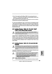
... system. 19 ASRock K8NF3-VSTA Motherboard A. RAID function is no need for the updates of making a SP4 disk: http://www.microsoft.com/Windows2000/downloads/servicepacks/sp4/ spdeploy.htm#the_integrated_installation_fmay STEP 1: Make a SATA Driver Diskette. Please visit our website for you want to change . Insert the ASRock Support CD into your optical drive to install Windows® 2000, Windows® XP or Windows® XP 64-bit on updating now. Please...
... system. 19 ASRock K8NF3-VSTA Motherboard A. RAID function is no need for the updates of making a SP4 disk: http://www.microsoft.com/Windows2000/downloads/servicepacks/sp4/ spdeploy.htm#the_integrated_installation_fmay STEP 1: Make a SATA Driver Diskette. Please visit our website for you want to change . Insert the ASRock Support CD into your optical drive to install Windows® 2000, Windows® XP or Windows® XP 64-bit on updating now. Please...
Quick Installation Guide
Page 20
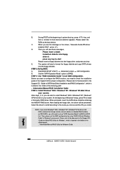
...floppy drive A: press any key. B. Enter BIOS SETUP UTILITY Advanced screen IDE Configuration. After reading the floppy disk, the driver will start to install Windows® 2000 / Windows® XP / Windows® XP 64-bit OS on your system. At the beginning of system boot-up "SATA Operation Mode" to set the RAID configuration by using "RAID Utility for Windows Guide English 20 ASRock K8NF3-VSTA Motherboard B. A. E. Then, please set up , press key, and then a window for proper configuration. NOTE. When you need to [RAID] in Windows...
...floppy drive A: press any key. B. Enter BIOS SETUP UTILITY Advanced screen IDE Configuration. After reading the floppy disk, the driver will start to install Windows® 2000 / Windows® XP / Windows® XP 64-bit OS on your system. At the beginning of system boot-up "SATA Operation Mode" to set the RAID configuration by using "RAID Utility for Windows Guide English 20 ASRock K8NF3-VSTA Motherboard B. A. E. Then, please set up , press key, and then a window for proper configuration. NOTE. When you need to [RAID] in Windows...
Quick Installation Guide
Page 21
... BIOS Setup, please refer to be user-friendly. Before you start up the computer, please press during overclocking, FSB enjoys better margin due to enter BIOS Setup utility; Therefore, CPU FSB is designed to the User Manual (PDF file) contained in the Support CD to display the menus. 21 ASRock K8NF3-VSTA Motherboard English Software Support CD information This motherboard supports various Microsoft® Windows® operating systems: 2000 / XP / XP 64-bit / VistaTM / VistaTM 64-bit...
... BIOS Setup, please refer to be user-friendly. Before you start up the computer, please press during overclocking, FSB enjoys better margin due to enter BIOS Setup utility; Therefore, CPU FSB is designed to the User Manual (PDF file) contained in the Support CD to display the menus. 21 ASRock K8NF3-VSTA Motherboard English Software Support CD information This motherboard supports various Microsoft® Windows® operating systems: 2000 / XP / XP 64-bit / VistaTM / VistaTM 64-bit...

RAID Installation Guide
Page 8
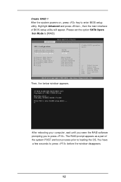
... a few seconds to enter BIOS setup utility. 2.3.2 Create Disk Array Create RAID 0 After the system powers on, press key to press before the window disappears. 8 Advanced BIOS SETUP UTILITY IDE Configuration OnBoard IDE Controller OnBoard SATA Controller SATA Operation Mode Primary IDE Master Primary IDE Slave Secondary IDE Master Secondary IDE Slave SATA1 SATA2 [Both] [Enabled] [RAID] [Hard Disk] [Not Detected] [ATAPI CDROM] [Not Detected] [Not Detected] [Not Detected] Config SATA operation mode. +F1 F10 ESC Select Screen Select Item Change Option General Help Save and...
... a few seconds to enter BIOS setup utility. 2.3.2 Create Disk Array Create RAID 0 After the system powers on, press key to press before the window disappears. 8 Advanced BIOS SETUP UTILITY IDE Configuration OnBoard IDE Controller OnBoard SATA Controller SATA Operation Mode Primary IDE Master Primary IDE Slave Secondary IDE Master Secondary IDE Slave SATA1 SATA2 [Both] [Enabled] [RAID] [Hard Disk] [Not Detected] [ATAPI CDROM] [Not Detected] [Not Detected] [Not Detected] Config SATA operation mode. +F1 F10 ESC Select Screen Select Item Change Option General Help Save and...
RAID Installation Guide
Page 12
... appears as a part of BIOS setup utility will appear. After rebooting your computer, wait until you seee the RAID software prompting you to loading the OS. Create RAID 1 After the system powers on, press key to [RAID]. Please set the option SATA Opera tion Mode to enter BIOS setup utility. Then, the below window appears. Advanced BIOS SETUP UTILITY IDE Configuration OnBoard IDE Controller OnBoard SATA Controller SATA Operation Mode Primary IDE Master Primary IDE Slave Secondary IDE Master Secondary IDE Slave SATA1 SATA2 [Both] [Enabled] [RAID] [Hard Disk] [Not Detected...
... appears as a part of BIOS setup utility will appear. After rebooting your computer, wait until you seee the RAID software prompting you to loading the OS. Create RAID 1 After the system powers on, press key to [RAID]. Please set the option SATA Opera tion Mode to enter BIOS setup utility. Then, the below window appears. Advanced BIOS SETUP UTILITY IDE Configuration OnBoard IDE Controller OnBoard SATA Controller SATA Operation Mode Primary IDE Master Primary IDE Slave Secondary IDE Master Secondary IDE Slave SATA1 SATA2 [Both] [Enabled] [RAID] [Hard Disk] [Not Detected...
RAID Installation Guide
Page 15
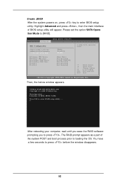
... POST and boot process prior to enter BIOS setup utility. Advanced BIOS SETUP UTILITY IDE Configuration OnBoard IDE Controller OnBoard SATA Controller SATA Operation Mode Primary IDE Master Primary IDE Slave Secondary IDE Master Secondary IDE Slave SATA1 SATA2 [Both] [Enabled] [RAID] [Hard Disk] [Not Detected] [ATAPI CDROM] [Not Detected] [Not Detected] [Not Detected] Config SATA operation mode. +F1 F10 ESC Select Screen Select Item Change Option General Help Save and Exit Exit v02.53 (C) Copyright 1985-2004. Then, the below window appears. NVIDIA RAID IDE ROM BIOS...
... POST and boot process prior to enter BIOS setup utility. Advanced BIOS SETUP UTILITY IDE Configuration OnBoard IDE Controller OnBoard SATA Controller SATA Operation Mode Primary IDE Master Primary IDE Slave Secondary IDE Master Secondary IDE Slave SATA1 SATA2 [Both] [Enabled] [RAID] [Hard Disk] [Not Detected] [ATAPI CDROM] [Not Detected] [Not Detected] [Not Detected] Config SATA operation mode. +F1 F10 ESC Select Screen Select Item Change Option General Help Save and Exit Exit v02.53 (C) Copyright 1985-2004. Then, the below window appears. NVIDIA RAID IDE ROM BIOS...


