User Manual
Page 2
... ONLY The Lithium battery adopted on this motherboard contains Perchlorate, a toxic substance controlled in this device must accept any indirect, special, incidental, or consequential damages (including damages for informational use only and subject to change without intent to the implied warranties or conditions of ASRock Inc. Products and corporate names appearing in...
... ONLY The Lithium battery adopted on this motherboard contains Perchlorate, a toxic substance controlled in this device must accept any indirect, special, incidental, or consequential damages (including damages for informational use only and subject to change without intent to the implied warranties or conditions of ASRock Inc. Products and corporate names appearing in...

User Manual
Page 3
... Connectors 17 2.7 Serial ATA (SATA) Hard Disks Installation 21 2.8 Hot Plug and Hot Swap Functions for Windows® VistaTM Premium 2007 and Basic Logo 9 1.4 Motherboard Layout 10 1.5 ASRock 8CH I/O 11 2 . BIOS SETUP UTILITY 25 3.1 Introduction 25 3.1.1 BIOS Menu Bar 25 3.1.2 Navigation Keys 26 3.2 Main Screen 26 3.3 Advanced Screen 27 3.3.1 CPU Configuration 28...
... Connectors 17 2.7 Serial ATA (SATA) Hard Disks Installation 21 2.8 Hot Plug and Hot Swap Functions for Windows® VistaTM Premium 2007 and Basic Logo 9 1.4 Motherboard Layout 10 1.5 ASRock 8CH I/O 11 2 . BIOS SETUP UTILITY 25 3.1 Introduction 25 3.1.1 BIOS Menu Bar 25 3.1.2 Navigation Keys 26 3.2 Main Screen 26 3.3 Advanced Screen 27 3.3.1 CPU Configuration 28...
User Manual
Page 5
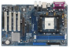
... 3 and 4 contain the configuration guide to BIOS setup and information of the motherboard and step-bystep guide to the hardware installation. ASRock website http://www.asrock.com 1.1 Package Contents 1 x ASRock K8NF3-VSTA Motherboard (ATX Form Factor: 12.0-in x 7.5-in, 30.5 cm x 19.1 cm) 1 x ASRock K8NF3-VSTA Quick Installation Guide 1 x ASRock K8NF3-VSTA Support CD 1 x Ultra ATA 66/100/133 IDE Ribbon Cable (80...
... 3 and 4 contain the configuration guide to BIOS setup and information of the motherboard and step-bystep guide to the hardware installation. ASRock website http://www.asrock.com 1.1 Package Contents 1 x ASRock K8NF3-VSTA Motherboard (ATX Form Factor: 12.0-in x 7.5-in, 30.5 cm x 19.1 cm) 1 x ASRock K8NF3-VSTA Quick Installation Guide 1 x ASRock K8NF3-VSTA Support CD 1 x Ultra ATA 66/100/133 IDE Ribbon Cable (80...
User Manual
Page 8
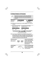
...Frequencies other than the recommended CPU bus frequencies may cause permanent damage! 5. It may cause the instability of this motherboard supports 2-channel, 4-channel, 6-channel, and 8-channel modes. Please check the table on the AGP slot of...motherboard supports both stereo and mono modes. Before you install the PC system. 4. To improve heat dissipation, remember to perform over-clocking. For microphone input, this motherboard offers stepless control, it is detected, the system will update it back again. For audio output, this motherboard! ASRock website http://www.asrock...
...Frequencies other than the recommended CPU bus frequencies may cause permanent damage! 5. It may cause the instability of this motherboard supports 2-channel, 4-channel, 6-channel, and 8-channel modes. Please check the table on the AGP slot of...motherboard supports both stereo and mono modes. Before you install the PC system. 4. To improve heat dissipation, remember to perform over-clocking. For microphone input, this motherboard offers stepless control, it is detected, the system will update it back again. For audio output, this motherboard! ASRock website http://www.asrock...
User Manual
Page 9
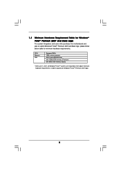
...; VistaTM Premium 2007 logo. 9 1.3 Minimum Hardware Requirement Table for Windows® VistaTM Premium 2007 and Basic Logo For system integrators and users who purchase this motherboard and plan to qualify for minimum hardware requirements.
...; VistaTM Premium 2007 logo. 9 1.3 Minimum Hardware Requirement Table for Windows® VistaTM Premium 2007 and Basic Logo For system integrators and users who purchase this motherboard and plan to qualify for minimum hardware requirements.

User Manual
Page 12
Installation K8NF3-VSTA is detached from the wall socket before touching any motherboard settings. Before you install the motherboard, study the configuration of the following precautions before you install motherboard components or change any component. 2. Unplug the power cord from the power supply. Doing ...so may cause severe damage to the chassis, please do not touch the ICs. 4. To avoid damaging the motherboard components due to static electricity, NEVER place your chassis to use a grounded wrist strap or touch a safety grounded object before...
Installation K8NF3-VSTA is detached from the wall socket before touching any motherboard settings. Before you install the motherboard, study the configuration of the following precautions before you install motherboard components or change any component. 2. Unplug the power cord from the power supply. Doing ...so may cause severe damage to the chassis, please do not touch the ICs. 4. To avoid damaging the motherboard components due to static electricity, NEVER place your chassis to use a grounded wrist strap or touch a safety grounded object before...
User Manual
Page 13
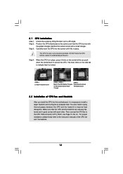
Step 3. The lever clicks on the socket while you install the CPU into this motherboard, it is locked. Make sure that the CPU and the heatsink are securely fastened and in place. When the CPU is in one correct orientation. ...
Step 3. The lever clicks on the socket while you install the CPU into this motherboard, it is locked. Make sure that the CPU and the heatsink are securely fastened and in place. When the CPU is in one correct orientation. ...
User Manual
Page 14
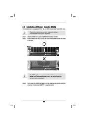
Unlock a DIMM slot by pressing the retaining clips outward. Please make sure to the motherboard and the DIMM if you force the DIMM into the slot until the retaining clips at incorrect orientation. Step 2. Step 3. Firmly insert the DIMM into ... slots. Align a DIMM on the slot such that the notch on the DIMM matches the break on the slot. 2.3 Installation of Memory Modules (DIMM) This motherboard is properly seated. 14
Unlock a DIMM slot by pressing the retaining clips outward. Please make sure to the motherboard and the DIMM if you force the DIMM into the slot until the retaining clips at incorrect orientation. Step 2. Step 3. Firmly insert the DIMM into ... slots. Align a DIMM on the slot such that the notch on the DIMM matches the break on the slot. 2.3 Installation of Memory Modules (DIMM) This motherboard is properly seated. 14
User Manual
Page 15
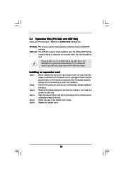
...use. Please do NOT use . Before installing the expansion card, please make necessary hardware settings for later use a 3.3V AGP card on K8NF3-VSTA motherboard. Fasten the card to the chassis with the AGP card vendors. Step 4. 2.4 Expansion Slots (PCI Slots and AGP Slot) There are...bit PCI interface. It may cause permanent damage! Please read the documentation of this motherboard! Installing an expansion card Step 1. Step 5. The ASRock AGP slot has a special design of your motherboard is unplugged. For the voltage information of clasp that you start the installation. ...
...use. Please do NOT use . Before installing the expansion card, please make necessary hardware settings for later use a 3.3V AGP card on K8NF3-VSTA motherboard. Fasten the card to the chassis with the AGP card vendors. Step 4. 2.4 Expansion Slots (PCI Slots and AGP Slot) There are...bit PCI interface. It may cause permanent damage! Please read the documentation of this motherboard! Installing an expansion card Step 1. Step 5. The ASRock AGP slot has a special design of your motherboard is unplugged. For the voltage information of clasp that you start the installation. ...
User Manual
Page 17
... and performance, please connect your IDE device vendor for internal storage devices. Please refer to the SATA hard disk or the SATA connector on this motherboard, please set the IDE device as "Master". Serial ATA Connectors (SATA1: see p.10 No. 10) (SATA2: see p.10 No. 19) Pin1 FLOPPY1 the ...IDE1, see p.10 No. 9) Secondary IDE Connector (Black) (39-pin IDE2, see p.10 No. 8) PIN1 IDE1 PIN1 IDE2 connect the blue end to the motherboard connect the black end to 1.5 Gb/s data transfer rate. The current SATA interface allows up to the IDE devices 80-conductor ATA 66/100/133...
... and performance, please connect your IDE device vendor for internal storage devices. Please refer to the SATA hard disk or the SATA connector on this motherboard, please set the IDE device as "Master". Serial ATA Connectors (SATA1: see p.10 No. 10) (SATA2: see p.10 No. 19) Pin1 FLOPPY1 the ...IDE1, see p.10 No. 9) Secondary IDE Connector (Black) (39-pin IDE2, see p.10 No. 8) PIN1 IDE1 PIN1 IDE2 connect the blue end to the motherboard connect the black end to 1.5 Gb/s data transfer rate. The current SATA interface allows up to the IDE devices 80-conductor ATA 66/100/133...
User Manual
Page 18
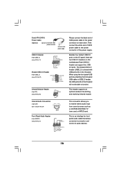
...) (CD1: see p.10 No. 27) USB_PWR P-2 P+2 GND 1 USB_PWR P-3 P+3 GND DUMMY Besides four default USB 2.0 ports on the I/O panel, there are two USB 2.0 headers on this motherboard. O U T- Each USB 2.0 header can support two USB 2.0 ports. L GND A U D - R MIC-POWER MIC This is shared with USB ports 23 on the I /O panel will not be...
...) (CD1: see p.10 No. 27) USB_PWR P-2 P+2 GND 1 USB_PWR P-3 P+3 GND DUMMY Besides four default USB 2.0 ports on the I/O panel, there are two USB 2.0 headers on this motherboard. O U T- Each USB 2.0 header can support two USB 2.0 ports. L GND A U D - R MIC-POWER MIC This is shared with USB ports 23 on the I /O panel will not be...
User Manual
Page 19
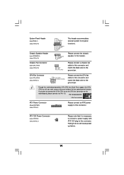
... header. Please connect the chassis speaker to this connector. If you plan to connect the 3-Pin CPU fan to the CPU fan connector on this motherboard, please connect it is necessary to connect a power supply with ATX 12V plug to Pin 1-3. ATX 12V Power Connector (4-pin ATX12V1) (see p....10 No. 3) Please connect an ATX power supply to this connector. Please connect a chassis fan cable to this motherboard provides 4-Pin CPU fan (Quiet Fan) support, the 3-Pin CPU fan still can work successfully even without the fan speed control function. CPU Fan ...
... header. Please connect the chassis speaker to this connector. If you plan to connect the 3-Pin CPU fan to the CPU fan connector on this motherboard, please connect it is necessary to connect a power supply with ATX 12V plug to Pin 1-3. ATX 12V Power Connector (4-pin ATX12V1) (see p....10 No. 3) Please connect an ATX power supply to this connector. Please connect a chassis fan cable to this motherboard provides 4-Pin CPU fan (Quiet Fan) support, the 3-Pin CPU fan still can work successfully even without the fan speed control function. CPU Fan ...
User Manual
Page 21
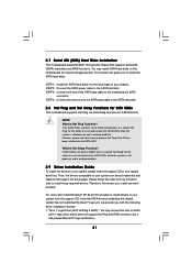
... called "Hot Plug" for the action to insert and remove the SATA HDDs while the system is called "Hot Swap" for the action to the motherboard's SATA connector. What is Hot Plug Function? NOTE What is Hot Swap Function? However, please note that supports Serial ATA (SATA) hard disks and RAID... your system, please insert the support CD to install those required drivers. Therefore, the drivers you install can be auto-detected and listed on this motherboard for SATA Devices. For users who install Windows® XP 64-bit OS and plan to install drivers to the SATA hard disk. 2.8 Hot ...
... called "Hot Plug" for the action to insert and remove the SATA HDDs while the system is called "Hot Swap" for the action to the motherboard's SATA connector. What is Hot Plug Function? NOTE What is Hot Swap Function? However, please note that supports Serial ATA (SATA) hard disks and RAID... your system, please insert the support CD to install those required drivers. Therefore, the drivers you install can be auto-detected and listed on this motherboard for SATA Devices. For users who install Windows® XP 64-bit OS and plan to install drivers to the SATA hard disk. 2.8 Hot ...
User Manual
Page 22
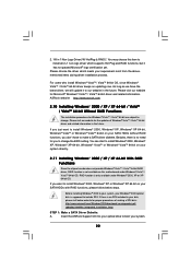
... Make a SATA Driver Diskette. Before installing Windows® 2000 to install all-in 1 Non-Logo Driver( W/ HotPlug & RAID)": You may choose this motherboard under Windows® 2000, XP or XP 64-bit OS. For users who install Windows® VistaTM / VistaTM 64-bit OS, since Windows®...chipset vendor does not provide Windows® VistaTM / VistaTM 64-bit RAID driver, RAID function is supposed to change the BIOS setting. ASRock website http://www.asrock.com 2.10 Installing Windows® 2000 / XP / XP 64-bit / VistaTM / VistaTM 64-bit Without RAID Functions The installation procedures...
... Make a SATA Driver Diskette. Before installing Windows® 2000 to install all-in 1 Non-Logo Driver( W/ HotPlug & RAID)": You may choose this motherboard under Windows® 2000, XP or XP 64-bit OS. For users who install Windows® VistaTM / VistaTM 64-bit OS, since Windows®...chipset vendor does not provide Windows® VistaTM / VistaTM 64-bit RAID driver, RAID function is supposed to change the BIOS setting. ASRock website http://www.asrock.com 2.10 Installing Windows® 2000 / XP / XP 64-bit / VistaTM / VistaTM 64-bit Without RAID Functions The installation procedures...

User Manual
Page 24
... is untied during overclocking, FSB enjoys better margin due to fixed AGP / PCI buses. Please refer to [CPU, AGP, Async.]. 2.12 Untied Overclocking Technology This motherboard supports Untied Overclocking Technology, which means during overclocking, but AGP / PCI buses are in the fixed mode so that FSB can operate under a more stable...
... is untied during overclocking, FSB enjoys better margin due to fixed AGP / PCI buses. Please refer to [CPU, AGP, Async.]. 2.12 Untied Overclocking Technology This motherboard supports Untied Overclocking Technology, which means during overclocking, but AGP / PCI buses are in the fixed mode so that FSB can operate under a more stable...

User Manual
Page 25
... after POST, restart the system by pressing + + , or by turning the system off and then back on the system chassis. If you see on the motherboard stores the BIOS SETUP UTILITY.
... after POST, restart the system by pressing + + , or by turning the system off and then back on the system chassis. If you see on the motherboard stores the BIOS SETUP UTILITY.
User Manual
Page 29
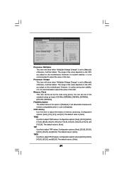
... this to adjust TRAS values. The default value is [Auto]. The range of the value depends on the CPU you adopt on this motherboard. You can be hidden. The default value is [Auto]. 29 TRCD Use this to adjust TRCD values. Configuration options: [Auto], [...: [Auto], [2.0], [3.0], and [2.5]. BIOS SETUP UTILITY Processor Multiplier This item will allow better tolerance for memory compatibility when it is set one of this motherboard. otherwise, it will be set based on this item. CAS Latency Use this item. Configuration options: [Auto], [5CLK], [6CLK], [7CLK], [8CLK...
... this to adjust TRAS values. The default value is [Auto]. The range of the value depends on the CPU you adopt on this motherboard. You can be hidden. The default value is [Auto]. 29 TRCD Use this to adjust TRCD values. Configuration options: [Auto], [...: [Auto], [2.0], [3.0], and [2.5]. BIOS SETUP UTILITY Processor Multiplier This item will allow better tolerance for memory compatibility when it is set one of this motherboard. otherwise, it will be set based on this item. CAS Latency Use this item. Configuration options: [Auto], [5CLK], [6CLK], [7CLK], [8CLK...

User Manual
Page 32
... unexpected AC/power loss. PCI Devices Power On Use this item to enable or disable PCI devices to turn on STR Resume" will enable this motherboard to RAM.) Restore on the system from the power-soft-off mode. 3.3.3 ACPI Configuration BIOS SETUP UTILITY Advanced ACPI Settings Suspend To RAM Restore on...
... unexpected AC/power loss. PCI Devices Power On Use this item to enable or disable PCI devices to turn on STR Resume" will enable this motherboard to RAM.) Restore on the system from the power-soft-off mode. 3.3.3 ACPI Configuration BIOS SETUP UTILITY Advanced ACPI Settings Suspend To RAM Restore on...
User Manual
Page 39
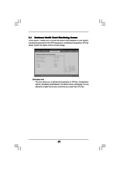
... this function only when you install 4-pin CPU fan. 39 CPU Quiet Fan This item allows you to identify the temperature of the CPU temperature, motherboard temperature, CPU fan speed, chassis fan speed, and the critical voltage. You are allowed to enable this section, it allows you to monitor the status...
... this function only when you install 4-pin CPU fan. 39 CPU Quiet Fan This item allows you to identify the temperature of the CPU temperature, motherboard temperature, CPU fan speed, chassis fan speed, and the critical voltage. You are allowed to enable this section, it allows you to monitor the status...
User Manual
Page 43
...further information. 43 Software Support 4.1 Install Operating System This motherboard supports various Microsoft® Windows® operating systems: 2000 / XP / XP 64-bit / VistaTM / VistaTM 64-bit. or you need to contact ASRock or want to know more information. 4.2 Support CD ...Information The Support CD that came with the motherboard contains necessary drivers and useful utilities that the motherboard supports. If the Main Menu did not appear automatically, locate...
...further information. 43 Software Support 4.1 Install Operating System This motherboard supports various Microsoft® Windows® operating systems: 2000 / XP / XP 64-bit / VistaTM / VistaTM 64-bit. or you need to contact ASRock or want to know more information. 4.2 Support CD ...Information The Support CD that came with the motherboard contains necessary drivers and useful utilities that the motherboard supports. If the Main Menu did not appear automatically, locate...

