User Manual
Page 3
... 18 2.8 Making a SATA Driver Diskette For SATA Operation in "RAID" Mode 19 2.9 SATA Operating in "non-RAID" Mode 19 3 . BIOS SETUP UTILITY 20 3.1 Introduction 20 3.1.1 BIOS Menu Bar 20 3.1.2 Navigation Keys 21 3.2 Main Screen 21 3.3 Advanced Screen 22 3.3.1 CPU Configuration 22 3.3.2 Chipset Configuration 25 3.3.3 ACPI Configuration 26... Boot Settings Configuration 33 3.5.2 Boot Device Priority 34 3.6 Security Screen 34 3.7 Exit Screen 35 3 Introduction 5 1.1 Package Contents 5 1.2 Specifications 6 1.3 Motherboard Layout 8 1.4 ASRock I/O Plus 9 TM ...2 . Contents 1 .
... 18 2.8 Making a SATA Driver Diskette For SATA Operation in "RAID" Mode 19 2.9 SATA Operating in "non-RAID" Mode 19 3 . BIOS SETUP UTILITY 20 3.1 Introduction 20 3.1.1 BIOS Menu Bar 20 3.1.2 Navigation Keys 21 3.2 Main Screen 21 3.3 Advanced Screen 22 3.3.1 CPU Configuration 22 3.3.2 Chipset Configuration 25 3.3.3 ACPI Configuration 26... Boot Settings Configuration 33 3.5.2 Boot Device Priority 34 3.6 Security Screen 34 3.7 Exit Screen 35 3 Introduction 5 1.1 Package Contents 5 1.2 Specifications 6 1.3 Motherboard Layout 8 1.4 ASRock I/O Plus 9 TM ...2 . Contents 1 .
User Manual
Page 5
...BIOS setup and information of the motherboard and step-bystep guide to quality and endurance. You may find the latest memory and CPU support lists on ASRock website without notice. Introduction Thank you for purchasing ASRock K8A8X-M motherboard, a reliable motherboard produced under ASRock...the configuration guide to change without further notice. ASRock website http://www.asrock.com 1.1 Package Contents 1 x ASRock K8A8X-M Motherboard (Micro ATX Form Factor: 9.6-in x 7.8-in, 24.4 cm x 19.8 cm) 1 x ASRock K8A8X-M Quick Installation Guide 1 x ASRock K8A8X-M Support CD 1 x Ultra ATA 66/...
...BIOS setup and information of the motherboard and step-bystep guide to quality and endurance. You may find the latest memory and CPU support lists on ASRock website without notice. Introduction Thank you for purchasing ASRock K8A8X-M motherboard, a reliable motherboard produced under ASRock...the configuration guide to change without further notice. ASRock website http://www.asrock.com 1.1 Package Contents 1 x ASRock K8A8X-M Motherboard (Micro ATX Form Factor: 9.6-in x 7.8-in, 24.4 cm x 19.8 cm) 1 x ASRock K8A8X-M Quick Installation Guide 1 x ASRock K8A8X-M Support CD 1 x Ultra ATA 66/...

User Manual
Page 7
... perform over-clocking. Power Management for advanced users' reference, see CAUTION 4) Microsoft® Windows® 98SE / ME / 2000 / XP compliant CAUTION! 1. Although this motherboard! BIOS: OS: AMI BIOS Supports "Plug and Play" ACPI 1.1 compliance wake up events SMBIOS 2.3.1 support CPU frequency stepless control (only for USB 2.0 works fine under Microsoft® Windows...
... perform over-clocking. Power Management for advanced users' reference, see CAUTION 4) Microsoft® Windows® 98SE / ME / 2000 / XP compliant CAUTION! 1. Although this motherboard! BIOS: OS: AMI BIOS Supports "Plug and Play" ACPI 1.1 compliance wake up events SMBIOS 2.3.1 support CPU frequency stepless control (only for USB 2.0 works fine under Microsoft® Windows...

User Manual
Page 8
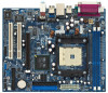
... 1 USB 2.0 T: USB4 B: USB5 USB4_5 AUX1 CD1 LAN PHY 1 AUDIO1 JR1 JL1 AGP 8X FSB800 ALi M1689 Chipset SATA SATA2 SATA1 AUDIO CODEC 2MB BIOS AMR1 1.5V_AGP1 CLRTC1 1 USB2.0 PCI 1 K8A8X-M 5.1CH FLOPPY1 CMOS Battery PCI 2 CHA_FAN1 1 GAME1 USB67 1 SPEAKER1 1 IR1 1 PLED PWRBTN PANEL 1 1 HDLED RESET 20 19 18 17 16 15 8 9 10...
... 1 USB 2.0 T: USB4 B: USB5 USB4_5 AUX1 CD1 LAN PHY 1 AUDIO1 JR1 JL1 AGP 8X FSB800 ALi M1689 Chipset SATA SATA2 SATA1 AUDIO CODEC 2MB BIOS AMR1 1.5V_AGP1 CLRTC1 1 USB2.0 PCI 1 K8A8X-M 5.1CH FLOPPY1 CMOS Battery PCI 2 CHA_FAN1 1 GAME1 USB67 1 SPEAKER1 1 IR1 1 PLED PWRBTN PANEL 1 1 HDLED RESET 20 19 18 17 16 15 8 9 10...
User Manual
Page 18
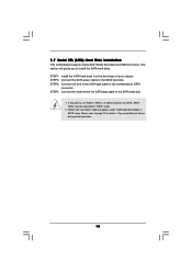
... power cable to install the SATA hard disks. Please refer to use RAID 0, RAID 1, or JBOD functions on SATA, SATA HDDs must be operated in BIOS setup. They need different drivers during actual operation. 18 If you to the SATA hard disk. STEP 3: Connect one end of the SATA data cable...
... power cable to install the SATA hard disks. Please refer to use RAID 0, RAID 1, or JBOD functions on SATA, SATA HDDs must be operated in BIOS setup. They need different drivers during actual operation. 18 If you to the SATA hard disk. STEP 3: Connect one end of the SATA data cable...
User Manual
Page 19
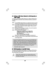
... the SATA driver diskette ready, you may start to make a SATA driver diskette before OS installation. 19 Before you start to use "ALi RAID BIOS Setup Utility" to set RAID 0 / RAID 1 / JBOD configuration before you need to configure the RAID function, you install the OS. STEP 1: Insert the... ASRock Support CD into your optical drive to boot your system. (Do NOT insert any floppy diskette into the floppy drive. Please select CDROM as the ...
... the SATA driver diskette ready, you may start to make a SATA driver diskette before OS installation. 19 Before you start to use "ALi RAID BIOS Setup Utility" to set RAID 0 / RAID 1 / JBOD configuration before you need to configure the RAID function, you install the OS. STEP 1: Insert the... ASRock Support CD into your optical drive to boot your system. (Do NOT insert any floppy diskette into the floppy drive. Please select CDROM as the ...

User Manual
Page 20
...screens and descriptions are for reference purpose only, and they may not exactly match what you see on your system. BIOS SETUP UTILITY 3.1 Introduction This section explains how to use the BIOS SETUP UTILITY to choose among the selections on . You may also restart by pressing the reset button on the ... then back on the menu bar, and then press to locate and load the Operating System Security To set up the computer. Because the BIOS software is constantly being updated, the following selections: Main To set up the system time/date information Advanced To set up the advanced...
...screens and descriptions are for reference purpose only, and they may not exactly match what you see on your system. BIOS SETUP UTILITY 3.1 Introduction This section explains how to use the BIOS SETUP UTILITY to choose among the selections on . You may also restart by pressing the reset button on the ... then back on the menu bar, and then press to locate and load the Operating System Security To set up the computer. Because the BIOS software is constantly being updated, the following selections: Main To set up the system time/date information Advanced To set up the advanced...

User Manual
Page 21
...Please check the following table for all the settings To save changes and exit the BIOS SETUP UTILITY To jump to the Exit Screen or exit the current screen 3.2 Main Screen When you enter the BIOS SETUP UTILITY, the Main screen will appear and display the system overview System Overview... System Time System Date [17:00:09] [Tue 04/26/2005] BIOS Version : K8A8X-M BIOS P1.0 Processor Type : AMD Athlon(tm) 64 Processor 3400+ Processor Speed : 2200 MHz L1 Cache Size : 128KB L2 Cache Size : 1024KB Total Memory ...
...Please check the following table for all the settings To save changes and exit the BIOS SETUP UTILITY To jump to the Exit Screen or exit the current screen 3.2 Main Screen When you enter the BIOS SETUP UTILITY, the Main screen will appear and display the system overview System Overview... System Time System Date [17:00:09] [Tue 04/26/2005] BIOS Version : K8A8X-M BIOS P1.0 Processor Type : AMD Athlon(tm) 64 Processor 3400+ Processor Speed : 2200 MHz L1 Cache Size : 128KB L2 Cache Size : 1024KB Total Memory ...
User Manual
Page 22
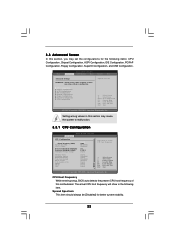
... Configuration USB Configuration Options for CPU Select Screen Select Item Enter Go to malfunction. CPU Host Frequency While entering setup, BIOS auto detects the present CPU host frequency of this section may cause system to Sub Screen F1 General Help F9 Load..., and USB Configuration. The actual CPU host frequency will show in below sections may cause the system to malfunction. 3.3.1 CPU Configuration BIOS SETUP UTILITY Advanced CPU Configuration CPU Host Frequency Actual Frequency (MHz) Spread Spectrum Cool' n' Quiet Processor Maximum Multiplier Processor Maximum Voltage ...
... Configuration USB Configuration Options for CPU Select Screen Select Item Enter Go to malfunction. CPU Host Frequency While entering setup, BIOS auto detects the present CPU host frequency of this section may cause system to Sub Screen F1 General Help F9 Load..., and USB Configuration. The actual CPU host frequency will show in below sections may cause the system to malfunction. 3.3.1 CPU Configuration BIOS SETUP UTILITY Advanced CPU Configuration CPU Host Frequency Actual Frequency (MHz) Spread Spectrum Cool' n' Quiet Processor Maximum Multiplier Processor Maximum Voltage ...
User Manual
Page 23
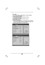
Processor Maximum Voltage It will display Processor Maximum Multiplier for reference. BIOS SETUP UTILITY Advanced CPU Configuration CPU Host Frequency Actual Frequency (MHz) Spread Spectrum Cool' n' Quiet Processor Maximum Multiplier ..., FID/VID will be left at the rated frequency/voltage. Processor Maximum Multiplier It will display Processor Maximum Voltage for system stability. BIOS SETUP UTILITY Advanced Cool' n' Quiet Processor Maximum Multiplier Processor Maximum Voltage Multiplier/Voltage Change Processor Multiplier Processor Voltage Memory Clock Flexibility Option Bank...
Processor Maximum Voltage It will display Processor Maximum Multiplier for reference. BIOS SETUP UTILITY Advanced CPU Configuration CPU Host Frequency Actual Frequency (MHz) Spread Spectrum Cool' n' Quiet Processor Maximum Multiplier ..., FID/VID will be left at the rated frequency/voltage. Processor Maximum Multiplier It will display Processor Maximum Voltage for system stability. BIOS SETUP UTILITY Advanced Cool' n' Quiet Processor Maximum Multiplier Processor Maximum Voltage Multiplier/Voltage Change Processor Multiplier Processor Voltage Memory Clock Flexibility Option Bank...

User Manual
Page 27
... the integrated IDE Controller. SECONDARY: enables only the Secondary IDE Controller. Or you may enable either the primary IDE channel or the secondary IDE channel. BIOS SETUP UTILITY Advanced Primary IDE Master Device Vendor Size LBA Mode Block Mode PIO Mode Async DMA Ultra DMA S.M.A.R.T. :Hard Disk :MAXTOR 6L080J4 :80.0 GB...
... the integrated IDE Controller. SECONDARY: enables only the Secondary IDE Controller. Or you may enable either the primary IDE channel or the secondary IDE channel. BIOS SETUP UTILITY Advanced Primary IDE Master Device Vendor Size LBA Mode Block Mode PIO Mode Async DMA Ultra DMA S.M.A.R.T. :Hard Disk :MAXTOR 6L080J4 :80.0 GB...

User Manual
Page 28
... capability allows the improved transfer-speed and data-integrity for a hard disk > 512 MB under DOS and Windows; After selecting the hard disk information into BIOS, use of IDE device. [Auto]: Select [Auto] to automatically detect the hard disk drive. PIO Mode Use this item to set the partition of the...
... capability allows the improved transfer-speed and data-integrity for a hard disk > 512 MB under DOS and Windows; After selecting the hard disk information into BIOS, use of IDE device. [Auto]: Select [Auto] to automatically detect the hard disk drive. PIO Mode Use this item to set the partition of the...

User Manual
Page 30
... item to set the address for the onboard serial port or disable it . Configuration options: [Disabled], [2F8 / IRQ3], and [2E8 / IRQ3]. 30 BIOS SETUP UTILITY Advanced Floppy Configuration Floppy A Floppy B [1.44 MB 312"] [Disabled] Select the type of your floppy drive. Configuration options: [Disabled], [3F8... Port OnBoard MIDI Port [Enabled] [3F8 / IRQ4] [Disabled] [378] [ECP + EPP] [1.9] [DMA3] [IRQ7] [Enabled] [Disabled] Allow BIOS to Enable or Disable Floppy Controller. +F1 F9 F10 ESC Select Screen Select Item Change Option General Help Load Defaults Save and Exit Exit v02...
... item to set the address for the onboard serial port or disable it . Configuration options: [Disabled], [2F8 / IRQ3], and [2E8 / IRQ3]. 30 BIOS SETUP UTILITY Advanced Floppy Configuration Floppy A Floppy B [1.44 MB 312"] [Disabled] Select the type of your floppy drive. Configuration options: [Disabled], [3F8... Port OnBoard MIDI Port [Enabled] [3F8 / IRQ4] [Disabled] [378] [ECP + EPP] [1.9] [DMA3] [IRQ7] [Enabled] [Disabled] Allow BIOS to Enable or Disable Floppy Controller. +F1 F9 F10 ESC Select Screen Select Item Change Option General Help Load Defaults Save and Exit Exit v02...

User Manual
Page 32
..., and the critical voltage. if there is no USB device connected, "Auto" option will start to enable or disable the USB 2.0 support. etc. 3.3.8 USB Configuration BIOS SETUP UTILITY Advanced USB Configuration USB Controller USB 2.0 Support Legacy USB Support [Enabled] [Enabled] [Disabled] To enable or disable the onboard USB controllers. +F1 F9...
..., and the critical voltage. if there is no USB device connected, "Auto" option will start to enable or disable the USB 2.0 support. etc. 3.3.8 USB Configuration BIOS SETUP UTILITY Advanced USB Configuration USB Controller USB 2.0 Support Legacy USB Support [Enabled] [Enabled] [Disabled] To enable or disable the onboard USB controllers. +F1 F9...

User Manual
Page 34
For the user password, you may also clear it. BIOS SETUP UTILITY Boot Boot Device Priority 1st Boot Device 2nd Boot Device 3rd Boot Device [1st FLOPPY DRIVE] [HDD: PM-MAXTOR 6L08] [CD / DVD: SM-...
For the user password, you may also clear it. BIOS SETUP UTILITY Boot Boot Device Priority 1st Boot Device 2nd Boot Device 3rd Boot Device [1st FLOPPY DRIVE] [HDD: PM-MAXTOR 6L08] [CD / DVD: SM-...

User Manual
Page 35
... this option, it will pop-out the following message, "Load optimal defaults?" Select [OK] to save the changes and exit the BIOS SETUP UTILITY. Select [OK] to exit the BIOS SETUP UTILITY without saving any changes. Load Optimal Defaults When you select this option, it will pop-out the following message, "Discard...
... this option, it will pop-out the following message, "Load optimal defaults?" Select [OK] to save the changes and exit the BIOS SETUP UTILITY. Select [OK] to exit the BIOS SETUP UTILITY without saving any changes. Load Optimal Defaults When you select this option, it will pop-out the following message, "Discard...


