User Manual
Page 3
... of CPU Fan and Heatsink 11 2.3 Installation of Memory Modules (DIMM 12 2.4 Expansion Slots (PCI and AGP Slots 13 2.5 Jumpers Setup 14 2.6 Onboard Headers and Connectors 15 2.7 Serial ATA (SATA) Hard Disks Installation 18 2.8 Making a SATA Driver Diskette For SATA Operation in "RAID" Mode 19 2.9 SATA Operating in "non-RAID" Mode 19 3 . BIOS SETUP UTILITY 20 3.1 Introduction 20 3.1.1 BIOS Menu Bar 20 3.1.2 Navigation Keys 21 3.2 Main Screen 21 3.3 Advanced Screen 22 3.3.1 CPU Configuration 22 3.3.2 Chipset Configuration 25 3.3.3 ACPI Configuration 26 3.3.4 IDE Configuration 27...
... of CPU Fan and Heatsink 11 2.3 Installation of Memory Modules (DIMM 12 2.4 Expansion Slots (PCI and AGP Slots 13 2.5 Jumpers Setup 14 2.6 Onboard Headers and Connectors 15 2.7 Serial ATA (SATA) Hard Disks Installation 18 2.8 Making a SATA Driver Diskette For SATA Operation in "RAID" Mode 19 2.9 SATA Operating in "non-RAID" Mode 19 3 . BIOS SETUP UTILITY 20 3.1 Introduction 20 3.1.1 BIOS Menu Bar 20 3.1.2 Navigation Keys 21 3.2 Main Screen 21 3.3 Advanced Screen 22 3.3.1 CPU Configuration 22 3.3.2 Chipset Configuration 25 3.3.3 ACPI Configuration 26 3.3.4 IDE Configuration 27...
User Manual
Page 5
... memory and CPU support lists on ASRock website without notice. Chapter 3 and 4 contain the configuration guide to BIOS setup and information of this manual occur, the updated version will be available on ASRock website as well. ASRock website http://www.asrock.com 1.1 Package Contents 1 x ASRock K8A8X-M Motherboard (Micro ATX Form Factor: 9.6-in x 7.8-in, 24.4 cm x 19.8 cm) 1 x ASRock K8A8X-M Quick Installation Guide 1 x ASRock K8A8X-M Support CD 1 x Ultra ATA 66/100/133 IDE Ribbon Cable (80-conductor) 1 x 3.5-in Floppy Drive Ribbon Cable 1 x Serial...
... memory and CPU support lists on ASRock website without notice. Chapter 3 and 4 contain the configuration guide to BIOS setup and information of this manual occur, the updated version will be available on ASRock website as well. ASRock website http://www.asrock.com 1.1 Package Contents 1 x ASRock K8A8X-M Motherboard (Micro ATX Form Factor: 9.6-in x 7.8-in, 24.4 cm x 19.8 cm) 1 x ASRock K8A8X-M Quick Installation Guide 1 x ASRock K8A8X-M Support CD 1 x Ultra ATA 66/100/133 IDE Ribbon Cable (80-conductor) 1 x 3.5-in Floppy Drive Ribbon Cable 1 x Serial...

User Manual
Page 6
... 2 floppy disk drives Audio: 5.1 channels AC'97 Audio LAN: Speed: 802.3u (10/100 Ethernet), supports Wake-On-LAN Hardware Monitor: CPU temperature sensing Motherboard temperature sensing CPU overheat shutdown to protect CPU life (ASRock U-COP)(see CAUTION 1) CPU fan tachometer Chassis fan tachometer Voltage monitoring: +12V, +5V, +3.3V, Vcore PCI Slots: 2 x PCI slots, PCI specification 2.1 AGP Slot: 1 x AGP slot Supports 1.5V, 8X / 4X AGP card (see CAUTION 2) USB 2.0: 8 x USB 2.0 ports: 6 ready-to-use USB 2.0 ports on the I/O panel, plus 1 on-board header supporting 2 extra...
... 2 floppy disk drives Audio: 5.1 channels AC'97 Audio LAN: Speed: 802.3u (10/100 Ethernet), supports Wake-On-LAN Hardware Monitor: CPU temperature sensing Motherboard temperature sensing CPU overheat shutdown to protect CPU life (ASRock U-COP)(see CAUTION 1) CPU fan tachometer Chassis fan tachometer Voltage monitoring: +12V, +5V, +3.3V, Vcore PCI Slots: 2 x PCI slots, PCI specification 2.1 AGP Slot: 1 x AGP slot Supports 1.5V, 8X / 4X AGP card (see CAUTION 2) USB 2.0: 8 x USB 2.0 ports: 6 ready-to-use USB 2.0 ports on the I/O panel, plus 1 on-board header supporting 2 extra...

User Manual
Page 7
BIOS: OS: AMI BIOS Supports "Plug and Play" ACPI 1.1 compliance wake up events SMBIOS 2.3.1 support CPU frequency stepless control (only for USB 2.0 works fine under Microsoft® Windows® 98 / ME. 4. Frequencies other than the recommended CPU FSB frequencies may cause the instability of this motherboard offers stepless control, it back again. It may cause permanent damage! 3. While CPU overheat is not recommended to spray thermal grease between the CPU and...
BIOS: OS: AMI BIOS Supports "Plug and Play" ACPI 1.1 compliance wake up events SMBIOS 2.3.1 support CPU frequency stepless control (only for USB 2.0 works fine under Microsoft® Windows® 98 / ME. 4. Frequencies other than the recommended CPU FSB frequencies may cause the instability of this motherboard offers stepless control, it back again. It may cause permanent damage! 3. While CPU overheat is not recommended to spray thermal grease between the CPU and...

User Manual
Page 8
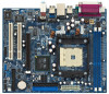
... 3 CPU Socket 4 CPU Heatsink Retention Module 5 2 x 184-pin DDR DIMM Slots (DDR1- 2) 6 CPU Fan Connector (CPU_FAN1) 7 ATX Power Connector (ATXPWR1) 8 Secondary Serial ATA Connector (SATA2) 9 Primary Serial ATA Connector (SATA1) 10 Primary IDE Connector (IDE1, Blue) 11 Secondary IDE Connector (IDE2, Black) 12 Clear CMOS Jumper (CLRTC1) 13 Floppy Connector (FLOPPY1) 14 Chassis Fan Connector (CHA_FAN1) 15 System Panel Header (PANEL1) 16 Infrared Module Header (IR1) 17 Chassis Speaker Header (SPEAKER 1) 18 USB 2.0 Header (USB67, Blue) 19 Game Port Header (GAME1) 20 AMR Slot (AMR1) 21 Flash Memory...
... 3 CPU Socket 4 CPU Heatsink Retention Module 5 2 x 184-pin DDR DIMM Slots (DDR1- 2) 6 CPU Fan Connector (CPU_FAN1) 7 ATX Power Connector (ATXPWR1) 8 Secondary Serial ATA Connector (SATA2) 9 Primary Serial ATA Connector (SATA1) 10 Primary IDE Connector (IDE1, Blue) 11 Secondary IDE Connector (IDE2, Black) 12 Clear CMOS Jumper (CLRTC1) 13 Floppy Connector (FLOPPY1) 14 Chassis Fan Connector (CHA_FAN1) 15 System Panel Header (PANEL1) 16 Infrared Module Header (IR1) 17 Chassis Speaker Header (SPEAKER 1) 18 USB 2.0 Header (USB67, Blue) 19 Game Port Header (GAME1) 20 AMR Slot (AMR1) 21 Flash Memory...

User Manual
Page 16
Internal Audio Connectors (4-pin CD1, 4-pin AUX1) (CD1: see p.8, No. 28) (AUX1: see p.8, No. 27) AUX-R GND GND AUX-L AUX1 CD-R GND GND CD-L CD1 These connectors allow you 6 ready-to-use USB 2.0 ports on the drive. O U T- When using the front panel USB ports by attaching the front panel USB cable to this USB 2.0 header is shared with the USB 2.0 ports 4,5 on ASRock I/O PlusTM. L GND A U D - Serial ATA (SATA) Power Cable (Optional) connect to the SATA HDD power connector connect to the power supply Please connect the black...
Internal Audio Connectors (4-pin CD1, 4-pin AUX1) (CD1: see p.8, No. 28) (AUX1: see p.8, No. 27) AUX-R GND GND AUX-L AUX1 CD-R GND GND CD-L CD1 These connectors allow you 6 ready-to-use USB 2.0 ports on the drive. O U T- When using the front panel USB ports by attaching the front panel USB cable to this USB 2.0 header is shared with the USB 2.0 ports 4,5 on ASRock I/O PlusTM. L GND A U D - Serial ATA (SATA) Power Cable (Optional) connect to the SATA HDD power connector connect to the power supply Please connect the black...

User Manual
Page 17
... is installed. Chassis Fan Connector (3-pin CHA_FAN1) (see p.8, No. 14) CPU Fan Connector (3-pin CPU_FAN1) (see p.8, No. 6) Game Connector (15-pin GAME1) (see p.8, No. 19) ATX Power Connector (20-pin ATXPWR1) (see p.8, No. 17) PLED+ PLEDPWRBTN# GND 1 DUMMY RESET# GND HDLEDHDLED+ 1 SPEAKER DUMMY DUMMY +5V This header accommodates several system front panel functions. Please connect the chassis speaker to this connector and match the black wire to this header. System Panel Header (9-pin PANEL1) (see p.8, No. 15) Chassis Speaker Header (4-pin SPEAKER 1) (see...
... is installed. Chassis Fan Connector (3-pin CHA_FAN1) (see p.8, No. 14) CPU Fan Connector (3-pin CPU_FAN1) (see p.8, No. 6) Game Connector (15-pin GAME1) (see p.8, No. 19) ATX Power Connector (20-pin ATXPWR1) (see p.8, No. 17) PLED+ PLEDPWRBTN# GND 1 DUMMY RESET# GND HDLEDHDLED+ 1 SPEAKER DUMMY DUMMY +5V This header accommodates several system front panel functions. Please connect the chassis speaker to this connector and match the black wire to this header. System Panel Header (9-pin PANEL1) (see p.8, No. 15) Chassis Speaker Header (4-pin SPEAKER 1) (see...
User Manual
Page 19
... your SATA HDDs operating in RAID mode, and you don't need to make a SATA driver before OS installation. 19 STEP 5: The system will see the message on your optical drive to format and copy files [YN]? Once you have the SATA driver diskette ready, you may start to use "ALi RAID BIOS Setup Utility" to set RAID 0 / RAID 1 / JBOD configuration before you install the OS. WARNING! STEP 1: Insert the ASRock Support CD into the floppy...
... your SATA HDDs operating in RAID mode, and you don't need to make a SATA driver before OS installation. 19 STEP 5: The system will see the message on your optical drive to format and copy files [YN]? Once you have the SATA driver diskette ready, you may start to use "ALi RAID BIOS Setup Utility" to set RAID 0 / RAID 1 / JBOD configuration before you install the OS. WARNING! STEP 1: Insert the ASRock Support CD into the floppy...
User Manual
Page 23
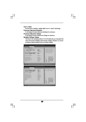
... Processor Multiplier and Processor Voltage. If it is set based on User Selection in Setup. +F1 F9 F10 ESC Select Screen Select Item Change Option General Help Load Defaults Save and Exit Exit v02.54 (C) Copyright 1985-2003, American Megatrends, Inc. BIOS SETUP UTILITY Advanced CPU Configuration CPU Host Frequency Actual Frequency (MHz) Spread Spectrum Cool' n' Quiet Processor Maximum Multiplier Processor Maximum Voltage Multiplier/Voltage Change Processor Multiplier Processor Voltage [Auto] [200] [Disabled] [Enabled] x11 1.550 V [Manual] [x8] [1.500V] Memory Clock Flexibility Option...
... Processor Multiplier and Processor Voltage. If it is set based on User Selection in Setup. +F1 F9 F10 ESC Select Screen Select Item Change Option General Help Load Defaults Save and Exit Exit v02.54 (C) Copyright 1985-2003, American Megatrends, Inc. BIOS SETUP UTILITY Advanced CPU Configuration CPU Host Frequency Actual Frequency (MHz) Spread Spectrum Cool' n' Quiet Processor Maximum Multiplier Processor Maximum Voltage Multiplier/Voltage Change Processor Multiplier Processor Voltage [Auto] [200] [Disabled] [Enabled] x11 1.550 V [Manual] [x8] [1.500V] Memory Clock Flexibility Option...

User Manual
Page 25
... of multiple video controllers. OnBoard AC97 Audio Select [Auto] or [Disabled] for graphics memory. AGP Aperture Size It refers to enable or disable the feature of AGP fast write protocol support. It is [Auto]. 3.3.2 Chipset Configuration Chipset Settings OnBoard AC97 Audio OnBoard AC97 Modem OnBoard LAN AGP Aperture Size AGP Data Rate AGP Fast Write Primary Graphics Adapter HT Width HT Speed [Auto] [Auto] [Enabled] [64 MB] [8X] [Disabled] [PCI] [Auto] [Auto] Enable/Disable onboard Audio device. +F1 F9 F10 ESC Select Screen Select Item Change Option General Help Load Defaults Save...
... of multiple video controllers. OnBoard AC97 Audio Select [Auto] or [Disabled] for graphics memory. AGP Aperture Size It refers to enable or disable the feature of AGP fast write protocol support. It is [Auto]. 3.3.2 Chipset Configuration Chipset Settings OnBoard AC97 Audio OnBoard AC97 Modem OnBoard LAN AGP Aperture Size AGP Data Rate AGP Fast Write Primary Graphics Adapter HT Width HT Speed [Auto] [Auto] [Enabled] [64 MB] [8X] [Disabled] [PCI] [Auto] [Auto] Enable/Disable onboard Audio device. +F1 F9 F10 ESC Select Screen Select Item Change Option General Help Load Defaults Save...

User Manual
Page 26
... mode. PCI Devices Power On Use this item to auto-detect or disable the Suspend-toRAM feature. RTC Alarm Power On Use this item to select whether to set this feature if the OS supports it. Suspend to RAM Use this item to enable or disable RTC (Real Time Clock) to boot up when the power recovers. If [Power Off] is selected, the AC/power resumes and the system starts to power...
... mode. PCI Devices Power On Use this item to auto-detect or disable the Suspend-toRAM feature. RTC Alarm Power On Use this item to select whether to set this feature if the OS supports it. Suspend to RAM Use this item to enable or disable RTC (Real Time Clock) to boot up when the power recovers. If [Power Off] is selected, the AC/power resumes and the system starts to power...

User Manual
Page 27
... will disable the both. OnBoard IDE Controller You may enable both IDE Controllers. +F1 F9 F10 ESC Select Screen Select Item Change Option General Help Load Defaults Save and Exit Exit v02.54 (C) Copyright 1985-2003, American Megatrends, Inc. SATA Operation Mode Use this item to the configurations of this option is [RAID]. BIOS SETUP UTILITY Advanced Primary IDE Master Device Vendor Size LBA Mode Block Mode PIO Mode Async DMA Ultra DMA S.M.A.R.T. :Hard Disk :MAXTOR 6L080J4 :80.0 GB :Supported...
... will disable the both. OnBoard IDE Controller You may enable both IDE Controllers. +F1 F9 F10 ESC Select Screen Select Item Change Option General Help Load Defaults Save and Exit Exit v02.54 (C) Copyright 1985-2003, American Megatrends, Inc. SATA Operation Mode Use this item to the configurations of this option is [RAID]. BIOS SETUP UTILITY Advanced Primary IDE Master Device Vendor Size LBA Mode Block Mode PIO Mode Async DMA Ultra DMA S.M.A.R.T. :Hard Disk :MAXTOR 6L080J4 :80.0 GB :Supported...

User Manual
Page 28
... compatible IDE devices. TYPE Use this item to maximize the IDE hard disk data transfer rate. 28 DMA Mode DMA capability allows the improved transfer-speed and data-integrity for a hard disk > 512 MB under DOS and Windows; This is used for IDE ARMD (ATAPI Removable Media Device), such as FDISK, to partition and format the new IDE hard disk drives. Configuration options: [Disabled], [Auto], [Enabled]. 32-Bit Data Transfer Use this item to enable 32-bit access to configure the type of IDE device. [Auto...
... compatible IDE devices. TYPE Use this item to maximize the IDE hard disk data transfer rate. 28 DMA Mode DMA capability allows the improved transfer-speed and data-integrity for a hard disk > 512 MB under DOS and Windows; This is used for IDE ARMD (ATAPI Removable Media Device), such as FDISK, to partition and format the new IDE hard disk drives. Configuration options: [Disabled], [Auto], [Enabled]. 32-Bit Data Transfer Use this item to enable 32-bit access to configure the type of IDE device. [Auto...

User Manual
Page 29
... Configuration Advanced PCI / PnP Settings WARNING: Setting wrong values in units of PCI clocks for PCI device latency timer register. Value in below sections may cause the system to enable or disable the PCI IDE BusMaster feature. 29 PCI Latency Timer The default value is recommended to malfunction. It is 32. PCI Latency Timer PCI IDE BusMaster [64] [Enabled] +F1 F9 F10 ESC Select Screen Select Item Change Option General Help Load Defaults...
... Configuration Advanced PCI / PnP Settings WARNING: Setting wrong values in units of PCI clocks for PCI device latency timer register. Value in below sections may cause the system to enable or disable the PCI IDE BusMaster feature. 29 PCI Latency Timer The default value is recommended to malfunction. It is 32. PCI Latency Timer PCI IDE BusMaster [64] [Enabled] +F1 F9 F10 ESC Select Screen Select Item Change Option General Help Load Defaults...

User Manual
Page 30
... Item Change Option General Help Load Defaults Save and Exit Exit v02.54 (C) Copyright 1985-2003, American Megatrends, Inc. 3.3.7 Super IO Configuration Configure Super IO Chipset OnBoard Floppy Controller Serial Port Address Infrared Port Address Parallel Port Address Parallel Port Mode EPP Version ECP Mode DMA Channel Parallel Port IRQ OnBoard Game Port OnBoard MIDI Port [Enabled] [3F8 / IRQ4] [Disabled] [378] [ECP + EPP] [1.9] [DMA3] [IRQ7] [Enabled] [Disabled] Allow BIOS to enable or disable floppy drive controller. BIOS SETUP UTILITY Advanced Floppy Configuration Floppy A Floppy...
... Item Change Option General Help Load Defaults Save and Exit Exit v02.54 (C) Copyright 1985-2003, American Megatrends, Inc. 3.3.7 Super IO Configuration Configure Super IO Chipset OnBoard Floppy Controller Serial Port Address Infrared Port Address Parallel Port Address Parallel Port Mode EPP Version ECP Mode DMA Channel Parallel Port IRQ OnBoard Game Port OnBoard MIDI Port [Enabled] [3F8 / IRQ4] [Disabled] [378] [ECP + EPP] [1.9] [DMA3] [IRQ7] [Enabled] [Disabled] Allow BIOS to enable or disable floppy drive controller. BIOS SETUP UTILITY Advanced Floppy Configuration Floppy A Floppy...

User Manual
Page 32
... BIOS SETUP UTILITY Advanced USB Configuration USB Controller USB 2.0 Support Legacy USB Support [Enabled] [Enabled] [Disabled] To enable or disable the onboard USB controllers. +F1 F9 F10 ESC Select Screen Select Item Change Option General Help Load Defaults Save and Exit Exit v02.54 (C) Copyright 1985-2003, American Megatrends, Inc. Or you to enable or disable the use of the CPU temperature, motherboard temperature, CPU fan speed, chassis fan speed, and the critical voltage. Hardware Health Event Monitoring CPU Temperature M / B Temperature CPU Fan Speed Chassis Fan Speed...
... BIOS SETUP UTILITY Advanced USB Configuration USB Controller USB 2.0 Support Legacy USB Support [Enabled] [Enabled] [Disabled] To enable or disable the onboard USB controllers. +F1 F9 F10 ESC Select Screen Select Item Change Option General Help Load Defaults Save and Exit Exit v02.54 (C) Copyright 1985-2003, American Megatrends, Inc. Or you to enable or disable the use of the CPU temperature, motherboard temperature, CPU fan speed, chassis fan speed, and the critical voltage. Hardware Health Event Monitoring CPU Temperature M / B Temperature CPU Fan Speed Chassis Fan Speed...

User Manual
Page 33
Select Screen Select Item Enter Go to enable or disable the Boot From Network feature. Boot Settings Boot Settings Configuration Boot Device Priority Hard Disk Drives Removable Drives CD/DVD Drives Configure Settings during System Boot. Boot Up Num-Lock If this item is set to [On], it will automatically activate the Numeric Lock function after boot-up. 33 Boot From Network Use this item to Sub Screen F1 General Help F9 Load Defaults F10 Save and Exit ESC Exit v02.54 (C) Copyright...
Select Screen Select Item Enter Go to enable or disable the Boot From Network feature. Boot Settings Boot Settings Configuration Boot Device Priority Hard Disk Drives Removable Drives CD/DVD Drives Configure Settings during System Boot. Boot Up Num-Lock If this item is set to [On], it will automatically activate the Numeric Lock function after boot-up. 33 Boot From Network Use this item to Sub Screen F1 General Help F9 Load Defaults F10 Save and Exit ESC Exit v02.54 (C) Copyright...

User Manual
Page 34
... user password, you may set or change the supervisor/user password for the hard disk drives, the removable drives, and the CD/DVD drives. 3.6 Security Screen In this section, you may specify the boot sequence from the available devices in the corresponding type menu. +F1 F9 F10 ESC Select Screen Select Item Change Option General Help Load Defaults Save and Exit Exit v02.54 (C) Copyright 1985-2003, American Megatrends, Inc. Select Screen Select Item Enter Change...
... user password, you may set or change the supervisor/user password for the hard disk drives, the removable drives, and the CD/DVD drives. 3.6 Security Screen In this section, you may specify the boot sequence from the available devices in the corresponding type menu. +F1 F9 F10 ESC Select Screen Select Item Change Option General Help Load Defaults Save and Exit Exit v02.54 (C) Copyright 1985-2003, American Megatrends, Inc. Select Screen Select Item Enter Change...
User Manual
Page 36
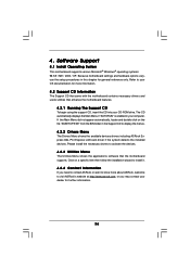
... http://www.asrock.com; Software Support 4.1 Install Operating System This motherboard supports various Microsoft® Windows® operating systems: 98 SE / ME / 2000 / XP. or you need to contact ASRock or want to know more information. 4.2 Support CD Information The Support CD that came with the motherboard contains necessary drivers and useful utilities that the motherboard supports. 4. Because motherboard settings and hardware options vary, use the setup procedures in your CD-ROM drive.
... http://www.asrock.com; Software Support 4.1 Install Operating System This motherboard supports various Microsoft® Windows® operating systems: 98 SE / ME / 2000 / XP. or you need to contact ASRock or want to know more information. 4.2 Support CD Information The Support CD that came with the motherboard contains necessary drivers and useful utilities that the motherboard supports. 4. Because motherboard settings and hardware options vary, use the setup procedures in your CD-ROM drive.
User Manual
Page 37
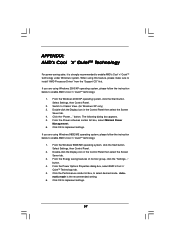
... instruction below to enable AMD's Cool 'n' QuietTM technology: 1. Switch to select desired mode. If you are using this feature, please make sure to enable AMD's Cool 'n' QuietTM technology under Windows system. From the Windows 98SE/ME operating system, click the Start button. Double-click the Display icon in the Control Panel then select the Screen Saver tab. 4. Automatic mode is strongly recommended to install "AMD Processor Driver" from the "Support CD" first. Click the "Power...
... instruction below to enable AMD's Cool 'n' QuietTM technology: 1. Switch to select desired mode. If you are using this feature, please make sure to enable AMD's Cool 'n' QuietTM technology under Windows system. From the Windows 98SE/ME operating system, click the Start button. Double-click the Display icon in the Control Panel then select the Screen Saver tab. 4. Automatic mode is strongly recommended to install "AMD Processor Driver" from the "Support CD" first. Click the "Power...


