User Manual
Page 3
... Advanced Menu 19 2. Contents 1 Introduction 4 1.1 Package Contents 4 1.2 Specifications 4 1.3 Motherboard Layout 6 1.4 ASRock I/O 7 TM ...2 Installation 8 2.1 Screw Holes 8 2.2 Pre-installation Precautions 8 2.3 CPU Installation 8 2.4 Installation of Heatsink and CPU fan 9 2.5 Installation of Memory Modules (DIMM 9 2.6 Expansion Slots 10 2.7 Jumpers Setup 11 2.8 Connectors 11 ...4.2.1 Running Support CD 18 4.2.2 Drivers Menu 18 4.2.3 Utilities Menu 18 4.2.4 ASRock "PC-DIY Live Demo" Program 18 4.2.5 Contact Information 18 Appendix 19 1. Boot Menu 23 5. Exit Menu 23 3
... Advanced Menu 19 2. Contents 1 Introduction 4 1.1 Package Contents 4 1.2 Specifications 4 1.3 Motherboard Layout 6 1.4 ASRock I/O 7 TM ...2 Installation 8 2.1 Screw Holes 8 2.2 Pre-installation Precautions 8 2.3 CPU Installation 8 2.4 Installation of Heatsink and CPU fan 9 2.5 Installation of Memory Modules (DIMM 9 2.6 Expansion Slots 10 2.7 Jumpers Setup 11 2.8 Connectors 11 ...4.2.1 Running Support CD 18 4.2.2 Drivers Menu 18 4.2.3 Utilities Menu 18 4.2.4 ASRock "PC-DIY Live Demo" Program 18 4.2.5 Contact Information 18 Appendix 19 1. Boot Menu 23 5. Exit Menu 23 3
User Manual
Page 4
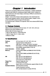
...'97 Audio Speed: 802.3u (10/100 Ethernet), supports Wake-On-LAN CPU temperature sensing; For advanced users' reference, the Appendix offers more advanced BIOS Setup information. 1.1 Package Contents ASRock K7VT2 motherboard (ATX form factor: 12" x 9.6", 30.5 x 24.4 cm) ASRock K7VT2 Quick Installation Guide ASRock AMD-VIA Series Support CD 1 cable for IDE devices (1 x ATA 66...
...'97 Audio Speed: 802.3u (10/100 Ethernet), supports Wake-On-LAN CPU temperature sensing; For advanced users' reference, the Appendix offers more advanced BIOS Setup information. 1.1 Package Contents ASRock K7VT2 motherboard (ATX form factor: 12" x 9.6", 30.5 x 24.4 cm) ASRock K7VT2 Quick Installation Guide ASRock AMD-VIA Series Support CD 1 cable for IDE devices (1 x ATA 66...
User Manual
Page 5
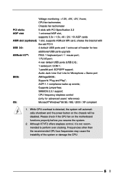
CPU frequency stepless control (only for two additional USB ports upgrade ASRock I/OTM: PS/2: 1 keyboard port / 1 mouse port; 1 RJ 45 port; 4 rear default USB ports (USB 2.0); 1 serial port: COM 1; 1 parallel port: ECP/EPP support; Supports "Plug and Play"; SMBIOS 2.3.1 support; Although K7VT2 offers stepless control, it is detected, the system will automatically shutdown and...
CPU frequency stepless control (only for two additional USB ports upgrade ASRock I/OTM: PS/2: 1 keyboard port / 1 mouse port; 1 RJ 45 port; 4 rear default USB ports (USB 2.0); 1 serial port: COM 1; 1 parallel port: ECP/EPP support; Supports "Plug and Play"; SMBIOS 2.3.1 support; Although K7VT2 offers stepless control, it is detected, the system will automatically shutdown and...
User Manual
Page 8
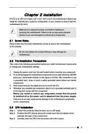
...lever up to the motherboard, peripherals, and/or components. 2.3 CPU Installation Step 1. Step 2. Do not over-tighten the screws! Position the CPU directly above the socket such that comes with the component. Chapter 2 Installation K7VT2 is detached from the wall socket before installing or removing the ... switched off or the power cord is an ATX form factor (12" x 9.6", 30.5 x 24.4 cm) motherboard. Carefully insert the CPU into it on the carpet or the like. Before you install or remove any motherboard settings. 1. Doing so may cause physical injuries to unplug...
...lever up to the motherboard, peripherals, and/or components. 2.3 CPU Installation Step 1. Step 2. Do not over-tighten the screws! Position the CPU directly above the socket such that comes with the component. Chapter 2 Installation K7VT2 is detached from the wall socket before installing or removing the ... switched off or the power cord is an ATX form factor (12" x 9.6", 30.5 x 24.4 cm) motherboard. Carefully insert the CPU into it on the carpet or the like. Before you install or remove any motherboard settings. 1. Doing so may cause physical injuries to unplug...
User Manual
Page 9
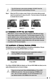
...Data Rate) SDRAM DIMM has 184 pins. Make sure that it is in place, press it is also needed to secure the CPU. Step 1 Step 2, 3 Step 4 2.4 Installation of CPU Fan and Heatsink AMD AhtlonTM / DuronTM family CPUs with each other. Only use two different brands of the DIMMs at the same...the pins. Also, for proper operation, it firmly on the side tab to indicate that the CPU and the heatsink are securely fastened and in one time. Step 4. Thermal grease between the CPU and the heatsink is not recommended to disconnect power supply before adding or removing DIMMs or the ...
...Data Rate) SDRAM DIMM has 184 pins. Make sure that it is in place, press it is also needed to secure the CPU. Step 1 Step 2, 3 Step 4 2.4 Installation of CPU Fan and Heatsink AMD AhtlonTM / DuronTM family CPUs with each other. Only use two different brands of the DIMMs at the same...the pins. Also, for proper operation, it firmly on the side tab to indicate that the CPU and the heatsink are securely fastened and in one time. Step 4. Thermal grease between the CPU and the heatsink is not recommended to disconnect power supply before adding or removing DIMMs or the ...
User Manual
Page 11
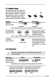
... 1_2 2_3 Short pin2, pin3 to enable (see p.6 item 17) solder points 2.8 Connectors Disconnect the power cord, then short the solder points to set the CPU front side bus frequency. When the jumper cap is placed on the pins, the jumper is "SHORT". The illustration shows a 3-pin jumper whose pin1 and...
... 1_2 2_3 Short pin2, pin3 to enable (see p.6 item 17) solder points 2.8 Connectors Disconnect the power cord, then short the solder points to set the CPU front side bus frequency. When the jumper cap is placed on the pins, the jumper is "SHORT". The illustration shows a 3-pin jumper whose pin1 and...
User Manual
Page 13
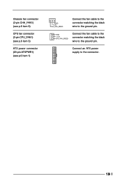
GND +12V CPU_FAN_SPEED Connect the fan cable to the connector matching the black wire to the connector. 13 Connect an ATX power supply to the ground pin. Chassis fan connector (3-pin CHA_FAN1) (see p.6 item 9) CPU fan connector (3-pin CPU_FAN1) (see p.6 item 3) ATX power connector (20-pin ATXPWR1) (see p.6 item 1) GND +12V CHA_FAN_SPEED Connect the fan cable to the connector matching the black wire to the ground pin.
GND +12V CPU_FAN_SPEED Connect the fan cable to the connector matching the black wire to the connector. 13 Connect an ATX power supply to the ground pin. Chassis fan connector (3-pin CHA_FAN1) (see p.6 item 9) CPU fan connector (3-pin CPU_FAN1) (see p.6 item 3) ATX power connector (20-pin ATXPWR1) (see p.6 item 1) GND +12V CHA_FAN_SPEED Connect the fan cable to the connector matching the black wire to the ground pin.
User Manual
Page 19
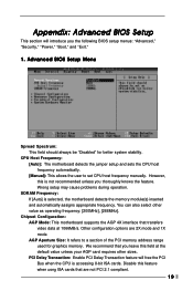
... the default value unless your AGP card requires other value as operating frequency: [200MHz], [266MHz]. AGP Aperture Size: It refers to set CPU host frequency manually. SDRAM Frequency: If [Auto] is accessing 8-bit ISA cards. Disable this is not recommended unless you thoroughly knows the... feature. Appendix: Advanced BIOS Setup This section will free the PCI Bus when the CPU is selected, the motherboard detects the memory module(s) inserted and automatically assigns appropriate frequency. However, this feature when usng ISA cards ...
... the default value unless your AGP card requires other value as operating frequency: [200MHz], [266MHz]. AGP Aperture Size: It refers to set CPU host frequency manually. SDRAM Frequency: If [Auto] is accessing 8-bit ISA cards. Disable this is not recommended unless you thoroughly knows the... feature. Appendix: Advanced BIOS Setup This section will free the PCI Bus when the CPU is selected, the motherboard detects the memory module(s) inserted and automatically assigns appropriate frequency. However, this feature when usng ISA cards ...
User Manual
Page 21
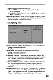
... current password first in order to set . If you already have a password, you must enter your system. Password Check: Select the check points for CPU temperature, Motherboard temperature, CPU fan speed, and critical voltage. 2. User Password: This field shows the status of the User Password. [Clear]: No password has been set. [Set...
... current password first in order to set . If you already have a password, you must enter your system. Password Check: Select the check points for CPU temperature, Motherboard temperature, CPU fan speed, and critical voltage. 2. User Password: This field shows the status of the User Password. [Clear]: No password has been set. [Set...
User Manual
Page 23
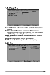
4. Boot Device Priority: This allows you to OS/2 operating system. Boot to OS/2: This enables boot up . Boot Up Num-Lock: This automatically activates the Numeric Lock function after boot up to set the boot device priority. 5. Exit Menu 23 If this screen is disabled, only ASRock logo is shown during Power-On-Self-Test (POST) routine. Boot Setup Menu Quick Boot Mode: This mode speeds up the boot-up process. Boot-time Diagnostic Screen: This screen shows CPU and hardware information during the boot up routine by skipping memory retestings.
4. Boot Device Priority: This allows you to OS/2 operating system. Boot to OS/2: This enables boot up . Boot Up Num-Lock: This automatically activates the Numeric Lock function after boot up to set the boot device priority. 5. Exit Menu 23 If this screen is disabled, only ASRock logo is shown during Power-On-Self-Test (POST) routine. Boot Setup Menu Quick Boot Mode: This mode speeds up the boot-up process. Boot-time Diagnostic Screen: This screen shows CPU and hardware information during the boot up routine by skipping memory retestings.


