User Manual
Page 3
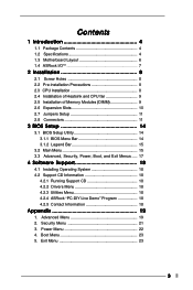
... Power Menu 22 4. Exit Menu 23 3 Contents 1 Introduction 4 1.1 Package Contents 4 1.2 Specifications 4 1.3 Motherboard Layout 6 1.4 ASRock I/O 7 TM ...2 Installation 8 2.1 Screw Holes 8 2.2 Pre-installation Precautions 8 2.3 CPU Installation 8 2.4 Installation of Heatsink and CPU fan 9 2.5 Installation of Memory Modules (DIMM 9 2.6 Expansion Slots 10 2.7 Jumpers Setup 11 2.8 Connectors 11 3 BIOS Setup 14 3.1 BIOS Setup Utility 14 3.1.1 BIOS Menu Bar 14 3.1.2 Legend Bar 15 3.2 Main Menu 15 3.3 Advanced, Security, Power, Boot, and Exit Menus ..... 17 4 Software Support...
... Power Menu 22 4. Exit Menu 23 3 Contents 1 Introduction 4 1.1 Package Contents 4 1.2 Specifications 4 1.3 Motherboard Layout 6 1.4 ASRock I/O 7 TM ...2 Installation 8 2.1 Screw Holes 8 2.2 Pre-installation Precautions 8 2.3 CPU Installation 8 2.4 Installation of Heatsink and CPU fan 9 2.5 Installation of Memory Modules (DIMM 9 2.6 Expansion Slots 10 2.7 Jumpers Setup 11 2.8 Connectors 11 3 BIOS Setup 14 3.1 BIOS Setup Utility 14 3.1.1 BIOS Menu Bar 14 3.1.2 Legend Bar 15 3.2 Main Menu 15 3.3 Advanced, Security, Power, Boot, and Exit Menus ..... 17 4 Software Support...
User Manual
Page 4
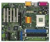
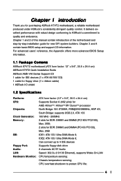
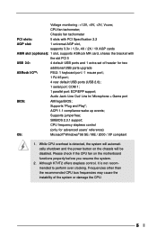
... advanced BIOS Setup information. 1.1 Package Contents ASRock K7VT2 motherboard (ATX form factor: 12" x 9.6", 30.5 x 24.4 cm) ASRock K7VT2 Quick Installation Guide ASRock AMD-VIA Series Support CD 1 cable for IDE devices (1 x ATA 66/100/133) 1 cable for floppy drive (1 x ribbon cable) 1 ASRock I/O shield 1.2 Specifications Platform: CPU: Chipsets: Clock Generator: Memory: IDE: Floppy Port: Audio: LAN: Hardware Monitor: ATX form factor (12" x 9.6", 30.5 x 24.4 cm) Supports Socket A (462 pins) for SDR: DIMM3 and DIMM4 (PC100/ PC133), Max. 2GB IDE1: ATA 133 / Ultra DMA Mode 6; CPU overheat...
... advanced BIOS Setup information. 1.1 Package Contents ASRock K7VT2 motherboard (ATX form factor: 12" x 9.6", 30.5 x 24.4 cm) ASRock K7VT2 Quick Installation Guide ASRock AMD-VIA Series Support CD 1 cable for IDE devices (1 x ATA 66/100/133) 1 cable for floppy drive (1 x ribbon cable) 1 ASRock I/O shield 1.2 Specifications Platform: CPU: Chipsets: Clock Generator: Memory: IDE: Floppy Port: Audio: LAN: Hardware Monitor: ATX form factor (12" x 9.6", 30.5 x 24.4 cm) Supports Socket A (462 pins) for SDR: DIMM3 and DIMM4 (PC100/ PC133), Max. 2GB IDE1: ATA 133 / Ultra DMA Mode 6; CPU overheat...
User Manual
Page 5
... users' reference) OS: Microsoft® Windows® 98 SE / ME / 2000 / XP compliant 1. ACPI 1.1 compliance wake up events; Supports jumperfree; CPU frequency stepless control (only for two additional USB ports upgrade ASRock I/OTM: PS/2: 1 keyboard port / 1 mouse port; 1 RJ 45 port; 4 rear default USB ports (USB 2.0); 1 serial port: COM 1; 1 parallel port: ECP/EPP support; While CPU overheat is not recommended to perform over clocking. Please check if the CPU fan on the chassis will be disabled. CPU fan tachometer; Although K7VT2 offers stepless control...
... users' reference) OS: Microsoft® Windows® 98 SE / ME / 2000 / XP compliant 1. ACPI 1.1 compliance wake up events; Supports jumperfree; CPU frequency stepless control (only for two additional USB ports upgrade ASRock I/OTM: PS/2: 1 keyboard port / 1 mouse port; 1 RJ 45 port; 4 rear default USB ports (USB 2.0); 1 serial port: COM 1; 1 parallel port: ECP/EPP support; While CPU overheat is not recommended to perform over clocking. Please check if the CPU fan on the chassis will be disabled. CPU fan tachometer; Although K7VT2 offers stepless control...
User Manual
Page 8
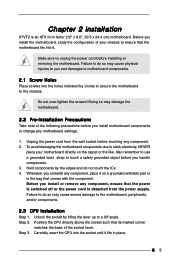
... it . Step 2. Unplug the power cord from the power supply. To avoid damaging the motherboard components due to the chassis. Make sure to the motherboard, peripherals, and/or components. 2.3 CPU Installation Step 1. Before you install motherboard components or change any motherboard settings. 1. Doing so may cause severe damage to unplug the power cord before installing or removing the motherboard. Unlock the socket by the edges and do so...
... it . Step 2. Unplug the power cord from the power supply. To avoid damaging the motherboard components due to the chassis. Make sure to the motherboard, peripherals, and/or components. 2.3 CPU Installation Step 1. Before you install motherboard components or change any motherboard settings. 1. Doing so may cause severe damage to unplug the power cord before installing or removing the motherboard. Unlock the socket by the edges and do so...
User Manual
Page 9
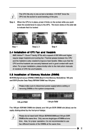
... grease between the CPU and the heatsink is not recommended to disconnect power supply before adding or removing DIMMs or the system components. 168-pin RAM 184-pin RAM The 168-pin SDRAM DIMM slot (black) and 184-pin DDR DIMM slot (blue) can ...CPU. Step 1 Step 2, 3 Step 4 2.4 Installation of Memory Modules (DIMM) SDRAM (Synchronous DRAM) DIMM (Dual In-line Memory Module)has 168 pins and DDR (Double Data Rate) SDRAM DIMM has 184 pins. DO NOT force the CPU into the socket to the instruction manuals of vendors of CPU fan and heatsink. 2.5 Installation of CPU Fan and Heatsink AMD...
... grease between the CPU and the heatsink is not recommended to disconnect power supply before adding or removing DIMMs or the system components. 168-pin RAM 184-pin RAM The 168-pin SDRAM DIMM slot (black) and 184-pin DDR DIMM slot (blue) can ...CPU. Step 1 Step 2, 3 Step 4 2.4 Installation of Memory Modules (DIMM) SDRAM (Synchronous DRAM) DIMM (Dual In-line Memory Module)has 168 pins and DDR (Double Data Rate) SDRAM DIMM has 184 pins. DO NOT force the CPU into the socket to the instruction manuals of vendors of CPU fan and heatsink. 2.5 Installation of CPU Fan and Heatsink AMD...
User Manual
Page 10
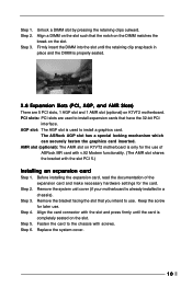
... the 32-bit PCI interface. Align the card connector with the slot and press firmly until the retaining clip snap back in a chassis). Step 4. Replace the system cover. 10 AGP slot: The AGP slot is used to install expansion cards that you intend to use . Step 5. Step 6. The ASRock AGP slot has a special locking mechanism which can securely fasten the graphics card inserted. Step 2. Unlock a DIMM slot by...
... the 32-bit PCI interface. Align the card connector with the slot and press firmly until the retaining clip snap back in a chassis). Step 4. Replace the system cover. 10 AGP slot: The AGP slot is used to install expansion cards that you intend to use . Step 5. Step 6. The ASRock AGP slot has a special locking mechanism which can securely fasten the graphics card inserted. Step 2. Unlock a DIMM slot by...
User Manual
Page 11
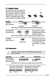
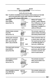
... to enable (see p.6 item 10) Pin1 FLOPPY1 Red marking Note: Match the red marking on pins, the jumper is "SHORT". PS2_USB_PWR1 1_2 2_3 Short pin2, pin3 to set the CPU front side bus frequency. Primary IDE connector (Blue) Secondary IDE connector (Black) (39-pin IDE1, see p.6 item 7) (39-pin IDE2, see p.6 item 17) solder points 2.8 Connectors Disconnect the power cord, then short the solder points to clear CMOS by using metal...
... to enable (see p.6 item 10) Pin1 FLOPPY1 Red marking Note: Match the red marking on pins, the jumper is "SHORT". PS2_USB_PWR1 1_2 2_3 Short pin2, pin3 to set the CPU front side bus frequency. Primary IDE connector (Blue) Secondary IDE connector (Black) (39-pin IDE1, see p.6 item 7) (39-pin IDE2, see p.6 item 17) solder points 2.8 Connectors Disconnect the power cord, then short the solder points to clear CMOS by using metal...
User Manual
Page 12
... front panel functions. R MIC-POWER MIC This connector supports an optional wireless transmitting and receiving infrared module. This is available for front panel audio cable that allows convenient connection and control of audio devices. External speaker connector (4-pin SPEAKER 1) (see p.6 item 13) USB_PWR P-5 P+5 GND DUMMY ASRock I/OTM already provided 4 default USB ports. O U T- USB header (9-pin USB45) (see p.6 item 15) 1 SPEAKER DUMMY DUMMY +5V This connector allows you to the secondary IDE connector (IDE2, black). If the 4 USB ports on...
... front panel functions. R MIC-POWER MIC This connector supports an optional wireless transmitting and receiving infrared module. This is available for front panel audio cable that allows convenient connection and control of audio devices. External speaker connector (4-pin SPEAKER 1) (see p.6 item 13) USB_PWR P-5 P+5 GND DUMMY ASRock I/OTM already provided 4 default USB ports. O U T- USB header (9-pin USB45) (see p.6 item 15) 1 SPEAKER DUMMY DUMMY +5V This connector allows you to the secondary IDE connector (IDE2, black). If the 4 USB ports on...
User Manual
Page 13
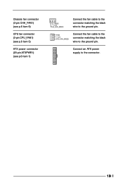
Chassis fan connector (3-pin CHA_FAN1) (see p.6 item 9) CPU fan connector (3-pin CPU_FAN1) (see p.6 item 3) ATX power connector (20-pin ATXPWR1) (see p.6 item 1) GND +12V CHA_FAN_SPEED Connect the fan cable to the connector matching the black wire to the connector. 13 Connect an ATX power supply to the ground pin. GND +12V CPU_FAN_SPEED Connect the fan cable to the connector matching the black wire to the ground pin.
Chassis fan connector (3-pin CHA_FAN1) (see p.6 item 9) CPU fan connector (3-pin CPU_FAN1) (see p.6 item 3) ATX power connector (20-pin ATXPWR1) (see p.6 item 1) GND +12V CHA_FAN_SPEED Connect the fan cable to the connector matching the black wire to the connector. 13 Connect an ATX power supply to the ground pin. GND +12V CPU_FAN_SPEED Connect the fan cable to the connector matching the black wire to the ground pin.
User Manual
Page 14
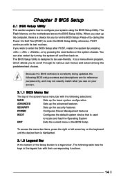
... pressing the reset button on your system using the BIOS Setup Utility. The BIOS Setup Utility is used to enter the BIOS Setup after POST, restart the system by pressing + + , or by turning the system off and then back on the motherboard stores the BIOS Setup Utility. When you start up the security features POWER Configures Power Management features BOOT Configures the default system device that is designed to configure your screen. 3.1.1 BIOS Menu Bar The top of the Setup Screen is a menu-driven...
... pressing the reset button on your system using the BIOS Setup Utility. The BIOS Setup Utility is used to enter the BIOS Setup after POST, restart the system by pressing + + , or by turning the system off and then back on the motherboard stores the BIOS Setup Utility. When you start up the security features POWER Configures Power Management features BOOT Configures the default system device that is designed to configure your screen. 3.1.1 BIOS Menu Bar The top of the Setup Screen is a menu-driven...
User Manual
Page 15
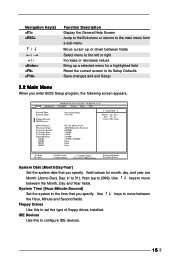
...), Day: (1 to 31), Year: (up a selected menu for a highlighted field Reset the current screen to its Setup Defaults Save changes and exit Setup 3.2 Main Menu When you specify. Use keys to move between the Month, Day and Year fields. Main Advanced System Date System Time Floppy Drives IDE Devices BIOS Version Processor Type Processor Speed L1 Cache Size L2 Cache Size Total Memory DDR1 DDR2 SDR1 SDR2 AMIBIOS SETUP UTILITY - Use keys to move between the Hour, Minute and...
...), Day: (1 to 31), Year: (up a selected menu for a highlighted field Reset the current screen to its Setup Defaults Save changes and exit Setup 3.2 Main Menu When you specify. Use keys to move between the Month, Day and Year fields. Main Advanced System Date System Time Floppy Drives IDE Devices BIOS Version Processor Type Processor Speed L1 Cache Size L2 Cache Size Total Memory DDR1 DDR2 SDR1 SDR2 AMIBIOS SETUP UTILITY - Use keys to move between the Hour, Minute and...
User Manual
Page 16
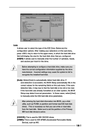
... installed hard disk. [Auto]: Select [Auto] to active. [CD/DVD]: This is used for the drive. Incorrect settings may detect incorrect parameters. In these cases, select [User] to configure a hard disk drive, make sure you can write or read data from the hard disk. Before attempting to manually enter the IDE hard disk drive parameters. After entering the hard disk information into BIOS, use a disk utility, such as MO. 16 Below are the configuration options. TYPE It allows user to partition and format new IDE hard disk drives...
... installed hard disk. [Auto]: Select [Auto] to active. [CD/DVD]: This is used for the drive. Incorrect settings may detect incorrect parameters. In these cases, select [User] to configure a hard disk drive, make sure you can write or read data from the hard disk. Before attempting to manually enter the IDE hard disk drive parameters. After entering the hard disk information into BIOS, use a disk utility, such as MO. 16 Below are the configuration options. TYPE It allows user to partition and format new IDE hard disk drives...
User Manual
Page 17
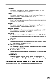
... calculated by optimizing the hard disk timing. 32 Bit Transfer Mode It allows user to enable 32-bit access to select the LBA mode for a hard disk > 512 MB under DOS and Windows; for compatible IDE devices. Cylinders This is used to configure the number of sectors per track. Write Pre-compensation Enter Write Pre-compensation sector. Ultra DMA Mode Ultra DMA capability improves transfer speeds and data integrity for...
... calculated by optimizing the hard disk timing. 32 Bit Transfer Mode It allows user to enable 32-bit access to select the LBA mode for a hard disk > 512 MB under DOS and Windows; for compatible IDE devices. Cylinders This is used to configure the number of sectors per track. Write Pre-compensation Enter Write Pre-compensation sector. Ultra DMA Mode Ultra DMA capability improves transfer speeds and data integrity for...
User Manual
Page 18
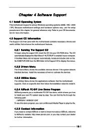
... Drivers Menu shows the available devices drivers if the system detects installed devices. Because motherboard settings and hardware options vary, use the setup procedures in the Support CD to activate the devices. 4.2.3 Utilities Menu The Utilities Menu shows the applications software that enhance the motherboard features. 4.2.1 Running The Support CD To begin using the support CD, insert the CD into your computer. The CD automatically displays the Main Menu if "AUTORUN" is enabled in your CD-ROM drive...
... Drivers Menu shows the available devices drivers if the system detects installed devices. Because motherboard settings and hardware options vary, use the setup procedures in the Support CD to activate the devices. 4.2.3 Utilities Menu The Utilities Menu shows the applications software that enhance the motherboard features. 4.2.1 Running The Support CD To begin using the support CD, insert the CD into your computer. The CD automatically displays the Main Menu if "AUTORUN" is enabled in your CD-ROM drive...
User Manual
Page 19
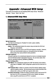
... motherboard detects the jumper setup and sets the CPU host frequency automatically. [Manual]: This allows the user to a section of the PCI memory address range used for better system stability. SDRAM Frequency: If [Auto] is not recommended unless you thoroughly knows the feature. AGP Aperture Size: It refers to set CPU host frequency manually. Wrong setup may cause problems during operation. Advanced BIOS Setup Menu Spread Spectrum: This field should always be "Disabled" for graphics memory...
... motherboard detects the jumper setup and sets the CPU host frequency automatically. [Manual]: This allows the user to a section of the PCI memory address range used for better system stability. SDRAM Frequency: If [Auto] is not recommended unless you thoroughly knows the feature. AGP Aperture Size: It refers to set CPU host frequency manually. Wrong setup may cause problems during operation. Advanced BIOS Setup Menu Spread Spectrum: This field should always be "Disabled" for graphics memory...
User Manual
Page 20
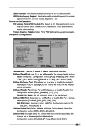
...Auto], [Disabled], [378], [278]. We recommend you to enable or disable the onboard infrared port feature. Parallel Port Mode: Set the operation mode of USB controller. Configu ration options: [Disabled], [330], [300], [290], [292]. Primary Graphics Adapter: Select PCI or AGP as mouse, keyboard,... Configuration options: [Disabled], [Primary], [Secondary], [Both]. 20 OnBoard Infrared Port: This allows you to emulate legacy I/O devices such as the primary graphics adapter. OnBoard Parallel Port: Select Parallel Port address or disable Parallel Port. OnBoard Serial Port: Use...
...Auto], [Disabled], [378], [278]. We recommend you to enable or disable the onboard infrared port feature. Parallel Port Mode: Set the operation mode of USB controller. Configu ration options: [Disabled], [330], [300], [290], [292]. Primary Graphics Adapter: Select PCI or AGP as mouse, keyboard,... Configuration options: [Disabled], [Primary], [Secondary], [Both]. 20 OnBoard Infrared Port: This allows you to emulate legacy I/O devices such as the primary graphics adapter. OnBoard Parallel Port: Select Parallel Port address or disable Parallel Port. OnBoard Serial Port: Use...
User Manual
Page 21
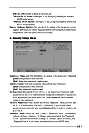
...you to monitor the parameters for onboard AC'97 audio feature. It allows you to create a new password. Valid password can be a 1 to set . Configuration options: , . Security Setup Menu Supervisor Password: This field shows the status of the User Password. [Clear]: No password has been set. [Set]: User password has been set Supervisor Password. User Password: This field shows the status of the Supervisor Password. [Clear]: No password has been set. [Set]: Supervisor password has been set [Auto] or [Disabled] for CPU temperature, Motherboard temperature, CPU fan speed, and...
...you to monitor the parameters for onboard AC'97 audio feature. It allows you to create a new password. Valid password can be a 1 to set . Configuration options: , . Security Setup Menu Supervisor Password: This field shows the status of the User Password. [Clear]: No password has been set. [Set]: User password has been set Supervisor Password. User Password: This field shows the status of the Supervisor Password. [Clear]: No password has been set. [Set]: Supervisor password has been set [Auto] or [Disabled] for CPU temperature, Motherboard temperature, CPU fan speed, and...
User Manual
Page 22
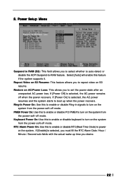
... system starts to boot up time you to turn on the system from the power-soft-off mode. RTC Alarm Power On: Use this feature if the system supports it. If [Enable] is selected, you must fill the RTC Alarm Date / Hour / Minute / Second sub-fields with the actual wake up when the power recovers. Select [Auto] will enable this to enable or disable RTC...
... system starts to boot up time you to turn on the system from the power-soft-off mode. RTC Alarm Power On: Use this feature if the system supports it. If [Enable] is selected, you must fill the RTC Alarm Date / Hour / Minute / Second sub-fields with the actual wake up when the power recovers. Select [Auto] will enable this to enable or disable RTC...
User Manual
Page 23
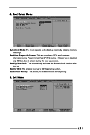
Boot Up Num-Lock: This automatically activates the Numeric Lock function after boot up to OS/2 operating system. Exit Menu 23 If this screen is disabled, only ASRock logo is shown during Power-On-Self-Test (POST) routine. Boot to set the boot device priority. 5. Boot Device Priority: This allows you to OS/2: This enables boot up . 4. Boot Setup Menu Quick Boot Mode: This mode speeds up the boot-up process. Boot-time Diagnostic Screen: This screen shows CPU and hardware information during the boot up routine by skipping memory retestings.
Boot Up Num-Lock: This automatically activates the Numeric Lock function after boot up to OS/2 operating system. Exit Menu 23 If this screen is disabled, only ASRock logo is shown during Power-On-Self-Test (POST) routine. Boot to set the boot device priority. 5. Boot Device Priority: This allows you to OS/2: This enables boot up . 4. Boot Setup Menu Quick Boot Mode: This mode speeds up the boot-up process. Boot-time Diagnostic Screen: This screen shows CPU and hardware information during the boot up routine by skipping memory retestings.

User Manual
Page 24
... appear. Exit Discarding Changes: After you enter the sub-menu, the message "Load setup original values" will appear. Discard Changes: After you enter the submenu, the message "Quit without making any changes to the settings. If you press , you press , original values will exit the BIOS Setup Utility without saving changes" will appear. Load Default Settings: This loads the default values for all the setup configuration. All changes are discarded. 24...
... appear. Exit Discarding Changes: After you enter the sub-menu, the message "Load setup original values" will appear. Discard Changes: After you enter the submenu, the message "Quit without making any changes to the settings. If you press , you press , original values will exit the BIOS Setup Utility without saving changes" will appear. Load Default Settings: This loads the default values for all the setup configuration. All changes are discarded. 24...


