
User Manual
Page 3
... 1 Introduction 4 1.1 Package Contents 4 1.2 Specifications 5 1.3 Motherboard Layout 7 1.4 ASRock I/O PlusTM 8 2 Installation 9 2.1 Screw Holes 9 2.2 Pre-installation Precautions 9 2.3 CPU Installation 10 2.4 Installation of CPU Fan and Heatsink 10 2.5 Installation of Memory Modules (DIMM 11 2.6 Expansion Slots (... Power, Boot, and Exit Menus ..... 22 4 Software Support 23 4.1 Install Operating System 23 4.2 Support CD Information 23 4.2.1 Running Support CD 23 4.2.2 Drivers Menu 23 4.2.3 Utilities Menu 23 4.2.4 ASRock "PC-DIY Live Demo" Program 23 4.2.5 Contact Information 23...
... 1 Introduction 4 1.1 Package Contents 4 1.2 Specifications 5 1.3 Motherboard Layout 7 1.4 ASRock I/O PlusTM 8 2 Installation 9 2.1 Screw Holes 9 2.2 Pre-installation Precautions 9 2.3 CPU Installation 10 2.4 Installation of CPU Fan and Heatsink 10 2.5 Installation of Memory Modules (DIMM 11 2.6 Expansion Slots (... Power, Boot, and Exit Menus ..... 22 4 Software Support 23 4.1 Install Operating System 23 4.2 Support CD Information 23 4.2.1 Running Support CD 23 4.2.2 Drivers Menu 23 4.2.3 Utilities Menu 23 4.2.4 ASRock "PC-DIY Live Demo" Program 23 4.2.5 Contact Information 23...

User Manual
Page 4
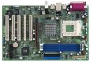
....0-in x 7.5-in, 30.5 cm x 19.1 cm) ASRock K7S8XE+ Quick Installation Guide ASRock K7S8XE+ Support CD One 80-conductor Ultra ATA 66/100/133 IDE Ribbon Cable One Ribbon Cable for purchasing ASRock K7S8XE+ motherboard, a reliable motherboard produced under ASRock's consistently stringent quality control. You may find the latest memory and CPU support lists on ASRock website without notice. Chapter 3 and 4 contain...
....0-in x 7.5-in, 30.5 cm x 19.1 cm) ASRock K7S8XE+ Quick Installation Guide ASRock K7S8XE+ Support CD One 80-conductor Ultra ATA 66/100/133 IDE Ribbon Cable One Ribbon Cable for purchasing ASRock K7S8XE+ motherboard, a reliable motherboard produced under ASRock's consistently stringent quality control. You may find the latest memory and CPU support lists on ASRock website without notice. Chapter 3 and 4 contain...
User Manual
Page 5
...; PC3200 (DDR400) for 2 DDR DIMM slots, Max. 2GB; IDE2: ATA 133 / Ultra DMA Mode 6; CPU overheat shutdown to protect CPU life (ASRock U-COP)(see CAUTION 4) ASRock I/O PlusTM: 1 PS/2 keyboard port, 1 PS/2 mouse port; 1 serial port: COM1; 1 parallel port: ECP/EPP support; 1 RJ 45 port; 6 default USB 2.0 ports; Chassis temperature sensing; Voltage monitoring: +12V, +5V, +3V...
...; PC3200 (DDR400) for 2 DDR DIMM slots, Max. 2GB; IDE2: ATA 133 / Ultra DMA Mode 6; CPU overheat shutdown to protect CPU life (ASRock U-COP)(see CAUTION 4) ASRock I/O PlusTM: 1 PS/2 keyboard port, 1 PS/2 mouse port; 1 serial port: COM1; 1 parallel port: ECP/EPP support; 1 RJ 45 port; 6 default USB 2.0 ports; Chassis temperature sensing; Voltage monitoring: +12V, +5V, +3V...
User Manual
Page 6
... this motherboard is determined by the jumpersetting. Although K7S8XE+ offers stepless control, it will not support DDR200; BIOS: OS: AMI legal BIOS; ACPI 1.1 compliance wake up events; CPU at FSB 200MHz mode, it is detected, the system will not support DDR200 / DDR266 2. Please check if the CPU fan on the motherboard functions properly before you...
... this motherboard is determined by the jumpersetting. Although K7S8XE+ offers stepless control, it will not support DDR200; BIOS: OS: AMI legal BIOS; ACPI 1.1 compliance wake up events; CPU at FSB 200MHz mode, it is detected, the system will not support DDR200 / DDR266 2. Please check if the CPU fan on the motherboard functions properly before you...

User Manual
Page 14
... (External frequency) = 1666MHz FID jumpers setting: 1 FID0 1 FID1 1 FID2 1 FID3 1 FID4 The jumper caps are only for normal usage. Please understand that ASRock does not guarantee and support the adjustment of CPU. FID Jumpers (FID0, FID1, FID2, FID3, FID4) (see p.7 item 33) 1 FID0 1 FID1 1 FID2 1 FID3 1 FID4 Note: The set of FID jumpers...
... (External frequency) = 1666MHz FID jumpers setting: 1 FID0 1 FID1 1 FID2 1 FID3 1 FID4 The jumper caps are only for normal usage. Please understand that ASRock does not guarantee and support the adjustment of CPU. FID Jumpers (FID0, FID1, FID2, FID3, FID4) (see p.7 item 33) 1 FID0 1 FID1 1 FID2 1 FID3 1 FID4 Note: The set of FID jumpers...

User Manual
Page 25
...Latency Over Vcore Voltage 64M Enabled Enabled Enabled Auto Disabled to adjust the means of memory accessing. USB 2.0 Support: Use this to enable or disable USB 2.0 support USB Device Legacy Support: Use this to enable "Over Vcore Voltage" feature. The default value is not recommended to enable or... disable the use of mapped memory for graphics memory. USB Controller: Use this to enable or disable the support to leave this item will increase the CPU Vcore voltage around 5%. Over Vcore Voltage: Enable this field at the default value unless the installed AGP card's ...
...Latency Over Vcore Voltage 64M Enabled Enabled Enabled Auto Disabled to adjust the means of memory accessing. USB 2.0 Support: Use this to enable or disable USB 2.0 support USB Device Legacy Support: Use this to enable "Over Vcore Voltage" feature. The default value is not recommended to enable or... disable the use of mapped memory for graphics memory. USB Controller: Use this to enable or disable the support to leave this item will increase the CPU Vcore voltage around 5%. Over Vcore Voltage: Enable this field at the default value unless the installed AGP card's ...

User Manual
Page 3
... 4 1.1 Package Contents 4 1.2 Specifications 5 1.3 Motherboard Layout 7 1.4 ASRock I/OTM 8 2 Installation 9 2.1 Screw Holes 9 2.2 Pre-installation Precautions 9 2.3 CPU Installation 9 2.4 Installation of Heatsink and CPU fan 10 2.5 Installation of Memory Modules (DIMM 10 2.6 Expansion Slots 11...Security, Power, Boot, and Exit Menus ..... 18 4 Software Support 19 4.1 Installing Operating System 19 4.2 Support CD Information 19 4.2.1 Running Support CD 19 4.2.2 Drivers Menu 19 4.2.3 Utilities Menu 19 4.2.4 ASRock "PC-DIY Live Demo" Program 19 4.2.5 Contact Information 19 ...
... 4 1.1 Package Contents 4 1.2 Specifications 5 1.3 Motherboard Layout 7 1.4 ASRock I/OTM 8 2 Installation 9 2.1 Screw Holes 9 2.2 Pre-installation Precautions 9 2.3 CPU Installation 9 2.4 Installation of Heatsink and CPU fan 10 2.5 Installation of Memory Modules (DIMM 10 2.6 Expansion Slots 11...Security, Power, Boot, and Exit Menus ..... 18 4 Software Support 19 4.1 Installing Operating System 19 4.2 Support CD Information 19 4.2.1 Running Support CD 19 4.2.2 Drivers Menu 19 4.2.3 Utilities Menu 19 4.2.4 ASRock "PC-DIY Live Demo" Program 19 4.2.5 Contact Information 19 ...

User Manual
Page 5
...; 1 serial port: COM 1; 1 parallel port: ECP/EPP support; SMBIOS 2.3.1 support; Audio Jack: Line Out/ Line In/ Microphone + Game port AMI legal BIOS; CPU overheat shutdown to 4 IDE devices Supports floppy disk drive 5.1 channels AC'97 Audio Speed: 802.3u (10/100 Ethernet), supports Wake-On-LAN CPU temperature sensing (ASRock U-COP); Chassis fan tachometer 6 slots with PCI...
...; 1 serial port: COM 1; 1 parallel port: ECP/EPP support; SMBIOS 2.3.1 support; Audio Jack: Line Out/ Line In/ Microphone + Game port AMI legal BIOS; CPU overheat shutdown to 4 IDE devices Supports floppy disk drive 5.1 channels AC'97 Audio Speed: 802.3u (10/100 Ethernet), supports Wake-On-LAN CPU temperature sensing (ASRock U-COP); Chassis fan tachometer 6 slots with PCI...

User Manual
Page 6
...will also be overclocked proportionally. Please check if the CPU fan on K7S8XE's AGP slot! Although K7S8XE offers stepless control, it will not support DDR200 / DDR266 2. When the CPU frequency of K7S8XE is not recommended to perform over clocking. CPU at FSB 200MHz mode, it is set to ...perform over clocking, other than the recommended CPU bus frequencies may cause permanent damage! 4. To ...
...will also be overclocked proportionally. Please check if the CPU fan on K7S8XE's AGP slot! Although K7S8XE offers stepless control, it will not support DDR200 / DDR266 2. When the CPU frequency of K7S8XE is not recommended to perform over clocking. CPU at FSB 200MHz mode, it is set to ...perform over clocking, other than the recommended CPU bus frequencies may cause permanent damage! 4. To ...

User Manual
Page 12
... FSB 100MHz 1_2 FSB_SEL0 1_2 FSB_SEL1 FSB 166MHz 2_3 FSB_SEL0 2_3 FSB_SEL1 FSB 133MHz 1_2 FSB_SEL0 2_3 FSB_SEL1 FSB 200MHz Note:The setting of the CPU front side bus frequency of this motherboard is by power supply. PS2_USB_PWR1 1_2 2_3 Short pin2, pin3 to remove the paper clip or the ...: To select +5VSB, it requires 2 Amp and higher standby current provided by means of the adjustment of FSB 200MHz will function only when the installed CPU supports FSB 200MHz. When the jumper cap is placed on the pins, the jumper is "SHORT". Please follow the figures above to short the pin on...
... FSB 100MHz 1_2 FSB_SEL0 1_2 FSB_SEL1 FSB 166MHz 2_3 FSB_SEL0 2_3 FSB_SEL1 FSB 133MHz 1_2 FSB_SEL0 2_3 FSB_SEL1 FSB 200MHz Note:The setting of the CPU front side bus frequency of this motherboard is by power supply. PS2_USB_PWR1 1_2 2_3 Short pin2, pin3 to remove the paper clip or the ...: To select +5VSB, it requires 2 Amp and higher standby current provided by means of the adjustment of FSB 200MHz will function only when the installed CPU supports FSB 200MHz. When the jumper cap is placed on the pins, the jumper is "SHORT". Please follow the figures above to short the pin on...


