User Manual
Page 4
Software Support 40 4.1 Install Operating System 40 4.2 Support CD Information 40 4.2.1 Running Support CD 40 4.2.2 Drivers Menu 40 4.2.3 Utilities Menu 40 4.2.4 Contact Information 40 4 4 .
Software Support 40 4.1 Install Operating System 40 4.2 Support CD Information 40 4.2.1 Running Support CD 40 4.2.2 Drivers Menu 40 4.2.3 Utilities Menu 40 4.2.4 Contact Information 40 4 4 .

User Manual
Page 5
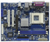
...any modifications of this motherboard, please visit our website for a 3.5-in , 24.4 cm x 19.8 cm) One ASRock K7S41GX2 Quick Installation Guide One ASRock K7S41GX2 Support CD One 80-conductor Ultra ATA 66/100/133 IDE Ribbon Cable One Ribbon Cable for specific information about the model you... and the BIOS software might be updated, the content of this manual, chapter 1 and 2 contain introduction of the Support CD. www.asrock.com/support/index.asp 1.1 Package Contents One ASRock K7S41GX2 Motherboard (Micro ATX Form Factor: 9.6-in x 7.8-in Floppy Drive One I/O Panel Shield 5 Chapter 3 and 4 ...
...any modifications of this motherboard, please visit our website for a 3.5-in , 24.4 cm x 19.8 cm) One ASRock K7S41GX2 Quick Installation Guide One ASRock K7S41GX2 Support CD One 80-conductor Ultra ATA 66/100/133 IDE Ribbon Cable One Ribbon Cable for specific information about the model you... and the BIOS software might be updated, the content of this manual, chapter 1 and 2 contain introduction of the Support CD. www.asrock.com/support/index.asp 1.1 Package Contents One ASRock K7S41GX2 Motherboard (Micro ATX Form Factor: 9.6-in x 7.8-in Floppy Drive One I/O Panel Shield 5 Chapter 3 and 4 ...
User Manual
Page 6
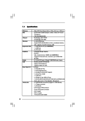
...Platform CPU Chipset Memory Expansion Slot Graphics Audio LAN Rear Panel I /O Panel - 1 x PS/2 Mouse Port - 1 x PS/2 Keyboard Port - 1 x Parallel Port (ECP/EPP Support) - 1 x Serial Port: COM1 - 1 x VGA Port - 4 x Ready-to 2048x1536 @ 75Hz - 5.1 CH AC'97 Audio (C-Media® CMI9739A Audio Codec) - ... Floppy connector - 1 x IR header - Front panel audio header 6 Southbridge: SiS® 963L - 2 x DDR DIMM slots - Support DDR 400/333/266 non-ECC, un-buffered memory - Supports D-Sub with LED (ACT/LINK LED and SPEED LED) - resolution up to -Use USB 2.0 Ports - 1 x RJ-45 LAN Port...
...Platform CPU Chipset Memory Expansion Slot Graphics Audio LAN Rear Panel I /O Panel - 1 x PS/2 Mouse Port - 1 x PS/2 Keyboard Port - 1 x Parallel Port (ECP/EPP Support) - 1 x Serial Port: COM1 - 1 x VGA Port - 4 x Ready-to 2048x1536 @ 75Hz - 5.1 CH AC'97 Audio (C-Media® CMI9739A Audio Codec) - ... Floppy connector - 1 x IR header - Front panel audio header 6 Southbridge: SiS® 963L - 2 x DDR DIMM slots - Support DDR 400/333/266 non-ECC, un-buffered memory - Supports D-Sub with LED (ACT/LINK LED and SPEED LED) - resolution up to -Use USB 2.0 Ports - 1 x RJ-45 LAN Port...

User Manual
Page 7
... damage to the components and devices of your own risk and expense. It should be done at your system. - 1 x USB 2.0 header (supports 2 USB 2.0 ports) (see CAUTION 7) - ACPI 1.1 Compliance Wake Up Events - ASRock U-COP (see CAUTION 3) BIOS Feature - 2Mb AMI Legal BIOS - Microsoft® Windows® 2000 / XP compliant Certifications - FCC, CE, WHQL...
... damage to the components and devices of your own risk and expense. It should be done at your system. - 1 x USB 2.0 header (supports 2 USB 2.0 ports) (see CAUTION 7) - ACPI 1.1 Compliance Wake Up Events - ASRock U-COP (see CAUTION 3) BIOS Feature - 2Mb AMI Legal BIOS - Microsoft® Windows® 2000 / XP compliant Certifications - FCC, CE, WHQL...
User Manual
Page 13
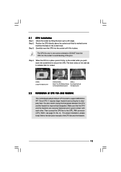
... CPU Fan and Heatsink This motherboard adopts 462-pin CPU socket to a 90o angle. CPU Installation Unlock the socket by lifting the lever up to support AMD Athlon XP / Duron CPU. Lever 90° Up STEP 1: Lift Up The Socket Lever CPU Marked Corner Socket Marked Corner STEP 2/STEP 3: STEP 4: Match...
... CPU Fan and Heatsink This motherboard adopts 462-pin CPU socket to a 90o angle. CPU Installation Unlock the socket by lifting the lever up to support AMD Athlon XP / Duron CPU. Lever 90° Up STEP 1: Lift Up The Socket Lever CPU Marked Corner Socket Marked Corner STEP 2/STEP 3: STEP 4: Match...
User Manual
Page 18
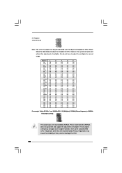
... to all multiplier-locked or even some unlocked AMD CPU. You do not have to adjust the multiplier of CPU. Please understand that ASRock does not guarantee and support the adjustment of multiplier. These jumpers setting may cause the instability of the system or damage the CPU. 18 J1 Jumpers (see p.10...
... to all multiplier-locked or even some unlocked AMD CPU. You do not have to adjust the multiplier of CPU. Please understand that ASRock does not guarantee and support the adjustment of multiplier. These jumpers setting may cause the instability of the system or damage the CPU. 18 J1 Jumpers (see p.10...
User Manual
Page 19
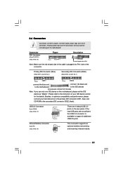
.... Connector FDD Connector (33-pin FLOPPY1) (see p.10 No. 7) PIN1 IDE1 PIN1 IDE2 connect the blue end connect the black end to the motherboard to support 2 additional USB 2.0 ports. Please refer to the secondary IDE connector (IDE2, black). USB 2.0 Connector (9-pin USB45) (see p.10 No. 19) IRTX +5V DUMMY 1 GND IRRX...
.... Connector FDD Connector (33-pin FLOPPY1) (see p.10 No. 7) PIN1 IDE1 PIN1 IDE2 connect the blue end connect the black end to the motherboard to support 2 additional USB 2.0 ports. Please refer to the secondary IDE connector (IDE2, black). USB 2.0 Connector (9-pin USB45) (see p.10 No. 19) IRTX +5V DUMMY 1 GND IRRX...

User Manual
Page 21
Therefore, the drivers you install can be auto-detected and listed on the support CD driver page. Please follow the order from up to bottom side to your optical drive first. Then, the drivers compatible to your system can work properly. 21 2.7 Driver Installation Guide To install the drivers to your system, please insert the support CD to install those required drivers.
Therefore, the drivers you install can be auto-detected and listed on the support CD driver page. Please follow the order from up to bottom side to your optical drive first. Then, the drivers compatible to your system can work properly. 21 2.7 Driver Installation Guide To install the drivers to your system, please insert the support CD to install those required drivers.
User Manual
Page 25
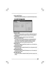
The default value is [2.6V]. 25 If you can support CAS latency=3T. Please note that delivers unparalleled power savings. The default value is [Disabled]. You may select other value as the operating frequency: [133MHz ...
The default value is [2.6V]. 25 If you can support CAS latency=3T. Please note that delivers unparalleled power savings. The default value is [Disabled]. You may select other value as the operating frequency: [133MHz ...
User Manual
Page 28
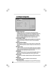
...] and [Disabled]. OnBoard LAN This allows you want to enable this function, please set this option to select the size of AGP fast write protocol support. Intelligent Energy Saver Intelligent Energy Saver is [Disabled]. If you to enable or disable the feature of share memory for an AGP 2.0 card. You may...
...] and [Disabled]. OnBoard LAN This allows you want to enable this function, please set this option to select the size of AGP fast write protocol support. Intelligent Energy Saver Intelligent Energy Saver is [Disabled]. If you to enable or disable the feature of share memory for an AGP 2.0 card. You may...
User Manual
Page 29
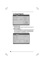
Check Ready Bit Use this feature if the OS supports it. Select [Auto] will enable this item to enable or disable the feature Check Ready Bit. If [Power Off] is selected, the AC/power resumes ...
Check Ready Bit Use this feature if the OS supports it. Select [Auto] will enable this item to enable or disable the feature Check Ready Bit. If [Power Off] is selected, the AC/power resumes ...
User Manual
Page 30
... Advanced Primary IDE Master Device Vendor Size LBA Mode Block Mode PIO Mode Async DMA Ultra DMA S.M.A.R.T. :Hard Disk :MAXTOR 6L080J4 :80.0 GB :Supported :16Sectors :4 :MultiWord DMA-2 :Ultra DMA-6 :Supported Type LBA/Large Mode Block (Multi-Sector Transfer) PIO Mode DMA Mode S.M.A.R.T. 32Bit Data Transfer [Auto] [Auto] [Auto] [Auto] [Auto] [Disabled] [Disabled...
... Advanced Primary IDE Master Device Vendor Size LBA Mode Block Mode PIO Mode Async DMA Ultra DMA S.M.A.R.T. :Hard Disk :MAXTOR 6L080J4 :80.0 GB :Supported :16Sectors :4 :MultiWord DMA-2 :Ultra DMA-6 :Supported Type LBA/Large Mode Block (Multi-Sector Transfer) PIO Mode DMA Mode S.M.A.R.T. 32Bit Data Transfer [Auto] [Auto] [Auto] [Auto] [Auto] [Disabled] [Disabled...

User Manual
Page 35
... [Disabled] to use only under legacy OS and BIOS setup when [Disabled] is selected. Enables legacy support if USB devices are not allowed to enable or disable the USB 2.0 support. USB devices are connected. [Disabled] - If you have USB compatibility issue, it is [Enabled]. ...the use under BIOS setup and Windows / Linux OS. 35 3.4.8 USB Configuration BIOS SETUP UTILITY Advanced USB Configuration USB Controller USB 2.0 Support Legacy USB Support [Enabled] [Enabled] [Enabled] To enable or disable the onboard USB controllers. +F1 F9 F10 ESC Select Screen Select Item Change ...
... [Disabled] to use only under legacy OS and BIOS setup when [Disabled] is selected. Enables legacy support if USB devices are not allowed to enable or disable the USB 2.0 support. USB devices are connected. [Disabled] - If you have USB compatibility issue, it is [Enabled]. ...the use under BIOS setup and Windows / Linux OS. 35 3.4.8 USB Configuration BIOS SETUP UTILITY Advanced USB Configuration USB Controller USB 2.0 Support Legacy USB Support [Enabled] [Enabled] [Enabled] To enable or disable the onboard USB controllers. +F1 F9 F10 ESC Select Screen Select Item Change ...

User Manual
Page 40
...asrock.com; Install the necessary drivers to display the menus. 4.2.2 Drivers Menu The Drivers Menu shows the available devices drivers if the system detects installed devices. If the Main Menu did not appear automatically, locate and double click on a specific item then follow the installation wizard to know more information. 4.2 Support... The Utilities Menu shows the applications software that will enhance the motherboard features. 4.2.1 Running The Support CD To begin using the support CD, insert the CD into your computer. Because motherboard settings and hardware options vary, use ...
...asrock.com; Install the necessary drivers to display the menus. 4.2.2 Drivers Menu The Drivers Menu shows the available devices drivers if the system detects installed devices. If the Main Menu did not appear automatically, locate and double click on a specific item then follow the installation wizard to know more information. 4.2 Support... The Utilities Menu shows the applications software that will enhance the motherboard features. 4.2.1 Running The Support CD To begin using the support CD, insert the CD into your computer. Because motherboard settings and hardware options vary, use ...

Quick Installation Guide
Page 4
... found in the user manual presented in Floppy Drive One I/O Panel Shield 4 ASRock K7S41GX2 Motherboard English www.asrock.com/support/index.asp 1.1 Package Contents One ASRock K7S41GX2 Motherboard (Micro ATX Form Factor: 9.6-in x 7.8-in, 24.4 cm x 19.8 cm) One ASRock K7S41GX2 Quick Installation Guide One ASRock K7S41GX2 Support CD One 80-conductor Ultra ATA 66/100/133 IDE Ribbon Cable One...
... found in the user manual presented in Floppy Drive One I/O Panel Shield 4 ASRock K7S41GX2 Motherboard English www.asrock.com/support/index.asp 1.1 Package Contents One ASRock K7S41GX2 Motherboard (Micro ATX Form Factor: 9.6-in x 7.8-in, 24.4 cm x 19.8 cm) One ASRock K7S41GX2 Quick Installation Guide One ASRock K7S41GX2 Support CD One 80-conductor Ultra ATA 66/100/133 IDE Ribbon Cable One...

Quick Installation Guide
Page 5
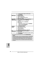
... FAN connector - 20 pin ATX power connector - Micro ATX Form Factor: 9.6-in x 7.8-in header - Southbridge: SiS® 963L - 2 x DDR DIMM slots - Supports Wake-On-LAN I /O Connector - Front panel audio header English 5 ASRock K7S41GX2 Motherboard Realtek LAN PHY RTL8201EL - CD in , 24.4 cm x 19.8 cm - shared memory 128MB (see CAUTION 1) - 1 x AMR slot - 2 x PCI slots...
... FAN connector - 20 pin ATX power connector - Micro ATX Form Factor: 9.6-in x 7.8-in header - Southbridge: SiS® 963L - 2 x DDR DIMM slots - Supports Wake-On-LAN I /O Connector - Front panel audio header English 5 ASRock K7S41GX2 Motherboard Realtek LAN PHY RTL8201EL - CD in , 24.4 cm x 19.8 cm - shared memory 128MB (see CAUTION 1) - 1 x AMR slot - 2 x PCI slots...
Quick Installation Guide
Page 6
... (see CAUTION 8) * For detailed product information, please visit our website: http://www.asrock.com WARNING Please realize that there is a certain risk involved with overclocking, including adjusting the...+5V, +3.3V, Vcore OS - We are not responsible for possible damage caused by overclocking. SMBIOS 2.3.1 Support Support CD - Instant Boot - Chassis Temperature Sensing - English 6 ASRock K7S41GX2 Motherboard - 1 x USB 2.0 header (supports 2 USB 2.0 ports) (see CAUTION 4) - Supports "Plug and Play" - Intelligent Energy Saver (see CAUTION 3) BIOS Feature - 2Mb AMI Legal BIOS -...
... (see CAUTION 8) * For detailed product information, please visit our website: http://www.asrock.com WARNING Please realize that there is a certain risk involved with overclocking, including adjusting the...+5V, +3.3V, Vcore OS - We are not responsible for possible damage caused by overclocking. SMBIOS 2.3.1 Support Support CD - Instant Boot - Chassis Temperature Sensing - English 6 ASRock K7S41GX2 Motherboard - 1 x USB 2.0 header (supports 2 USB 2.0 ports) (see CAUTION 4) - Supports "Plug and Play" - Intelligent Energy Saver (see CAUTION 3) BIOS Feature - 2Mb AMI Legal BIOS -...

Quick Installation Guide
Page 10
...This motherboard adopts 462-pin CPU socket to secure the CPU. The lever clicks on the socket while you push down the socket lever to support AMD Athlon XP / Duron CPU. 2.1 CPU Installation Step 1. It requires larger heatsink and cooling fan to avoid bending of the socket lever.... the CPU and the heatsink to improve heat dissipation. Make sure that its marked corner matches the base of the pins. English 10 ASRock K7S41GX2 Motherboard Step 4. Position the CPU directly above the socket such that the CPU and the heatsink are securely fastened and in one correct orientation...
...This motherboard adopts 462-pin CPU socket to secure the CPU. The lever clicks on the socket while you push down the socket lever to support AMD Athlon XP / Duron CPU. 2.1 CPU Installation Step 1. It requires larger heatsink and cooling fan to avoid bending of the socket lever.... the CPU and the heatsink to improve heat dissipation. Make sure that its marked corner matches the base of the pins. English 10 ASRock K7S41GX2 Motherboard Step 4. Position the CPU directly above the socket such that the CPU and the heatsink are securely fastened and in one correct orientation...
Quick Installation Guide
Page 15
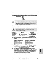
... jumper caps over the connectors will cause permanent damage of the connector. English 15 ASRock K7S41GX2 Motherboard Please understand that ASRock does not guarantee and support the adjustment of the system or damage the CPU. 2.6 Connectors Connectors are not provided by ASRock. Besides, to optimize compatibility and performance, please connect your IDE device vendor for...
... jumper caps over the connectors will cause permanent damage of the connector. English 15 ASRock K7S41GX2 Motherboard Please understand that ASRock does not guarantee and support the adjustment of the system or damage the CPU. 2.6 Connectors Connectors are not provided by ASRock. Besides, to optimize compatibility and performance, please connect your IDE device vendor for...
Quick Installation Guide
Page 16
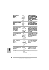
...(9-pin PANEL1) (see p.2 No. 12) Please connect the chassis speaker to this connector. This is available to the ground pin. 16 ASRock K7S41GX2 Motherboard This connector accommodates several system front panel functions. English Chassis Speaker Connector (4-pin SPEAKER 1) (see p.2 No. 14) Chassis Fan Connector ...(3-pin CHA_FAN1) (see p.2 No. 13) There are not sufficient, this connector and match the black wire to support 2 additional USB 2.0 ports. AUX1 CD1 These connectors allow you to this USB 2.0 connector is an interface for front panel audio cable ...
...(9-pin PANEL1) (see p.2 No. 12) Please connect the chassis speaker to this connector. This is available to the ground pin. 16 ASRock K7S41GX2 Motherboard This connector accommodates several system front panel functions. English Chassis Speaker Connector (4-pin SPEAKER 1) (see p.2 No. 14) Chassis Fan Connector ...(3-pin CHA_FAN1) (see p.2 No. 13) There are not sufficient, this connector and match the black wire to support 2 additional USB 2.0 ports. AUX1 CD1 These connectors allow you to this USB 2.0 connector is an interface for front panel audio cable ...


