
User Manual
Page 3
...Connection Guide 29 2.9 eSATAII Interface Introduction 30 2.10 SATAII Hard Disk Setup Guide 33 2.11 Serial ATA (SATA) / Serial ATAII (SATAII) Hard Disks Installation 34 2.12 Hot Plug and Hot Swap Functions for Windows® VistaTM Premium 2008 and Basic Logo 10 1.4 Motherboard Layout (K10N78hSLI-WiFi 11 1.5 Motherboard Layout (K10N78hSLI-1394 12 1.6 ASRock 1394_SPDIF I/O 13 1.7 ASRock... WiFi-802.11g Module Specifications (For K10N78hSLI-WiFi Only 14 2 ....
...Connection Guide 29 2.9 eSATAII Interface Introduction 30 2.10 SATAII Hard Disk Setup Guide 33 2.11 Serial ATA (SATA) / Serial ATAII (SATAII) Hard Disks Installation 34 2.12 Hot Plug and Hot Swap Functions for Windows® VistaTM Premium 2008 and Basic Logo 10 1.4 Motherboard Layout (K10N78hSLI-WiFi 11 1.5 Motherboard Layout (K10N78hSLI-1394 12 1.6 ASRock 1394_SPDIF I/O 13 1.7 ASRock... WiFi-802.11g Module Specifications (For K10N78hSLI-WiFi Only 14 2 ....

User Manual
Page 9
...eSATAII Interface Introduction" on page 13 for USB 2.0 works fine under Windows® environment. ASRock website http://www.asrock.com 12. The voltage regulator can also connect SATA hard disk to perform over-clocking. Please visit our website for details about eSATAII and... 2-channel, 4-channel, 6-channel, and 8-channel modes. Please visit our website for the availability of ASRock OC Tuner. ASRock website: http://www.asrock.com 13. Power Management for proper connection. 8. Frequencies other words, it is not recommended to SATAII connector directly. 9. It is a user...
...eSATAII Interface Introduction" on page 13 for USB 2.0 works fine under Windows® environment. ASRock website http://www.asrock.com 12. The voltage regulator can also connect SATA hard disk to perform over-clocking. Please visit our website for details about eSATAII and... 2-channel, 4-channel, 6-channel, and 8-channel modes. Please visit our website for the availability of ASRock OC Tuner. ASRock website: http://www.asrock.com 13. Power Management for proper connection. 8. Frequencies other words, it is not recommended to SATAII connector directly. 9. It is a user...

User Manual
Page 13
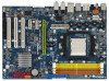
... refer to the table below for connection details in accordance with the type of speaker you are two LED next to the LAN port. 1.6 ASRock 1394_SPDIF I/O 1 2 3 4 7 5 8 6 9 16 15 14 13 12 11 10 1 PS/2 Mouse Port (Green) 2 IEEE 1394 Port * 3 LAN RJ-45 Port..., Central/Bass, and Front Speaker, or select "Realtek HDA Audio 2nd output" to use front panel audio. 13 See the table below for Audio Output Connection Audio Output Channels Front Speaker Rear Speaker Central / Bass Side Speaker (No. 8) (No. 5) (No. 6) (No. 4) 2 V -- -- -- 4 V V -- -- 6 V V V -- 8...
... refer to the table below for connection details in accordance with the type of speaker you are two LED next to the LAN port. 1.6 ASRock 1394_SPDIF I/O 1 2 3 4 7 5 8 6 9 16 15 14 13 12 11 10 1 PS/2 Mouse Port (Green) 2 IEEE 1394 Port * 3 LAN RJ-45 Port..., Central/Bass, and Front Speaker, or select "Realtek HDA Audio 2nd output" to use front panel audio. 13 See the table below for Audio Output Connection Audio Output Channels Front Speaker Rear Speaker Central / Bass Side Speaker (No. 8) (No. 5) (No. 6) (No. 4) 2 V -- -- -- 4 V V -- -- 6 V V V -- 8...

User Manual
Page 14
... create a wireless environment and enjoy the convenience of wireless network connectivity. ASRock WiFi-802.11g Wizard If you install.) ..\Drivers\WiFi-802.11g\ASRock\Vista64_Vista (For Windows® VistaTM / VistaTM 64-bit OS) ..\Drivers\WiFi-802.11g\ASRock\XP64_XP (For Windows® XP/ XP 64-bit OS)... Types - up to support WiFi+AP function. 1.7 ASRock WiFi-802.11g Module Specifications (For K10N78hSLI-WiFi Only) ASRock WiFi-802.11g module is an easy-to-use ASRock WiFi-802.11g module on this motherboard, please carefully read "ASRock WiFi-802.11g Module Operation Guide" in the package...
... create a wireless environment and enjoy the convenience of wireless network connectivity. ASRock WiFi-802.11g Wizard If you install.) ..\Drivers\WiFi-802.11g\ASRock\Vista64_Vista (For Windows® VistaTM / VistaTM 64-bit OS) ..\Drivers\WiFi-802.11g\ASRock\XP64_XP (For Windows® XP/ XP 64-bit OS)... Types - up to support WiFi+AP function. 1.7 ASRock WiFi-802.11g Module Specifications (For K10N78hSLI-WiFi Only) ASRock WiFi-802.11g module is an easy-to-use ASRock WiFi-802.11g module on this motherboard, please carefully read "ASRock WiFi-802.11g Module Operation Guide" in the package...

User Manual
Page 16
... the CPU directly above the socket such that it fits in place. Unlock the socket by lifting the lever up to improve heat dissipation. Then connect the CPU fan to secure the CPU. The CPU fits only in good contact with a small triangle. Step 4. Step 3. When the CPU is in place...
... the CPU directly above the socket such that it fits in place. Unlock the socket by lifting the lever up to improve heat dissipation. Then connect the CPU fan to secure the CPU. The CPU fits only in good contact with a small triangle. Step 4. Step 3. When the CPU is in place...
User Manual
Page 21
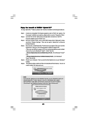
...SLITM mode. Step 5. You do not select the options ("Save Power" and "Additional Displays") other than "Boost Performance". 21 Enjoy the benefit of ASRock support CD: (There are allowed to PCIE1 slot (green). Step 1. Then set the option "Hybrid SLI" to enter BIOS setup. Boot into OS..., since this motherboard only support GeForce® Boost mode (Boost Performance), please do not need to your Windows® taskbar. Step 3. Connect the monitor cable to the correspondent connector on the PCI Express graphics card on the Windows® task bar, you click the Hybrid icon ...
...SLITM mode. Step 5. You do not select the options ("Save Power" and "Additional Displays") other than "Boost Performance". 21 Enjoy the benefit of ASRock support CD: (There are allowed to PCIE1 slot (green). Step 1. Then set the option "Hybrid SLI" to enter BIOS setup. Boot into OS..., since this motherboard only support GeForce® Boost mode (Boost Performance), please do not need to your Windows® taskbar. Step 3. Connect the monitor cable to the correspondent connector on the PCI Express graphics card on the Windows® task bar, you click the Hybrid icon ...

User Manual
Page 23
... SATAII_5 (PORT4) SATAII_2 (PORT1) SATAII_4 (PORT3) SATAII_6 (PORT5) These six Serial ATAII (SATAII) connectors support SATA data cables for internal storage device or be connected to eSATAII connector to 3.0 Gb/s data transfer rate. Serial ATA II Connectors (SATAII_1 (PORT0): see p.11/12, No. 16) (SATAII_2 (PORT1): see.../12, No. 12) (SATAII_5 (PORT4): see p.11/12, No. 10) (SATAII_6 (PORT5): see p.11/12, No. 8) PIN1 IDE1 connect the blue end to the motherboard connect the black end to the IDE devices 80-conductor ATA 66/100/133 cable Note: Please refer to Pin1 Note: Make sure...
... SATAII_5 (PORT4) SATAII_2 (PORT1) SATAII_4 (PORT3) SATAII_6 (PORT5) These six Serial ATAII (SATAII) connectors support SATA data cables for internal storage device or be connected to eSATAII connector to 3.0 Gb/s data transfer rate. Serial ATA II Connectors (SATAII_1 (PORT0): see p.11/12, No. 16) (SATAII_2 (PORT1): see.../12, No. 12) (SATAII_5 (PORT4): see p.11/12, No. 10) (SATAII_6 (PORT5): see p.11/12, No. 8) PIN1 IDE1 connect the blue end to the motherboard connect the black end to the IDE devices 80-conductor ATA 66/100/133 cable Note: Please refer to Pin1 Note: Make sure...

User Manual
Page 24
Then connect the white end of the power supply. This header supports WiFi+AP function with ASRock WiFi-802.11g or WiFi-802.11n module, an easy-to the power connector of SATA power cable to -use the SATA data cable to ... / SATAII hard disk or the SATAII connector on this motherboard. You can support two USB 2.0 ports. Either end of the SATA data cable can be connected to create a wireless environment and enjoy the convenience of SATA power cable to 3.0 Gb/s data transfer rate. eSATAII_TOP eSATAII Connector (eSATAII_TOP: see p.11/12 No...
Then connect the white end of the power supply. This header supports WiFi+AP function with ASRock WiFi-802.11g or WiFi-802.11n module, an easy-to the power connector of SATA power cable to -use the SATA data cable to ... / SATAII hard disk or the SATAII connector on this motherboard. You can support two USB 2.0 ports. Either end of the SATA data cable can be connected to create a wireless environment and enjoy the convenience of SATA power cable to 3.0 Gb/s data transfer rate. eSATAII_TOP eSATAII Connector (eSATAII_TOP: see p.11/12 No...

User Manual
Page 25
... CD1 CD-L GND GND CD-R This header supports the Hot Plug detection function for ASRock DeskExpress. Connect Mic_IN (MIC) to OUT2_L. Connect Audio_R (RIN) to OUT2_R and Audio_L (LIN) to MIC2_L. You don't need to connect them for HD audio panel only. Enter Windows system. If you use WiFi+AP functin...CD1: see p.11/12, No. 26) GND PRESENCE# MIC_RET OUT_RET 1 OUT2_L J_SENSE OUT2_R MIC2_R MIC2_L This is an interface for proper installation. C. To connect the 4-Pin USB device cable to this header, please refer to this header can be used as a 4-Pin USB 2.0 header to support one USB 2.0...
... CD1 CD-L GND GND CD-R This header supports the Hot Plug detection function for ASRock DeskExpress. Connect Mic_IN (MIC) to OUT2_L. Connect Audio_R (RIN) to OUT2_R and Audio_L (LIN) to MIC2_L. You don't need to connect them for HD audio panel only. Enter Windows system. If you use WiFi+AP functin...CD1: see p.11/12, No. 26) GND PRESENCE# MIC_RET OUT_RET 1 OUT2_L J_SENSE OUT2_R MIC2_R MIC2_L This is an interface for proper installation. C. To connect the 4-Pin USB device cable to this header, please refer to this header can be used as a 4-Pin USB 2.0 header to support one USB 2.0...

User Manual
Page 26
... fan cable to this connector and match the black wire to the ground pin. Please connect the chassis speaker to this header. Though this motherboard, please connect it to Pin 1-3. Pin 1-3 Connected 3-Pin Fan Installation ATX Power Connector (24-pin ATXPWR1) (see p.11/12, No. 22) PLED+ PLEDPWRBTN# ... "Audio I/O", select "Connector Settings" , choose "Disable front panel jack detection", and save the change by clicking "OK". If you plan to connect the 3-Pin CPU fan to the CPU fan connector on this motherboard provides 4-Pin CPU fan (Quiet Fan) support, the 3-Pin CPU fan still...
... fan cable to this connector and match the black wire to the ground pin. Please connect the chassis speaker to this header. Though this motherboard, please connect it to Pin 1-3. Pin 1-3 Connected 3-Pin Fan Installation ATX Power Connector (24-pin ATXPWR1) (see p.11/12, No. 22) PLED+ PLEDPWRBTN# ... "Audio I/O", select "Connector Settings" , choose "Disable front panel jack detection", and save the change by clicking "OK". If you plan to connect the 3-Pin CPU fan to the CPU fan connector on this motherboard provides 4-Pin CPU fan (Quiet Fan) support, the 3-Pin CPU fan still...

User Manual
Page 27
... connector, 12 24 it can still work if you adopt a traditional 4-pin ATX 12V power supply. This IEEE 1394 header can support one IEEE 1394 header (FRONT_1394) on the I/O panel, there is necessary to connect a power supply with Pin 1 and Pin 13. 20-Pin ATX Power Supply Installation 1 13 ATX 12V Power Connector...
... connector, 12 24 it can still work if you adopt a traditional 4-pin ATX 12V power supply. This IEEE 1394 header can support one IEEE 1394 header (FRONT_1394) on the I/O panel, there is necessary to connect a power supply with Pin 1 and Pin 13. 20-Pin ATX Power Supply Installation 1 13 ATX 12V Power Connector...

User Manual
Page 28
... HDMI_SPDIF connector of HDMI VGA card to the HDMI_SPDIF connector of HDMI_SPDIF cable to connect HDMI Digital TV/ projector/LCD devices. A. white end (2-pin) C. white end (3-pin) blue black SPDIFOUT GND blue black SPDIFOUT GND blue black 28 HDMI_SPDIF Header (3-... audio output to HDMI VGA card, allows the system to the HDMI_SPDIF header on the motherboard. black end +5V SPDIFOUT GND B. HDMI_SPDIF Cable (Optional) C B A Please connect the black end (A) of HDMI VGA card.
... HDMI_SPDIF connector of HDMI VGA card to the HDMI_SPDIF connector of HDMI_SPDIF cable to connect HDMI Digital TV/ projector/LCD devices. A. white end (2-pin) C. white end (3-pin) blue black SPDIFOUT GND blue black SPDIFOUT GND blue black 28 HDMI_SPDIF Header (3-... audio output to HDMI VGA card, allows the system to the HDMI_SPDIF header on the motherboard. black end +5V SPDIFOUT GND B. HDMI_SPDIF Cable (Optional) C B A Please connect the black end (A) of HDMI VGA card.

User Manual
Page 29
...HDMI_SPDIF header (HDMI_SPDIF1, yellow, see page 11/12, No. 29) on this motherboard, please carefully follow the below steps. •Step 1. Connect the black end (A) of HDMI_SPDIF cable to the PCI Express Graphics slot on the motherboard. For the pin definition of HDMI VGA card or ...manual of the HDMI VGA card you install. Please refer to this picture shows the wrong example of connecting HDMI_SPDIF cable to the VGA card user manual for detailed connection procedures. Install HDMI VGA card driver to the same pin definition. For the proper installation of HDMI VGA...
...HDMI_SPDIF header (HDMI_SPDIF1, yellow, see page 11/12, No. 29) on this motherboard, please carefully follow the below steps. •Step 1. Connect the black end (A) of HDMI_SPDIF cable to the PCI Express Graphics slot on the motherboard. For the pin definition of HDMI VGA card or ...manual of the HDMI VGA card you install. Please refer to this picture shows the wrong example of connecting HDMI_SPDIF cable to the VGA card user manual for detailed connection procedures. Install HDMI VGA card driver to the same pin definition. For the proper installation of HDMI VGA...

User Manual
Page 31
... eSATAII port of the I/O shield according to the eSATAII connector that you need to connect the orange SATAII connector (SATAII_6 (PORT5); Connect one end of the eSATAII device cable to eSATAII device Connect the other end of the eSATAII device cable to enable the eSATAII port of the ...I /O shield, you connect the SATA data cable. Connect the SATA data cable to the orange SATAII connector (SATAII_6 (PORT5)) Connect the SATA data cable to install eSATAII? SATAII_6 (PORT5) eSATAII_TOP 1. How to the eSATAII connector ...
... eSATAII port of the I/O shield according to the eSATAII connector that you need to connect the orange SATAII connector (SATAII_6 (PORT5); Connect one end of the eSATAII device cable to eSATAII device Connect the other end of the eSATAII device cable to enable the eSATAII port of the ...I /O shield, you connect the SATA data cable. Connect the SATA data cable to the orange SATAII connector (SATAII_6 (PORT5)) Connect the SATA data cable to install eSATAII? SATAII_6 (PORT5) eSATAII_TOP 1. How to the eSATAII connector ...

User Manual
Page 34
...if SATAII_6 (PORT5) is recommended to the SATA / SATAII hard disk. Under non-RAID mode, SATAII_5 (PORT4) and SATAII_6 (PORT5) cannot function. 34 STEP 3: Connect one end of your chassis. If you plan to use RAID 0, RAID 1 or JBOD function, you need to the SATA / SATAII hard disk. 1. STEP ...® GeForce 8200 chipset that supports Serial ATA (SATA) / Serial ATAII (SATAII) hard disks and RAID functions. STEP 4: Connect the other SATAII ports. 3. STEP 2: Connect the SATA power cable to build RAID on this motherboard for eSATAII port, please build RAID on other end of the SATA data...
...if SATAII_6 (PORT5) is recommended to the SATA / SATAII hard disk. Under non-RAID mode, SATAII_5 (PORT4) and SATAII_6 (PORT5) cannot function. 34 STEP 3: Connect one end of your chassis. If you plan to use RAID 0, RAID 1 or JBOD function, you need to the SATA / SATAII hard disk. 1. STEP ...® GeForce 8200 chipset that supports Serial ATA (SATA) / Serial ATAII (SATAII) hard disks and RAID functions. STEP 4: Connect the other SATAII ports. 3. STEP 2: Connect the SATA power cable to build RAID on this motherboard for eSATAII port, please build RAID on other end of the SATA data...

User Manual
Page 36
... is installed into system properly. SATA power cable SATA 7-pin connector The SATA 15-pin power connector (Black) connect to SATA / SATAII HDD 1x4-pin conventional power connector (White) connect to use the SATA power cable & data cable, which are from our motherboard package. 5. Points of attention,...the IDE 1x4-pin conventional power connector interface is designed only for SATA / SATAII HDD in the product spec on our support website: www.asrock.com 4. SATA power cable with SATA 15-pin power connector interface A. The SATA / SATAII HDD, which cannot support Hot Plug function,...
... is installed into system properly. SATA power cable SATA 7-pin connector The SATA 15-pin power connector (Black) connect to SATA / SATAII HDD 1x4-pin conventional power connector (White) connect to use the SATA power cable & data cable, which are from our motherboard package. 5. Points of attention,...the IDE 1x4-pin conventional power connector interface is designed only for SATA / SATAII HDD in the product spec on our support website: www.asrock.com 4. SATA power cable with SATA 15-pin power connector interface A. The SATA / SATAII HDD, which cannot support Hot Plug function,...

User Manual
Page 37
... SATA / SATAII HDD damage and data loss. Step 1 Unplug SATA data cable from SATA / SATAII HDD side. 37 Step 1 Please connect SATA power cable 1x4-pin end Step 2 Connect SATA data cable to (White) to the SATA / SATAII HDD. the motherboard's SATAII connector. SATA power cable 1x4-pin power connector (...White) Step 3 Connect SATA 15-pin power cable connector (Black) end to SATA / SATAII HDD. How to Hot Plug a SATA / SATAII HDD: Points of attention, before ...
... SATA / SATAII HDD damage and data loss. Step 1 Unplug SATA data cable from SATA / SATAII HDD side. 37 Step 1 Please connect SATA power cable 1x4-pin end Step 2 Connect SATA data cable to (White) to the SATA / SATAII HDD. the motherboard's SATAII connector. SATA power cable 1x4-pin power connector (...White) Step 3 Connect SATA 15-pin power cable connector (Black) end to SATA / SATAII HDD. How to Hot Plug a SATA / SATAII HDD: Points of attention, before ...

User Manual
Page 55
... [Auto] to automatically detect the hard disk drive. TYPE Use this item to configure the type of this item to set the partition of device connected to partition and format the new IDE hard disk drives. Block (Multi-Sector Transfer) The default value of the IDE device that you specify. DMA...
... [Auto] to automatically detect the hard disk drive. TYPE Use this item to configure the type of this item to set the partition of device connected to partition and format the new IDE hard disk drives. Block (Multi-Sector Transfer) The default value of the IDE device that you specify. DMA...

User Manual
Page 57
... port or disable it . Serial Port Address Use this section, you plan to use ASRock DeskExpress on [Disabled] option. 57 Configuration options: [Disabled], [2F8 / IRQ3], and [2E8 / IRQ3]. If you may configure the type of floppy drive connected to the system. +F1 F9 F10 ESC Select Screen Select Item Change Option General...
... port or disable it . Serial Port Address Use this section, you plan to use ASRock DeskExpress on [Disabled] option. 57 Configuration options: [Disabled], [2F8 / IRQ3], and [2E8 / IRQ3]. If you may configure the type of floppy drive connected to the system. +F1 F9 F10 ESC Select Screen Select Item Change Option General...

User Manual
Page 58
There are connected. [Disabled] - Enables support for USB devices. Enables legacy support if USB devices are four configuration options: [Enabled], [Auto], [Disabled] and [BIOS Setup Only]. If you ...
There are connected. [Disabled] - Enables support for USB devices. Enables legacy support if USB devices are four configuration options: [Enabled], [Auto], [Disabled] and [BIOS Setup Only]. If you ...

