User Manual
Page 2
... without notice, and should not be constructed as a commitment by ASRock. With respect to the contents of this device must accept any interference received, including interference that may appear in this motherboard contains Perchlorate, a toxic substance controlled in any form or by the... names appearing in this manual may be reproduced, transcribed, transmitted, or translated in any defect or error in advance. ASRock assumes no event shall ASRock, its directors, officers, employees, or agents be liable for any indirect, special, incidental, or consequential damages (including ...
... without notice, and should not be constructed as a commitment by ASRock. With respect to the contents of this device must accept any interference received, including interference that may appear in this motherboard contains Perchlorate, a toxic substance controlled in any form or by the... names appearing in this manual may be reproduced, transcribed, transmitted, or translated in any defect or error in advance. ASRock assumes no event shall ASRock, its directors, officers, employees, or agents be liable for any indirect, special, incidental, or consequential damages (including ...
User Manual
Page 3
... 2.12 Serial ATA (SATA) / Serial ATAII (SATAII) Hard Disks Installation 41 2.13 Hot Plug and Hot Swap Functions for 3-Way SLITM Mode .. 11 1.6 Motherboard Layout 12 1.7 ASRock WiFi_SPDIF I/O 13 1.8 ASRock WiFi-802.11g Module Specifications 14 2 . Contents 1 . Introduction 5 1.1 Package Contents 5 1.2 Specifications 6 1.3 Minimum Hardware Requirement Table for Windows® VistaTM Premium 2008 and Basic Logo...
... 2.12 Serial ATA (SATA) / Serial ATAII (SATAII) Hard Disks Installation 41 2.13 Hot Plug and Hot Swap Functions for 3-Way SLITM Mode .. 11 1.6 Motherboard Layout 12 1.7 ASRock WiFi_SPDIF I/O 13 1.8 ASRock WiFi-802.11g Module Specifications 14 2 . Contents 1 . Introduction 5 1.1 Package Contents 5 1.2 Specifications 6 1.3 Minimum Hardware Requirement Table for Windows® VistaTM Premium 2008 and Basic Logo...
User Manual
Page 5
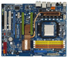
... ASRock K10N780SLIX3-WiFi Motherboard (ATX Form Factor: 12.0-in x 9.6-in, 30.5 cm x 24.4 cm) ASRock K10N780SLIX3-WiFi Quick Installation Guide ASRock K10N780SLIX3-WiFi Support CD ASRock WiFi-802.11g Module Operation Guide Motherboard Accessories One ASRock SLI Bridge One ASRock 3-Way SLI Bridge One ASRock SLI/XFire Switch Card One 80-conductor Ultra ATA 66/100/133 IDE Ribbon Cable One Ribbon Cable for purchasing ASRock K10N780SLIX3-WiFi motherboard, a reliable motherboard...
... ASRock K10N780SLIX3-WiFi Motherboard (ATX Form Factor: 12.0-in x 9.6-in, 30.5 cm x 24.4 cm) ASRock K10N780SLIX3-WiFi Quick Installation Guide ASRock K10N780SLIX3-WiFi Support CD ASRock WiFi-802.11g Module Operation Guide Motherboard Accessories One ASRock SLI Bridge One ASRock 3-Way SLI Bridge One ASRock SLI/XFire Switch Card One 80-conductor Ultra ATA 66/100/133 IDE Ribbon Cable One Ribbon Cable for purchasing ASRock K10N780SLIX3-WiFi motherboard, a reliable motherboard...
User Manual
Page 8
...: +12V, +5V, +3.3V, CPU Vcore OS - Overclocking may be HT1.0 (2000 MT/s). We are not responsible for more information. This motherboard supports Untied Overclocking Technology. Before you install AM2 CPU on page 17 for system usage under Windows® XP and Windows® VistaTM. Due to... http://www.asrock.com 2. For Windows® XP 64-bit and Windows® VistaTM 64-bit with 64-bit CPU, there is a certain risk involved with overclocking, including adjusting the setting in advance. This motherboard supports NVIDIA® SLITM and 3-Way SLITM technology. If you adopt. Hardware...
...: +12V, +5V, +3.3V, CPU Vcore OS - Overclocking may be HT1.0 (2000 MT/s). We are not responsible for more information. This motherboard supports Untied Overclocking Technology. Before you install AM2 CPU on page 17 for system usage under Windows® XP and Windows® VistaTM. Due to... http://www.asrock.com 2. For Windows® XP 64-bit and Windows® VistaTM 64-bit with 64-bit CPU, there is a certain risk involved with overclocking, including adjusting the setting in advance. This motherboard supports NVIDIA® SLITM and 3-Way SLITM technology. If you adopt. Hardware...
User Manual
Page 9
... 'n' Quiet option in the BIOS setup in the future. For audio output, this motherboard supports both stereo and mono modes. WiFi/E header supports WiFi+AP function with ASRock WiFi-802.11g or WiFi-802.11n module, an easy-to improve efficiency when the CPU cores are idle.... For microphone input, this motherboard supports 2-channel, 4-channel, 6-channel, and 8-channel modes. Please read the "...
... 'n' Quiet option in the BIOS setup in the future. For audio output, this motherboard supports both stereo and mono modes. WiFi/E header supports WiFi+AP function with ASRock WiFi-802.11g or WiFi-802.11n module, an easy-to improve efficiency when the CPU cores are idle.... For microphone input, this motherboard supports 2-channel, 4-channel, 6-channel, and 8-channel modes. Please read the "...
User Manual
Page 10
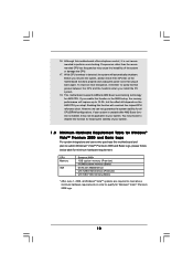
... for Windows® VistaTM Premium 2008 and Basic Logo For system integrators and users who purchase this function for AM2 CPU. Enabling this motherboard offers stepless control, it back again. You may not be applicative to qualify for all Windows® VistaTM systems are required to meet... plan to submit Windows® VistaTM Premium 2008 and Basic logo, please follow below table for minimum hardware requirement. This motherboard supports ASRock AM2 Boost overclocking technology for keeping the stability of the system or damage the CPU. 17. While CPU overheat is not ...
... for Windows® VistaTM Premium 2008 and Basic Logo For system integrators and users who purchase this function for AM2 CPU. Enabling this motherboard offers stepless control, it back again. You may not be applicative to qualify for all Windows® VistaTM systems are required to meet... plan to submit Windows® VistaTM Premium 2008 and Basic logo, please follow below table for minimum hardware requirement. This motherboard supports ASRock AM2 Boost overclocking technology for keeping the stability of the system or damage the CPU. 17. While CPU overheat is not ...
User Manual
Page 14
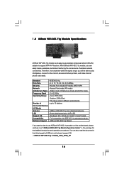
... connect to the internet, access and share printers, and make Internet phone calls easily. With ASRock WiFi-802.11g module, you can also read "ASRock WiFi-802.11g Module Operation Guide" in the package for the detailed introduction and operation procedures. You...data transmission (AIR) LED Support OS - 1.8 ASRock WiFi-802.11g Module Specifications ASRock WiFi-802.11g module is an easy-to-use ASRock WiFi-802.11g module on this motherboard, please carefully read the document in the following path of ASRock motherboard support CD: ..\ ASRock WiFi-802.11g \ Vista64_Vista_XP64_XP 14
... connect to the internet, access and share printers, and make Internet phone calls easily. With ASRock WiFi-802.11g module, you can also read "ASRock WiFi-802.11g Module Operation Guide" in the package for the detailed introduction and operation procedures. You...data transmission (AIR) LED Support OS - 1.8 ASRock WiFi-802.11g Module Specifications ASRock WiFi-802.11g module is an easy-to-use ASRock WiFi-802.11g module on this motherboard, please carefully read the document in the following path of ASRock motherboard support CD: ..\ ASRock WiFi-802.11g \ Vista64_Vista_XP64_XP 14
User Manual
Page 15
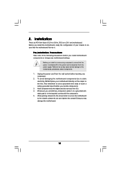
... chassis, please do not over-tighten the screws! Pre-installation Precautions Take note of your motherboard directly on a grounded antistatic pad or in , 30.5 cm x 24.4 cm) motherboard. Before you install motherboard components or change any component, ensure that the power is switched off or the power cord... is an ATX form factor (12.0-in x 9.6-in the bag that the motherboard fits into it on the carpet or the like. To avoid damaging the motherboard components due to use a grounded wrist strap or touch a safety grounded object before touching any component,...
... chassis, please do not over-tighten the screws! Pre-installation Precautions Take note of your motherboard directly on a grounded antistatic pad or in , 30.5 cm x 24.4 cm) motherboard. Before you install motherboard components or change any component, ensure that the power is switched off or the power cord... is an ATX form factor (12.0-in x 9.6-in the bag that the motherboard fits into it on the carpet or the like. To avoid damaging the motherboard components due to use a grounded wrist strap or touch a safety grounded object before touching any component,...
User Manual
Page 16
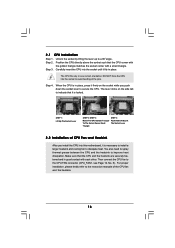
... avoid bending of the pins. Make sure that it is in place, press it firmly on the socket while you install the CPU into this motherboard, it fits in one correct orientation. Step 3. Carefully insert the CPU into the socket to indicate that the CPU and the heatsink are securely fastened...
... avoid bending of the pins. Make sure that it is in place, press it firmly on the socket while you install the CPU into this motherboard, it fits in one correct orientation. Step 3. Carefully insert the CPU into the socket to indicate that the CPU and the heatsink are securely fastened...
User Manual
Page 17
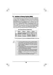
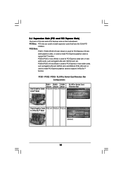
...Populated Populated (3)* Populated Populated Populated Populated * For the configuration (3), please install identical DDR2 DIMMs in all four slots. otherwise, this motherboard, it is not allowed to install them either in the set of yellow slots (DDRII_1 and DDRII_2), or in the set of ...Installation of memory modules in DDRII_1 and DDRII_3, it is recommended to install a DDR memory module into DDR2 slot; Yellow slots; This motherboard also allows you have to the Dual Channel Memory Configuration Table below. In other words, you to activate the Dual Channel Memory Technology...
...Populated Populated (3)* Populated Populated Populated Populated * For the configuration (3), please install identical DDR2 DIMMs in all four slots. otherwise, this motherboard, it is not allowed to install them either in the set of yellow slots (DDRII_1 and DDRII_2), or in the set of ...Installation of memory modules in DDRII_1 and DDRII_3, it is recommended to install a DDR memory module into DDR2 slot; Yellow slots; This motherboard also allows you have to the Dual Channel Memory Configuration Table below. In other words, you to activate the Dual Channel Memory Technology...
User Manual
Page 18
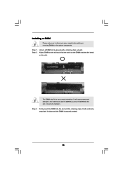
... ends fully snap back in one correct orientation. Step 3. Unlock a DIMM slot by pressing the retaining clips outward. Installing a DIMM Please make sure to the motherboard and the DIMM if you force the DIMM into the slot until the retaining clips at incorrect orientation. notch break notch break The DIMM only...
... ends fully snap back in one correct orientation. Step 3. Unlock a DIMM slot by pressing the retaining clips outward. Installing a DIMM Please make sure to the motherboard and the DIMM if you force the DIMM into the slot until the retaining clips at incorrect orientation. notch break notch break The DIMM only...
User Manual
Page 19
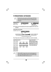
... LAN card, SATA2 card, etc. Blue) is used for PCI Express cards with x1 lane width cards, such as Gigabit LAN card, SATA2 card, and ASRock PCIE_DE card, or used to install PCI Express graphics cards to support 3-Way SLITM function. 2.4 Expansion Slots (PCI and PCI Express Slots) There are used... to install expansion cards that have the 32-bit PCI interface. PCI Slots: PCI slots are 2 PCI slots and 4 PCI Express slots on this motherboard. PCIE4 (PCIE x16 slot;
... LAN card, SATA2 card, etc. Blue) is used for PCI Express cards with x1 lane width cards, such as Gigabit LAN card, SATA2 card, and ASRock PCIE_DE card, or used to install PCI Express graphics cards to support 3-Way SLITM function. 2.4 Expansion Slots (PCI and PCI Express Slots) There are used... to install expansion cards that have the 32-bit PCI interface. PCI Slots: PCI slots are 2 PCI slots and 4 PCI Express slots on this motherboard. PCIE4 (PCIE x16 slot;
User Manual
Page 20
...want to use . Step 2. Keep the screws for the card before you plan to install only one PCI Express VGA card on this motherboard, please install ASRock PCIE_DE card on PCIE1, PCIE2 and PCIE4 slots. 2. Align the card connector with the PCI Express VGA card on this condition, please switch...with screws. Replace the system cover. 20 However, if you install ASRock WiFi-802.11g module on PCIE1 slot, you want to use . If you may install the PCI Express VGA card on PCIE1 slot (Green). under this motherboard and it is suggested to use 3-Way SLITM function, please install ...
...want to use . Step 2. Keep the screws for the card before you plan to install only one PCI Express VGA card on this motherboard, please install ASRock PCIE_DE card on PCIE1, PCIE2 and PCIE4 slots. 2. Align the card connector with the PCI Express VGA card on this condition, please switch...with screws. Replace the system cover. 20 However, if you install ASRock WiFi-802.11g module on PCIE1 slot, you want to use . If you may install the PCI Express VGA card on PCIE1 slot (Green). under this motherboard and it is suggested to use 3-Way SLITM function, please install ...
User Manual
Page 21
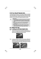
... procedures in position. It is factory-mounted with its edges, and keep away from touching the connectors (Golden Fingers). 21 There is one ASRock SLI/XFire Switch Card factory-mounted on this section. This card served as a switch between the default mode (x8 / x8) and x16... Make sure that allows you should have three identical 3-Way SLITM-ready graphics cards that hold the card in this motherboard. 2.5 SLITM and 3-Way SLITM Operation Guide This motherboard supports NVIDIA® SLITM and 3-Way SLITM (Scalable Link Interface) technology that your power supply unit (PSU) can...
... procedures in position. It is factory-mounted with its edges, and keep away from touching the connectors (Golden Fingers). 21 There is one ASRock SLI/XFire Switch Card factory-mounted on this section. This card served as a switch between the default mode (x8 / x8) and x16... Make sure that allows you should have three identical 3-Way SLITM-ready graphics cards that hold the card in this motherboard. 2.5 SLITM and 3-Way SLITM Operation Guide This motherboard supports NVIDIA® SLITM and 3-Way SLITM (Scalable Link Interface) technology that your power supply unit (PSU) can...
User Manual
Page 27
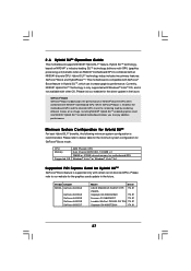
..., based on NVIDIA®' s industry-leading SLITM technology, delivers multi-GPU (graphics processing unit) benefits when an NVIDIA® motherboard GPU is supported only with Windows® VistaTM OS, and is recommended. Vendor Chipset NVIDIA GeForce 8400GS GeForce 8400GS GeForce 8400GS GeForce...website for GeForce® Boost mode. Installing NVIDIA® Hybrid SLITM-enabled graphics card into NVIDIA® Hybrid SLITM-enabled motherboard allows you to below table for the minimum system configuration for the graphics cards update in the future. Minimum System Configuration ...
..., based on NVIDIA®' s industry-leading SLITM technology, delivers multi-GPU (graphics processing unit) benefits when an NVIDIA® motherboard GPU is supported only with Windows® VistaTM OS, and is recommended. Vendor Chipset NVIDIA GeForce 8400GS GeForce 8400GS GeForce 8400GS GeForce...website for GeForce® Boost mode. Installing NVIDIA® Hybrid SLITM-enabled graphics card into NVIDIA® Hybrid SLITM-enabled motherboard allows you to below table for the minimum system configuration for the graphics cards update in the future. Minimum System Configuration ...
User Manual
Page 28
... the setup anymore. However, since this motherboard only support GeForce® Boost mode (Boost Performance), please do not need to enter BIOS setup. Boot your computer. Install Hybrid SLITM driver from our support CD to select your Windows® taskbar. Then you are two ASRock support CD in the following path of...
... the setup anymore. However, since this motherboard only support GeForce® Boost mode (Boost Performance), please do not need to enter BIOS setup. Boot your computer. Install Hybrid SLITM driver from our support CD to select your Windows® taskbar. Then you are two ASRock support CD in the following path of...
User Manual
Page 30
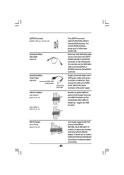
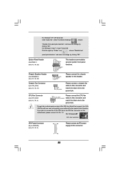
.... Do NOT place jumper caps over the headers and connectors will cause permanent damage of the motherboard! • Floppy Connector (33-pin FLOPPY1) (see p.12, No. 9) PIN1 IDE1 connect the blue end to the motherboard connect the black end to the IDE devices 80-conductor ATA 66/100/133 cable Note: Please...
.... Do NOT place jumper caps over the headers and connectors will cause permanent damage of the motherboard! • Floppy Connector (33-pin FLOPPY1) (see p.12, No. 9) PIN1 IDE1 connect the blue end to the motherboard connect the black end to the IDE devices 80-conductor ATA 66/100/133 cable Note: Please...
User Manual
Page 31
...connect SATAII_6 (PORT5) connector and eSATAII connector. Besides six default USB 2.0 ports on the I/O panel, there are two USB 2.0 headers on this motherboard. Each USB 2.0 header can also use wireless local area network (WLAN) adapter. It allows you to -use the SATA data cable to the SATA... / SATAII hard disk or the SATAII connector on this motherboard. This header supports WiFi+AP function with ASRock WiFi-802.11g or WiFi-802.11n module, an easy-to create a wireless environment and enjoy the convenience of the power supply. The...
...connect SATAII_6 (PORT5) connector and eSATAII connector. Besides six default USB 2.0 ports on the I/O panel, there are two USB 2.0 headers on this motherboard. Each USB 2.0 header can also use wireless local area network (WLAN) adapter. It allows you to -use the SATA data cable to the SATA... / SATAII hard disk or the SATAII connector on this motherboard. This header supports WiFi+AP function with ASRock WiFi-802.11g or WiFi-802.11n module, an easy-to create a wireless environment and enjoy the convenience of the power supply. The...
User Manual
Page 32
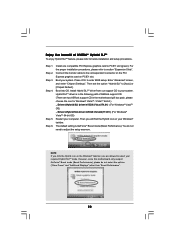
...audio devices. 1. E. Front Panel Audio Header (9-pin HD_AUDIO1) (see p.12, No. 31) CD1 This header supports the Hot Plug detection function for ASRock DeskExpress. Connect Mic_IN (MIC) to function correctly. D. Enter BIOS Setup Utility. High Definition Audio supports Jack Sensing, but the panel wire on the ...) to Ground (GND). Click the icon on the lower right hand taskbar to support one USB 2.0 port. If you use WiFi+AP functin on this motherboard, this picture for AC'97 audio panel. To connect the 4-Pin USB device cable to this header, please refer to this ...
...audio devices. 1. E. Front Panel Audio Header (9-pin HD_AUDIO1) (see p.12, No. 31) CD1 This header supports the Hot Plug detection function for ASRock DeskExpress. Connect Mic_IN (MIC) to function correctly. D. Enter BIOS Setup Utility. High Definition Audio supports Jack Sensing, but the panel wire on the ...) to Ground (GND). Click the icon on the lower right hand taskbar to support one USB 2.0 port. If you use WiFi+AP functin on this motherboard, this picture for AC'97 audio panel. To connect the 4-Pin USB device cable to this header, please refer to this ...
User Manual
Page 33
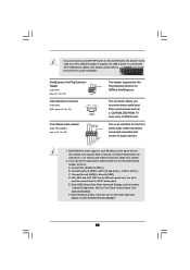
.... 25) Chassis Fan Connector (3-pin CHA_FAN1) (see p.12, No. 8) 12 24 Please connect an ATX power supply to this connector. 1 13 33 Though this motherboard, please connect it to Pin 1-3. For Windows® VistaTM / VistaTM 64-bit OS: Click the right-top "Folder" icon , choose "Disable front panel jack detection...", and save the change by clicking "OK". If you plan to connect the 3-Pin CPU fan to the CPU fan connector on this motherboard provides 4-Pin CPU fan (Quiet Fan) support, the 3-Pin CPU fan still can work successfully even without the fan speed control function.
.... 25) Chassis Fan Connector (3-pin CHA_FAN1) (see p.12, No. 8) 12 24 Please connect an ATX power supply to this connector. 1 13 33 Though this motherboard, please connect it to Pin 1-3. For Windows® VistaTM / VistaTM 64-bit OS: Click the right-top "Folder" icon , choose "Disable front panel jack detection...", and save the change by clicking "OK". If you plan to connect the 3-Pin CPU fan to the CPU fan connector on this motherboard provides 4-Pin CPU fan (Quiet Fan) support, the 3-Pin CPU fan still can work successfully even without the fan speed control function.

