
User Manual
Page 4
...1 1.1 Package Contents 1 1.2 Specifications 2 1.3 Motherboard Layout 5 1.4 I/O Panel 7 Chapter 2 Installation 9 2.1 Installing Memory Modules (SO-DIMM) 10 2.2 Expansion Slot (PCI Express Slot) 12 2.3 Jumpers Setup 13 2.4 Onboard Headers and Connectors 14 Chapter 3 Software and Utilities Operation 18 3.1 Installing Drivers 18 3.2 ASRock Live Update & APP Shop 19 3.2.1 UI Overview 19 3.2.2 Apps 20 3.2.3 BIOS & Drivers 23 3.2.4 Setting 24 Chapter 4 UEFI SETUP UTILITY 25 4.1 Introduction 25 4.1.1 UEFI Menu Bar 25 4.1.2 Navigation Keys 26 4.2 Main Screen 27
...1 1.1 Package Contents 1 1.2 Specifications 2 1.3 Motherboard Layout 5 1.4 I/O Panel 7 Chapter 2 Installation 9 2.1 Installing Memory Modules (SO-DIMM) 10 2.2 Expansion Slot (PCI Express Slot) 12 2.3 Jumpers Setup 13 2.4 Onboard Headers and Connectors 14 Chapter 3 Software and Utilities Operation 18 3.1 Installing Drivers 18 3.2 ASRock Live Update & APP Shop 19 3.2.1 UI Overview 19 3.2.2 Apps 20 3.2.3 BIOS & Drivers 23 3.2.4 Setting 24 Chapter 4 UEFI SETUP UTILITY 25 4.1 Introduction 25 4.1.1 UEFI Menu Bar 25 4.1.2 Navigation Keys 26 4.2 Main Screen 27
User Manual
Page 6
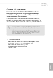
... 4 contains the configuration guide of the software and utilities. Because the motherboard specifications and the BIOS software might be updated, the content of the motherboard and step-by-step installation guides. You may find the latest VGA cards and CPU support list on ASRock's website without notice. In this documentation occur, the updated version will be subject to change without further notice. Chapter 3 contains the operation guide of the BIOS setup. J4125B-ITX J4025B-ITX Chapter 1 Introduction...
... 4 contains the configuration guide of the software and utilities. Because the motherboard specifications and the BIOS software might be updated, the content of the motherboard and step-by-step installation guides. You may find the latest VGA cards and CPU support list on ASRock's website without notice. In this documentation occur, the updated version will be subject to change without further notice. Chapter 3 contains the operation guide of the BIOS setup. J4125B-ITX J4025B-ITX Chapter 1 Introduction...
User Manual
Page 7
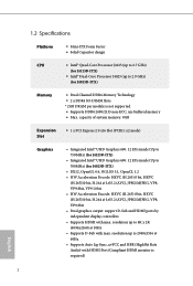
... J4025B-ITX) Memory • Dual Channel DDR4 Memory Technology • 2 x DDR4 SO-DIMM Slots * 2GB DRAM per module is required) English 2 1.2 Specifications Platform • Mini-ITX Form Factor • Solid Capacitor design CPU • Intel® Quad-Core Processor J4125 (up to 2.7 GHz) (for J4125B-ITX) • Intel® Dual-Core Processor J4025 (up to 2048x1536 @ 60Hz • Supports Auto Lip Sync, xvYCC and HBR (High Bit Rate Audio) with HDMI Port (Compliant HDMI monitor is not supported...
... J4025B-ITX) Memory • Dual Channel DDR4 Memory Technology • 2 x DDR4 SO-DIMM Slots * 2GB DRAM per module is required) English 2 1.2 Specifications Platform • Mini-ITX Form Factor • Solid Capacitor design CPU • Intel® Quad-Core Processor J4125 (up to 2.7 GHz) (for J4125B-ITX) • Intel® Dual-Core Processor J4025 (up to 2048x1536 @ 60Hz • Supports Auto Lip Sync, xvYCC and HBR (High Bit Rate Audio) with HDMI Port (Compliant HDMI monitor is not supported...
User Manual
Page 8
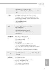
...; 1 x D-Sub Port • 1 x HDMI Port • 1 x USB 2.0 Port (Supports ESD Protection) • 3 x USB 3.2 Gen1 Ports (Supports ESD Protection) • 1 x RJ-45 LAN Port with LED (ACT/LINK LED and SPEED LED) • HD Audio Jacks: Line in / Front Speaker / Microphone Storage • 2 x SATA3 6.0 Gb/s Connectors, support NCQ, AHCI and Hot Plug Connector • 1 x COM Port Header • 1 x Chassis Intrusion and Speaker Header • 1 x CPU Fan Connector (3-pin) • 1 x Chassis Fan Connector (3-pin) • 1 x 24 pin ATX Power Connector • 1 x Front Panel Audio Connector...
...; 1 x D-Sub Port • 1 x HDMI Port • 1 x USB 2.0 Port (Supports ESD Protection) • 3 x USB 3.2 Gen1 Ports (Supports ESD Protection) • 1 x RJ-45 LAN Port with LED (ACT/LINK LED and SPEED LED) • HD Audio Jacks: Line in / Front Speaker / Microphone Storage • 2 x SATA3 6.0 Gb/s Connectors, support NCQ, AHCI and Hot Plug Connector • 1 x COM Port Header • 1 x Chassis Intrusion and Speaker Header • 1 x CPU Fan Connector (3-pin) • 1 x Chassis Fan Connector (3-pin) • 1 x 24 pin ATX Power Connector • 1 x Front Panel Audio Connector...

User Manual
Page 9
... • Supports Plug and Play • ACPI 5.0 compliant wake up events • Supports jumperfree • SMBIOS 3.0 support Hardware Monitor • CPU/Chassis temperature sensing • CPU/Chassis Fan Tachometer • CPU/Chassis Quiet Fan (Auto adjust chassis fan speed by CPU temperature) • CPU/Chassis Fan multi-speed control • CASE OPEN detection • Voltage monitoring: +12V, +5V, +3.3V, CPU Vcore OS • Microsoft® Windows® 10 64-bit * Supports UEFI mode only Certifications • FCC, CE • ErP/EuP ready (ErP/EuP ready power supply is...
... • Supports Plug and Play • ACPI 5.0 compliant wake up events • Supports jumperfree • SMBIOS 3.0 support Hardware Monitor • CPU/Chassis temperature sensing • CPU/Chassis Fan Tachometer • CPU/Chassis Quiet Fan (Auto adjust chassis fan speed by CPU temperature) • CPU/Chassis Fan multi-speed control • CASE OPEN detection • Voltage monitoring: +12V, +5V, +3.3V, CPU Vcore OS • Microsoft® Windows® 10 64-bit * Supports UEFI mode only Certifications • FCC, CE • ErP/EuP ready (ErP/EuP ready power supply is...

User Manual
Page 11
Description 1 CPU Fan Connector (CPU_FAN1) 2 ATX Power Connector (ATXPWR1) 3 System Panel Header (PANEL1) 4 Chassis Intrusion and Speaker Header (SPK_CI1) 5 Clear CMOS Jumper (CLRMOS1) 6 Chassis Fan Connector (CHA_FAN1) 7 2 x 260-pin DDR4 SO-DIMM Slots (DDR4_A1, DDR4_B1) 8 COM Port Header (COM2) 9 USB 2.0 Header (USB4_5) 10 USB 3.2 Gen1 Header (USB3_1_2) 11 USB 2.0 Header (USB2_3) 12 SATA3 Connector (SATA3_1) 13 SATA3 Connector (SATA3_2) 14 Front Panel Audio Header (HD_AUDIO1) 6 English No.
Description 1 CPU Fan Connector (CPU_FAN1) 2 ATX Power Connector (ATXPWR1) 3 System Panel Header (PANEL1) 4 Chassis Intrusion and Speaker Header (SPK_CI1) 5 Clear CMOS Jumper (CLRMOS1) 6 Chassis Fan Connector (CHA_FAN1) 7 2 x 260-pin DDR4 SO-DIMM Slots (DDR4_A1, DDR4_B1) 8 COM Port Header (COM2) 9 USB 2.0 Header (USB4_5) 10 USB 3.2 Gen1 Header (USB3_1_2) 11 USB 2.0 Header (USB2_3) 12 SATA3 Connector (SATA3_1) 13 SATA3 Connector (SATA3_2) 14 Front Panel Audio Header (HD_AUDIO1) 6 English No.
User Manual
Page 14
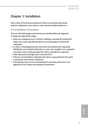
... motherboard settings. • Make sure to the motherboard's components, NEVER place your chassis to the chassis, please do not overtighten the screws! Pre-installation Precautions Take note of the following precautions before you handle the components. • Hold components by the edges and do so may damage the motherboard. 9 English J4125B-ITX J4025B-ITX Chapter 2 Installation This is a Mini-ITX form factor motherboard. Failure...
... motherboard settings. • Make sure to the motherboard's components, NEVER place your chassis to the chassis, please do not overtighten the screws! Pre-installation Precautions Take note of the following precautions before you handle the components. • Hold components by the edges and do so may damage the motherboard. 9 English J4125B-ITX J4025B-ITX Chapter 2 Installation This is a Mini-ITX form factor motherboard. Failure...

User Manual
Page 17
... make sure that the power supply is switched off or the power cord is used for the card before you start the installation. 2.2 Expansion Slot (PCI Express Slot) There is set to "boot from Onboard VGA" as default even the user install a VGA card on the motherboard. Warning: To ensure better graphics compability, the BIOS is 1 PCI Express slot on PCIe slot. 12 English Before installing an expansion card, please make necessary hardware settings for PCI Express x2 lane width cards. PCIe slot: PCIE1 (PCIe 2.0 x16 slot) is unplugged.
... make sure that the power supply is switched off or the power cord is used for the card before you start the installation. 2.2 Expansion Slot (PCI Express Slot) There is set to "boot from Onboard VGA" as default even the user install a VGA card on the motherboard. Warning: To ensure better graphics compability, the BIOS is 1 PCI Express slot on PCIe slot. 12 English Before installing an expansion card, please make necessary hardware settings for PCI Express x2 lane width cards. PCIe slot: PCIE1 (PCIe 2.0 x16 slot) is unplugged.
User Manual
Page 18
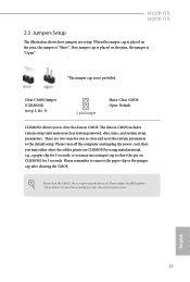
... use a jumper cap to short the pin on CLRMOS1 by using metal material, e.g., a paper clip for 3 seconds; Please remember to clear the record of previous chassis intrusion status. If you to the default setup. Please adjust the BIOS option "Clear Status" to remove the paper clip or the jumper cap after clearing the CMOS. The data in CMOS. Clear CMOS Jumper (CLRMOS1) (see p.5, No. 5) 2-pin Jumper Short: Clear CMOS Open: Default CLRMOS1 allows you clear the CMOS, the case...
... use a jumper cap to short the pin on CLRMOS1 by using metal material, e.g., a paper clip for 3 seconds; Please remember to clear the record of previous chassis intrusion status. If you to the default setup. Please adjust the BIOS option "Clear Status" to remove the paper clip or the jumper cap after clearing the CMOS. The data in CMOS. Clear CMOS Jumper (CLRMOS1) (see p.5, No. 5) 2-pin Jumper Short: Clear CMOS Open: Default CLRMOS1 allows you clear the CMOS, the case...

User Manual
Page 19
... the wire assignments and the pin assignments are NOT jumpers. A front panel module mainly consists of power switch, reset switch, power LED, hard drive activity LED, speaker and etc. 2.4 Onboard Headers and Connectors Onboard headers and connectors are matched correctly. RESET (Reset Switch): Connect to the pin assignments below. System Panel Header (9-pin PANEL1) (see p.5, No. 4) 14 Please connect the chassis intrusion and the chassis speaker to this header according to the reset switch on the chassis front panel. When connecting your system using the power...
... the wire assignments and the pin assignments are NOT jumpers. A front panel module mainly consists of power switch, reset switch, power LED, hard drive activity LED, speaker and etc. 2.4 Onboard Headers and Connectors Onboard headers and connectors are matched correctly. RESET (Reset Switch): Connect to the pin assignments below. System Panel Header (9-pin PANEL1) (see p.5, No. 4) 14 Please connect the chassis intrusion and the chassis speaker to this header according to the reset switch on the chassis front panel. When connecting your system using the power...
User Manual
Page 20
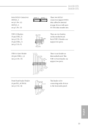
... headers on this motherboard. English 15 J4125B-ITX J4025B-ITX Serial ATA3 Connectors (SATA3_1: see p.5, No. 12) (SATA3_2: see p.5, No. 13) SATA3_2 SATA3_1 These two SATA3 connectors support SATA data cables for connecting audio devices to 6.0 Gb/s data transfer rate. Each USB 2.0 header can support two ports. 1 Vbus IntA_P_SSRXIntA_P_SSRX+ GND IntA_P_SSTXIntA_P_SSTX+ GND IntA_P_DIntA_P_D+ ID Front Panel Audio Header (9-pin HD_AUDIO1) (see p.5, No. 10) IntA_P_D+ IntA_P_DGND IntA_P_SSTX+ IntA_P_SSTXGND IntA_P_SSRX+ IntA_P_SSRXVbus There is for internal storage devices...
... headers on this motherboard. English 15 J4125B-ITX J4025B-ITX Serial ATA3 Connectors (SATA3_1: see p.5, No. 12) (SATA3_2: see p.5, No. 13) SATA3_2 SATA3_1 These two SATA3 connectors support SATA data cables for connecting audio devices to 6.0 Gb/s data transfer rate. Each USB 2.0 header can support two ports. 1 Vbus IntA_P_SSRXIntA_P_SSRX+ GND IntA_P_SSTXIntA_P_SSTX+ GND IntA_P_DIntA_P_D+ ID Front Panel Audio Header (9-pin HD_AUDIO1) (see p.5, No. 10) IntA_P_D+ IntA_P_DGND IntA_P_SSTX+ IntA_P_SSTXGND IntA_P_SSRX+ IntA_P_SSRXVbus There is for internal storage devices...

User Manual
Page 21
... the chassis must support HDA to Ground (GND). To use an AC'97 audio panel, please install it along Pin 1 and Pin 13. Connect Ground (GND) to function correctly. GND +12V CPU_FAN_SPEED Please connect the CPU fan cable to the connector and match the black wire to the front panel audio header by the steps below: A. If you use a 20-pin ATX power supply, please plug it to the ground pin. 12 24 1 13 This motherboard...
... the chassis must support HDA to Ground (GND). To use an AC'97 audio panel, please install it along Pin 1 and Pin 13. Connect Ground (GND) to function correctly. GND +12V CPU_FAN_SPEED Please connect the CPU fan cable to the connector and match the black wire to the front panel audio header by the steps below: A. If you use a 20-pin ATX power supply, please plug it to the ground pin. 12 24 1 13 This motherboard...

User Manual
Page 23
.... Drivers Menu The drivers compatible to install those required drivers. Please click Install All or follow the installation wizard to display the menu. Click on a specific item then follow the order from top to bottom to your system will be auto-detected and listed on the file "ASRSETUP.EXE" in your CD-ROM drive. If the Main Menu does not appear automatically, locate and double click on the support CD driver...
.... Drivers Menu The drivers compatible to install those required drivers. Please click Install All or follow the installation wizard to display the menu. Click on a specific item then follow the order from top to bottom to your system will be auto-detected and listed on the file "ASRSETUP.EXE" in your CD-ROM drive. If the Main Menu does not appear automatically, locate and double click on the support CD driver...

User Manual
Page 30
... UEFI software is constantly being updated, the following selections: Main For setting system time/date information Advanced For advanced system configurations Tool Useful tools H/W Monitor Displays current hardware status Security For security settings Boot For configuring boot settings and boot priority Exit Exit the current screen or the UEFI Setup Utility English 25 J4125B-ITX J4025B-ITX Chapter 4 UEFI SETUP UTILITY 4.1 Introduction This section explains how to use the UEFI SETUP UTILITY to enter the UEFI SETUP UTILITY after you power on the system chassis...
... UEFI software is constantly being updated, the following selections: Main For setting system time/date information Advanced For advanced system configurations Tool Useful tools H/W Monitor Displays current hardware status Security For security settings Boot For configuring boot settings and boot priority Exit Exit the current screen or the UEFI Setup Utility English 25 J4125B-ITX J4025B-ITX Chapter 4 UEFI SETUP UTILITY 4.1 Introduction This section explains how to use the UEFI SETUP UTILITY to enter the UEFI SETUP UTILITY after you power on the system chassis...

User Manual
Page 35
... a primary VGA. Set to Auto to the integrated graphics processor when the system boots up. PCIE1 Link Speed Select the link speed for PCIE1. 30 English The default value is installed. Front Panel Enable/disable front panel HD audio. Share Memory Configure the size of memory that is allocated to enable onboard HD audio and automatically disable it when a sound card is [Auto]. Onboard HD Audio Enable/disable onboard HD audio. 4.3.2 Chipset Configuration DRAM Voltage Use this to configure DRAM Voltage. Onboard LAN Enable or disable the onboard network interface controller.
... a primary VGA. Set to Auto to the integrated graphics processor when the system boots up. PCIE1 Link Speed Select the link speed for PCIE1. 30 English The default value is installed. Front Panel Enable/disable front panel HD audio. Share Memory Configure the size of memory that is allocated to enable onboard HD audio and automatically disable it when a sound card is [Auto]. Onboard HD Audio Enable/disable onboard HD audio. 4.3.2 Chipset Configuration DRAM Voltage Use this to configure DRAM Voltage. Onboard LAN Enable or disable the onboard network interface controller.
User Manual
Page 38
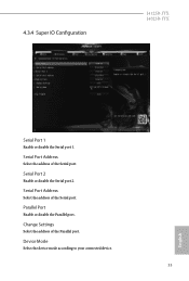
Serial Port Address Select the address of the Parallel port. Change Settings Select the address of the Serial port. Serial Port Address Select the address of the Serial port. Serial Port 2 Enable or disable the Serial port 2. Parallel Port Enable or disable the Parallel port. Device Mode Select the device mode according to your connected device. 33 English 4.3.4 Super IO Configuration J4125B-ITX J4025B-ITX Serial Port 1 Enable or disable the Serial port 1.
Serial Port Address Select the address of the Parallel port. Change Settings Select the address of the Serial port. Serial Port Address Select the address of the Serial port. Serial Port 2 Enable or disable the Serial port 2. Parallel Port Enable or disable the Parallel port. Device Mode Select the device mode according to your connected device. 33 English 4.3.4 Super IO Configuration J4125B-ITX J4025B-ITX Serial Port 1 Enable or disable the Serial port 1.
User Manual
Page 43
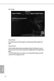
4.4 Tools Instant Flash Save UEFI files in your UEFI. Please setup network configuration before using Internet Flash. *For BIOS backup and recovery purpose, it is recommended to plug in your USB storage device and run Instant Flash to update your USB pen drive before using this function. 38 English Internet Flash ASRock Internet Flash downloads and updates the latest UEFI firmware version from our servers for you.
4.4 Tools Instant Flash Save UEFI files in your UEFI. Please setup network configuration before using Internet Flash. *For BIOS backup and recovery purpose, it is recommended to plug in your USB storage device and run Instant Flash to update your USB pen drive before using this function. 38 English Internet Flash ASRock Internet Flash downloads and updates the latest UEFI firmware version from our servers for you.

User Manual
Page 44
J4125B-ITX J4025B-ITX Internet Setting Enable or disable sound effects in the setup utility. UEFI Download Server Select a server to configure internet connection settings for Internet Flash. Network Configuration Use this to download the UEFI firmware. 39 English
J4125B-ITX J4025B-ITX Internet Setting Enable or disable sound effects in the setup utility. UEFI Download Server Select a server to configure internet connection settings for Internet Flash. Network Configuration Use this to download the UEFI firmware. 39 English

User Manual
Page 45
Chassis Fan 1 Setting This allows you to set CPU fan 1's speed. Configuration options: [Full On], [Automatic Mode] and [Manual]. Case Open Feature Enable or disable Case Open Feature to monitor the status of the hardware on your system, including the parameters of the CPU temperature, motherboard temperature, fan speed and voltage. CPU Fan 1 Setting This allows you to set chassis fan 1's speed. Configuration options: [Full On] and [Automatic Mode]. The default value is [Full On]. 4.5 Hardware Health Event Monitoring Screen This section allows you to detect whether...
Chassis Fan 1 Setting This allows you to set CPU fan 1's speed. Configuration options: [Full On], [Automatic Mode] and [Manual]. Case Open Feature Enable or disable Case Open Feature to monitor the status of the hardware on your system, including the parameters of the CPU temperature, motherboard temperature, fan speed and voltage. CPU Fan 1 Setting This allows you to set chassis fan 1's speed. Configuration options: [Full On] and [Automatic Mode]. The default value is [Full On]. 4.5 Hardware Health Event Monitoring Screen This section allows you to detect whether...

User Manual
Page 46
... UEFI Setup Utility. Leave it blank and press enter to remove the password. Secure Boot Enable to change the supervisor/user password for the system. Disable this section you may also clear the user password. You may set or change the settings in the UEFI Setup Utility. Users are unable to change the password for the administrator account. Leave it blank and press enter to remove the password. User Password Set or change the settings in ME. J4125B-ITX J4025B-ITX 4.6 Security Screen In this option to use...
... UEFI Setup Utility. Leave it blank and press enter to remove the password. Secure Boot Enable to change the supervisor/user password for the system. Disable this section you may also clear the user password. You may set or change the settings in the UEFI Setup Utility. Users are unable to change the password for the administrator account. Leave it blank and press enter to remove the password. User Password Set or change the settings in ME. J4125B-ITX J4025B-ITX 4.6 Security Screen In this option to use...


