
User Manual
Page 4
... Contents 1 1.2 Specifications 2 1.3 Motherboard Layout 5 1.4 I/O Panel 7 Chapter 2 Installation 9 2.1 Installing Memory Modules (DIMM) 10 2.2 Expansion Slots (PCI Express Slots) 12 2.3 Jumpers Setup 13 2.4 Onboard Headers and Connectors 14 Chapter 3 Software and Utilities Operation 18 3.1 Installing Drivers 18 3.2 ASRock Live Update & APP Shop 19 3.2.1 UI Overview 19 3.2.2 Apps 20 3.2.3 BIOS & Drivers 23 3.2.4 Setting 24 3.3 Enabling USB Ports for Windows® 7 Installation 25 Chapter 4 UEFI SETUP UTILITY 28 4.1 Introduction 28 4.1.1 UEFI Menu Bar 28...
... Contents 1 1.2 Specifications 2 1.3 Motherboard Layout 5 1.4 I/O Panel 7 Chapter 2 Installation 9 2.1 Installing Memory Modules (DIMM) 10 2.2 Expansion Slots (PCI Express Slots) 12 2.3 Jumpers Setup 13 2.4 Onboard Headers and Connectors 14 Chapter 3 Software and Utilities Operation 18 3.1 Installing Drivers 18 3.2 ASRock Live Update & APP Shop 19 3.2.1 UI Overview 19 3.2.2 Apps 20 3.2.3 BIOS & Drivers 23 3.2.4 Setting 24 3.3 Enabling USB Ports for Windows® 7 Installation 25 Chapter 4 UEFI SETUP UTILITY 28 4.1 Introduction 28 4.1.1 UEFI Menu Bar 28...
User Manual
Page 6
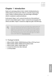
... you for specific information about the model you are using. In this documentation occur, the updated version will be subject to quality and endurance. Chapter 3 contains the operation guide of the BIOS setup. ASRock website http://www.asrock.com. 1.1 Package Contents • ASRock J3710M / J3160M / J3060M Motherboard (Micro ATX Form Factor) • ASRock J3710M / J3160M / J3060M Quick Installation Guide • ASRock J3710M / J3160M / J3060M Support CD • 2 x Serial ATA (SATA) Data Cables (Optional) • 1 x I/O Panel Shield...
... you for specific information about the model you are using. In this documentation occur, the updated version will be subject to quality and endurance. Chapter 3 contains the operation guide of the BIOS setup. ASRock website http://www.asrock.com. 1.1 Package Contents • ASRock J3710M / J3160M / J3060M Motherboard (Micro ATX Form Factor) • ASRock J3710M / J3160M / J3060M Quick Installation Guide • ASRock J3710M / J3160M / J3060M Support CD • 2 x Serial ATA (SATA) Data Cables (Optional) • 1 x I/O Panel Shield...

User Manual
Page 7
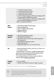
... Slot • 1 x PCI Express 2.0 x16 Slot (PCIE2 @ x1 mode) • 2 x PCI Express 2.0 x1 Slots Graphics • Integrated Intel® HD Graphics 405: 16 EUs inside (Up to 740MHz) (for J3710M) • Integrated Intel® HD Graphics 400: 12 EUs inside (Up to 1920x1200 @ 60Hz • Supports Auto Lip Sync, xvYCC and HBR (High Bit Rate Audio) with max. resolution up to 700MHz) (for J3060M) Memory • Dual Channel DDR3/DDR3L Memory Technology...
... Slot • 1 x PCI Express 2.0 x16 Slot (PCIE2 @ x1 mode) • 2 x PCI Express 2.0 x1 Slots Graphics • Integrated Intel® HD Graphics 405: 16 EUs inside (Up to 740MHz) (for J3710M) • Integrated Intel® HD Graphics 400: 12 EUs inside (Up to 1920x1200 @ 60Hz • Supports Auto Lip Sync, xvYCC and HBR (High Bit Rate Audio) with max. resolution up to 700MHz) (for J3060M) Memory • Dual Channel DDR3/DDR3L Memory Technology...

User Manual
Page 8
... Port • 1 x PS/2 Keyboard Port • 1 x D-Sub Port • 1 x DVI-D Port • 1 x HDMI Port • 2 x USB 2.0 Ports (Supports ESD Protection (ASRock Full Spike Protection)) • 2 x USB 3.0 Ports (Supports ESD Protection (ASRock Full Spike Protection)) • 1 x RJ-45 LAN Port with LED (ACT/LINK LED and SPEED LED) • HD Audio Jacks: Line in / Front Speaker / Microphone Storage • 2 x SATA3 6.0 Gb/s Connectors, support NCQ, AHCI and Hot Plug English Connector • 1 x Print Port Header • 2 x COM Port Headers • 1 x TPM Header • 1 x Chassis...
... Port • 1 x PS/2 Keyboard Port • 1 x D-Sub Port • 1 x DVI-D Port • 1 x HDMI Port • 2 x USB 2.0 Ports (Supports ESD Protection (ASRock Full Spike Protection)) • 2 x USB 3.0 Ports (Supports ESD Protection (ASRock Full Spike Protection)) • 1 x RJ-45 LAN Port with LED (ACT/LINK LED and SPEED LED) • HD Audio Jacks: Line in / Front Speaker / Microphone Storage • 2 x SATA3 6.0 Gb/s Connectors, support NCQ, AHCI and Hot Plug English Connector • 1 x Print Port Header • 2 x COM Port Headers • 1 x TPM Header • 1 x Chassis...
User Manual
Page 9
...power supply is required. Please refer to utilize the memory that Windows® cannot use. 4 J3710M J3160M J3060M • 1 x CPU Fan Connector (3-pin) • 1 x Chassis Fan Connector (3-pin) • 1 x 24 pin ATX Power Connector • 1 x Front Panel Audio Connector • 2 x USB 2.0 Headers (Support 4 USB 2.0 ports) (Supports ESD Protection (ASRock Full Spike Protection)) • 1 x USB 3.0 Header (Supports 2 USB 3.0 ports) (Supports ESD Protection (ASRock Full Spike Protection)) * USB3_2_3 is shared with GUI support • Supports Plug and Play • ACPI 5.0 compliant wake...
...power supply is required. Please refer to utilize the memory that Windows® cannot use. 4 J3710M J3160M J3060M • 1 x CPU Fan Connector (3-pin) • 1 x Chassis Fan Connector (3-pin) • 1 x 24 pin ATX Power Connector • 1 x Front Panel Audio Connector • 2 x USB 2.0 Headers (Support 4 USB 2.0 ports) (Supports ESD Protection (ASRock Full Spike Protection)) • 1 x USB 3.0 Header (Supports 2 USB 3.0 ports) (Supports ESD Protection (ASRock Full Spike Protection)) * USB3_2_3 is shared with GUI support • Supports Plug and Play • ACPI 5.0 compliant wake...

User Manual
Page 14
... injuries to you uninstall any motherboard settings. • Make sure to use a grounded wrist strap or touch a safety grounded object before installing or removing the motherboard. Pre-installation Precautions Take note of your chassis to ensure that comes with the components. • When placing screws to secure the motherboard to the motherboard's components, NEVER place your motherboard directly on a grounded anti...
... injuries to you uninstall any motherboard settings. • Make sure to use a grounded wrist strap or touch a safety grounded object before installing or removing the motherboard. Pre-installation Precautions Take note of your chassis to ensure that comes with the components. • When placing screws to secure the motherboard to the motherboard's components, NEVER place your motherboard directly on a grounded anti...
User Manual
Page 17
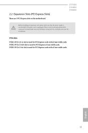
... Slots (PCI Express Slots) There are 3 PCI Express slots on the motherboard. PCIe slots: PCIE1 (PCIe 2.0 x1 slot) is unplugged. English 12 Please read the documentation of the expansion card and make sure that the power supply is switched off or the power cord is used for the card before you start the installation. J3710M J3160M J3060M Before installing an expansion card, please make necessary hardware settings for PCI Express cards with x1 lane width cards. PCIE3 (PCIe 2.0 x1 slot) is used...
... Slots (PCI Express Slots) There are 3 PCI Express slots on the motherboard. PCIe slots: PCIE1 (PCIe 2.0 x1 slot) is unplugged. English 12 Please read the documentation of the expansion card and make sure that the power supply is switched off or the power cord is used for the card before you start the installation. J3710M J3160M J3060M Before installing an expansion card, please make necessary hardware settings for PCI Express cards with x1 lane width cards. PCIE3 (PCIe 2.0 x1 slot) is used...

User Manual
Page 18
... on the pins, the jumper is removed. To clear and reset the system parameters to clear the CMOS when you just finish updating the BIOS, you must boot up the system first, and then shut it down before you need to default setup, please turn off the computer and unplug the power cord from the power supply. After waiting for 15 seconds, use a jumper cap to short pin2 and...
... on the pins, the jumper is removed. To clear and reset the system parameters to clear the CMOS when you just finish updating the BIOS, you must boot up the system first, and then shut it down before you need to default setup, please turn off the computer and unplug the power cord from the power supply. After waiting for 15 seconds, use a jumper cap to short pin2 and...

User Manual
Page 19
... is in S1/S3 sleep state. A front panel module mainly consists of power switch, reset switch, power LED, hard drive activity LED, speaker and etc. You may differ by chassis. Note the positive and negative pins before connecting the cables. HDLED (Hard Drive Activity LED): Connect to this header according to the power switch on when the system is reading or writing data. When connecting your system using the power switch. 2.4 Onboard Headers and Connectors J3710M J3160M J3060M Onboard headers and connectors are matched correctly...
... is in S1/S3 sleep state. A front panel module mainly consists of power switch, reset switch, power LED, hard drive activity LED, speaker and etc. You may differ by chassis. Note the positive and negative pins before connecting the cables. HDLED (Hard Drive Activity LED): Connect to this header according to the power switch on when the system is reading or writing data. When connecting your system using the power switch. 2.4 Onboard Headers and Connectors J3710M J3160M J3060M Onboard headers and connectors are matched correctly...
User Manual
Page 21
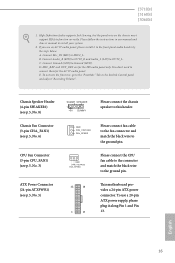
... the black wire to MIC2_L. To use an AC'97 audio panel, please install it along Pin 1 and Pin 13. C. Connect Mic_IN (MIC) to the ground pin. E. GND FAN_VOLTAGE FAN_SPEED Please connect the CPU fan cable to the connector and match the black wire to function correctly. D. High Definition Audio supports Jack Sensing, but the panel wire on the chassis must support HDA to the ground pin. 12 24 1 13 This motherboard provides a 24-pin ATX power connector.
... the black wire to MIC2_L. To use an AC'97 audio panel, please install it along Pin 1 and Pin 13. C. Connect Mic_IN (MIC) to the ground pin. E. GND FAN_VOLTAGE FAN_SPEED Please connect the CPU fan cable to the connector and match the black wire to function correctly. D. High Definition Audio supports Jack Sensing, but the panel wire on the chassis must support HDA to the ground pin. 12 24 1 13 This motherboard provides a 24-pin ATX power connector.

User Manual
Page 23
... install it. Drivers Menu The drivers compatible to your system will be auto-detected and listed on a specific item then follow the order from top to bottom to install those required drivers. Therefore, the drivers you install can work properly. Click on the support CD driver page. If the Main Menu does not appear automatically, locate and double click on the file "ASRSETUP.EXE" in your CD-ROM drive. Running The Support...
... install it. Drivers Menu The drivers compatible to your system will be auto-detected and listed on a specific item then follow the order from top to bottom to install those required drivers. Therefore, the drivers you install can work properly. Click on the support CD driver page. If the Main Menu does not appear automatically, locate and double click on the file "ASRSETUP.EXE" in your CD-ROM drive. Running The Support...

User Manual
Page 24
... Panel: The information panel in the center displays data about the currently selected category and allows users to date simply with a few clicks. With ASRock Live Update & APP Shop, you can quickly and easily install various apps and support utilities, such as USB Key, XFast LAN, XFast RAM and more . 19 English Click on your desktop to access ASRock Live Update & APP Shop *You need to be connected...
... Panel: The information panel in the center displays data about the currently selected category and allows users to date simply with a few clicks. With ASRock Live Update & APP Shop, you can quickly and easily install various apps and support utilities, such as USB Key, XFast LAN, XFast RAM and more . 19 English Click on your desktop to access ASRock Live Update & APP Shop *You need to be connected...
User Manual
Page 30
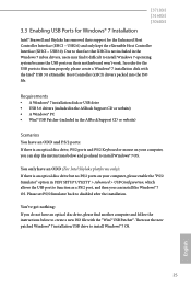
... a Windows® 7 installation disk with the "Win7 USB Patcher". USB2.0) and only kept the eXtensible Host Controller Interface (XHCI - Then use the new patched Windows® 7 installation USB drive to disabled after the installation. 3.3 Enabling USB Ports for Windows® 7 Installation J3710M J3160M J3060M Intel® Braswell and Skylake has removed their motherboard won't work. Please set PS/S Simulator back to install Windows® 7 OS. Requirements • A Windows® 7 installation disk or USB drive • USB 3.0 drivers (included in the ASRock Support CD...
... a Windows® 7 installation disk with the "Win7 USB Patcher". USB2.0) and only kept the eXtensible Host Controller Interface (XHCI - Then use the new patched Windows® 7 installation USB drive to disabled after the installation. 3.3 Enabling USB Ports for Windows® 7 Installation J3710M J3160M J3060M Intel® Braswell and Skylake has removed their motherboard won't work. Please set PS/S Simulator back to install Windows® 7 OS. Requirements • A Windows® 7 installation disk or USB drive • USB 3.0 drivers (included in the ASRock Support CD...
User Manual
Page 31
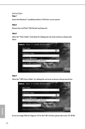
Instructions Step 1 Insert the Windows® 7 installation disk or USB drive to your CD-ROM. 26 English Step 3 Select the "Win7 Folder" from Step1 by clicking the red circle as shown as the picture below . Step 4 Select the "USB Driver Folder" by clicking the red circle as shown as the picture below . Step 2 Extract the tool (Win7 USB Patcher) and launch it. If you are using ASRock's Support CD for the USB 3.0 driver, please select your system.
Instructions Step 1 Insert the Windows® 7 installation disk or USB drive to your CD-ROM. 26 English Step 3 Select the "Win7 Folder" from Step1 by clicking the red circle as shown as the picture below . Step 4 Select the "USB Driver Folder" by clicking the red circle as shown as the picture below . Step 2 Extract the tool (Win7 USB Patcher) and launch it. If you are using ASRock's Support CD for the USB 3.0 driver, please select your system.

User Manual
Page 33
... the reset button on the system chassis. You may not exactly match what you wish to configure your screen. 4.1.1 UEFI Menu Bar The top of the screen has a menu bar with its test routines. If you see on your system. Because the UEFI software is constantly being updated, the following selections: Main For setting system time/date information Advanced For advanced system configurations Tool Useful tools H/W Monitor Displays...
... the reset button on the system chassis. You may not exactly match what you wish to configure your screen. 4.1.1 UEFI Menu Bar The top of the screen has a menu bar with its test routines. If you see on your system. Because the UEFI software is constantly being updated, the following selections: Main For setting system time/date information Advanced For advanced system configurations Tool Useful tools H/W Monitor Displays...

User Manual
Page 39
... HD audio. Primary Graphics Adapter Select a primary VGA. Front Panel Enable/disable front panel HD audio. Share Memory Configure the size of memory that is installed. Onboard HDMI HD Audio Enable audio for the onboard digital outputs. Set to Auto to enable onboard HD audio and automatically disable it when a sound card is allocated to configure DRAM Voltage. The default value is [Auto]. 4.3.2 Chipset Configuration DRAM Voltage Use this to the integrated graphics processor when the system boots up. Onboard LAN Enable or disable the onboard network interface controller. 34...
... HD audio. Primary Graphics Adapter Select a primary VGA. Front Panel Enable/disable front panel HD audio. Share Memory Configure the size of memory that is installed. Onboard HDMI HD Audio Enable audio for the onboard digital outputs. Set to Auto to enable onboard HD audio and automatically disable it when a sound card is allocated to configure DRAM Voltage. The default value is [Auto]. 4.3.2 Chipset Configuration DRAM Voltage Use this to the integrated graphics processor when the system boots up. Onboard LAN Enable or disable the onboard network interface controller. 34...

User Manual
Page 43
Device Mode Select the device mode according to your connected device. 38 English Serial Port Address Select the address of the Parallel port. Parallel Port Enable or disable the Parallel port. Change Settings Select the address of the Serial port. 4.3.5 Super IO Configuration Serial Port 1 Enable or disable the Serial port 1. Serial Port Address Select the address of the Serial port. Serial Port 2 Enable or disable the Serial port 2.
Device Mode Select the device mode according to your connected device. 38 English Serial Port Address Select the address of the Parallel port. Parallel Port Enable or disable the Parallel port. Change Settings Select the address of the Serial port. 4.3.5 Super IO Configuration Serial Port 1 Enable or disable the Serial port 1. Serial Port Address Select the address of the Serial port. Serial Port 2 Enable or disable the Serial port 2.
User Manual
Page 48
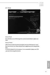
Please setup network configuration before using Internet Flash. *For BIOS backup and recovery purpose, it is recommended to plug in your USB storage device and run Instant Flash to update your USB pen drive before using this function. 43 English Internet Flash ASRock Internet Flash downloads and updates the latest UEFI firmware version from our servers for you. 4.4 Tools J3710M J3160M J3060M Instant Flash Save UEFI files in your UEFI.
Please setup network configuration before using Internet Flash. *For BIOS backup and recovery purpose, it is recommended to plug in your USB storage device and run Instant Flash to update your USB pen drive before using this function. 43 English Internet Flash ASRock Internet Flash downloads and updates the latest UEFI firmware version from our servers for you. 4.4 Tools J3710M J3160M J3060M Instant Flash Save UEFI files in your UEFI.

User Manual
Page 49
Network Configuration Use this to download the UEFI firmware. 44 English UEFI Download Server Select a server to configure internet connection settings for Internet Flash. Internet Setting Enable or disable sound effects in the setup utility.
Network Configuration Use this to download the UEFI firmware. 44 English UEFI Download Server Select a server to configure internet connection settings for Internet Flash. Internet Setting Enable or disable sound effects in the setup utility.
User Manual
Page 50
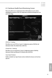
Configuration options: [Full On] and [Automatic Mode]. The default value is [Full On]. The default value is [Full On]. Case Open Feature Enable or disable Case Open Feature to monitor the status of the hardware on your system, including the parameters of the CPU temperature, motherboard temperature, fan speed and voltage. Chassis Fan 1 Setting This allows you to set CPU fan 1's speed. CPU Fan 1 Setting This allows you to set chassis fan 1's speed. Configuration options: [Full On], [Automatic Mode] and [Manual]. 4.5 Hardware Health Event Monitoring Screen J3710M J3160M ...
Configuration options: [Full On] and [Automatic Mode]. The default value is [Full On]. The default value is [Full On]. Case Open Feature Enable or disable Case Open Feature to monitor the status of the hardware on your system, including the parameters of the CPU temperature, motherboard temperature, fan speed and voltage. Chassis Fan 1 Setting This allows you to set CPU fan 1's speed. CPU Fan 1 Setting This allows you to set chassis fan 1's speed. Configuration options: [Full On], [Automatic Mode] and [Manual]. 4.5 Hardware Health Event Monitoring Screen J3710M J3160M ...


