
User Manual
Page 4
... Contents 1 1.2 Specifications 2 1.3 Motherboard Layout 5 1.4 I/O Panel 7 Chapter 2 Installation 9 2.1 Installing Memory Modules (SO-DIMM) 10 2.2 Expansion Slots (PCI Express Slot) 12 2.3 Jumpers Setup 13 2.4 Onboard Headers and Connectors 14 Chapter 3 Software and Utilities Operation 18 3.1 Installing Drivers 18 3.2 ASRock Live Update & APP Shop 19 3.2.1 UI Overview 19 3.2.2 Apps 20 3.2.3 BIOS & Drivers 23 3.2.4 Setting 24 3.3 Enabling USB Ports for Windows® 7 Installation 25 Chapter 4 UEFI SETUP UTILITY 28 4.1 Introduction 28 4.1.1 UEFI Menu Bar 28...
... Contents 1 1.2 Specifications 2 1.3 Motherboard Layout 5 1.4 I/O Panel 7 Chapter 2 Installation 9 2.1 Installing Memory Modules (SO-DIMM) 10 2.2 Expansion Slots (PCI Express Slot) 12 2.3 Jumpers Setup 13 2.4 Onboard Headers and Connectors 14 Chapter 3 Software and Utilities Operation 18 3.1 Installing Drivers 18 3.2 ASRock Live Update & APP Shop 19 3.2.1 UI Overview 19 3.2.2 Apps 20 3.2.3 BIOS & Drivers 23 3.2.4 Setting 24 3.3 Enabling USB Ports for Windows® 7 Installation 25 Chapter 4 UEFI SETUP UTILITY 28 4.1 Introduction 28 4.1.1 UEFI Menu Bar 28...
User Manual
Page 6
... documentation occur, the updated version will be available on ASRock's website as well. You may find the latest VGA cards and CPU support list on ASRock's website without notice. Chapter 3 contains the operation guide of the software and utilities. ASRock website http://www.asrock.com. 1.1 Package Contents • ASRock J3160B-ITX / J3060B-ITX Motherboard (Mini-ITX Form Factor) • ASRock J3160B-ITX / J3060B-ITX Quick Installation Guide • ASRock J3160B-ITX / J3060B-ITX Support CD • 2 x Serial ATA (SATA) Data Cables (Optional) • 1 x I/O Panel Shield 1 English...
... documentation occur, the updated version will be available on ASRock's website as well. You may find the latest VGA cards and CPU support list on ASRock's website without notice. Chapter 3 contains the operation guide of the software and utilities. ASRock website http://www.asrock.com. 1.1 Package Contents • ASRock J3160B-ITX / J3060B-ITX Motherboard (Mini-ITX Form Factor) • ASRock J3160B-ITX / J3060B-ITX Quick Installation Guide • ASRock J3160B-ITX / J3060B-ITX Support CD • 2 x Serial ATA (SATA) Data Cables (Optional) • 1 x I/O Panel Shield 1 English...
User Manual
Page 7
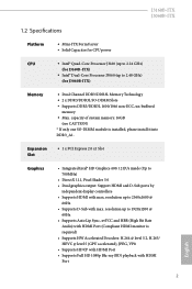
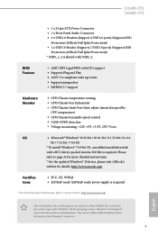
...; Supports Auto Lip Sync, xvYCC and HBR (High Bit Rate Audio) with max. Expansion Slot • 1 x PCI Express 2.0 x1 Slot Graphics • Integrated Intel® HD Graphics 400: 12 EUs inside (Up to 2560x1600 @ 60Hz • Supports D-Sub with HDMI Port English 2 J3160B-ITX J3060B-ITX 1.2 Specifications Platform • Mini-ITX Form Factor • Solid Capacitor for CPU power CPU • Intel® Quad-Core Processor J3160 (up to 2.24 GHz) (for J3060B-ITX) Memory • Dual Channel DDR3/DDR3L Memory Technology...
...; Supports Auto Lip Sync, xvYCC and HBR (High Bit Rate Audio) with max. Expansion Slot • 1 x PCI Express 2.0 x1 Slot Graphics • Integrated Intel® HD Graphics 400: 12 EUs inside (Up to 2560x1600 @ 60Hz • Supports D-Sub with HDMI Port English 2 J3160B-ITX J3060B-ITX 1.2 Specifications Platform • Mini-ITX Form Factor • Solid Capacitor for CPU power CPU • Intel® Quad-Core Processor J3160 (up to 2.24 GHz) (for J3060B-ITX) Memory • Dual Channel DDR3/DDR3L Memory Technology...
User Manual
Page 8
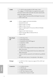
...1 x D-Sub Port • 1 x HDMI Port • 2 x USB 2.0 Ports (Supports ESD Protection (ASRock Full Spike Protection)) • 2 x USB 3.0 Ports (Supports ESD Protection (ASRock Full Spike Protection)) • 1 x RJ-45 LAN Port with LED (ACT/LINK LED and SPEED LED) • HD Audio Jacks: Line in / Front Speaker / Microphone Storage • 2 x SATA3 6.0 Gb/s Connectors, support NCQ, AHCI and Hot Plug English Connector • 1 x COM Port Header • 1 x TPM Header • 1 x Chassis Intrusion Header • 1 x CPU Fan Connector (3-pin) • 1 x Chassis Fan Connector (3-pin) 3
...1 x D-Sub Port • 1 x HDMI Port • 2 x USB 2.0 Ports (Supports ESD Protection (ASRock Full Spike Protection)) • 2 x USB 3.0 Ports (Supports ESD Protection (ASRock Full Spike Protection)) • 1 x RJ-45 LAN Port with LED (ACT/LINK LED and SPEED LED) • HD Audio Jacks: Line in / Front Speaker / Microphone Storage • 2 x SATA3 6.0 Gb/s Connectors, support NCQ, AHCI and Hot Plug English Connector • 1 x COM Port Header • 1 x TPM Header • 1 x Chassis Intrusion Header • 1 x CPU Fan Connector (3-pin) • 1 x Chassis Fan Connector (3-pin) 3
User Manual
Page 9
... ISO file is required. Please refer to page 25 for more detailed instructions. * For the updated Windows® 10 driver, please visit ASRock's website for system usage under Windows® 32-bit operating systems. Windows® 64-bit operating systems do not have such limitations. You can use ASRock XFast RAM to utilize the memory that Windows® cannot use. 4 English J3160B-ITX J3060B-ITX • 1 x 24 pin ATX Power Connector • 1 x Front Panel Audio Connector • 2 x USB 2.0 Headers (Support 4 USB 2.0 ports) (Supports...
... ISO file is required. Please refer to page 25 for more detailed instructions. * For the updated Windows® 10 driver, please visit ASRock's website for system usage under Windows® 32-bit operating systems. Windows® 64-bit operating systems do not have such limitations. You can use ASRock XFast RAM to utilize the memory that Windows® cannot use. 4 English J3160B-ITX J3060B-ITX • 1 x 24 pin ATX Power Connector • 1 x Front Panel Audio Connector • 2 x USB 2.0 Headers (Support 4 USB 2.0 ports) (Supports...
User Manual
Page 10
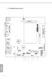
PS2 Mouse PS2 Keyboard COM1 AT X P W R 1 DDR3_B1 VGA1 1.3 Motherboard Layout CPU_FAN1 DDR3_A1 PARALLEL PORT HDMI1 USB 2.0 T: USB0 B: USB1 CMOS Battery USB 3.0 LAN T: USB3 Top: RJ-45 B: USB4 AUDIO CODEC Super I/O HD_AUDIO1 1 PCIE1 COM2 1 CLRMOS1 1 BIOS ROM CI1 1 TPMS1 1 SATA3_2 SPEAKER1 1 SATA3_1 PLED PWRBTN 1 HDLED RESET PANEL1 USB3_1_2 USB2_3 1 USB4_5 1 RoHS Front USB 3.0 Top: LINE IN Center: FRONT Bottom: MIC IN English 5
PS2 Mouse PS2 Keyboard COM1 AT X P W R 1 DDR3_B1 VGA1 1.3 Motherboard Layout CPU_FAN1 DDR3_A1 PARALLEL PORT HDMI1 USB 2.0 T: USB0 B: USB1 CMOS Battery USB 3.0 LAN T: USB3 Top: RJ-45 B: USB4 AUDIO CODEC Super I/O HD_AUDIO1 1 PCIE1 COM2 1 CLRMOS1 1 BIOS ROM CI1 1 TPMS1 1 SATA3_2 SPEAKER1 1 SATA3_1 PLED PWRBTN 1 HDLED RESET PANEL1 USB3_1_2 USB2_3 1 USB4_5 1 RoHS Front USB 3.0 Top: LINE IN Center: FRONT Bottom: MIC IN English 5
User Manual
Page 17
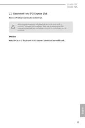
PCIe slot: PCIE1 (PCIe 2.0 x1 slot) is unplugged. English 12 J3160B-ITX J3060B-ITX Before installing an expansion card, please make necessary hardware settings for PCI Express cards with x1 lane width cards. 2.2 Expansion Slots (PCI Express Slot) There is 1 PCI Express slot on the motherboard. Please read the documentation of the expansion card and make sure that the power supply is switched off or the power cord is used for the card before you start the installation.
PCIe slot: PCIE1 (PCIe 2.0 x1 slot) is unplugged. English 12 J3160B-ITX J3060B-ITX Before installing an expansion card, please make necessary hardware settings for PCI Express cards with x1 lane width cards. 2.2 Expansion Slots (PCI Express Slot) There is 1 PCI Express slot on the motherboard. Please read the documentation of the expansion card and make sure that the power supply is switched off or the power cord is used for the card before you start the installation.
User Manual
Page 18
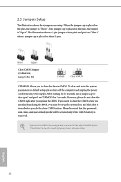
... clear the CMOS, the case open may be cleared only if the CMOS battery is placed on the pins, the jumper is "Open". To clear and reset the system parameters to clear the record of previous chassis intrusion status. Please adjust the BIOS option "Clear Status" to default setup, please turn off the computer and unplug the power cord from the power supply. Please be noted that the password, date, time, and user default...
... clear the CMOS, the case open may be cleared only if the CMOS battery is placed on the pins, the jumper is "Open". To clear and reset the system parameters to clear the record of previous chassis intrusion status. Please adjust the BIOS option "Clear Status" to default setup, please turn off the computer and unplug the power cord from the power supply. Please be noted that the password, date, time, and user default...
User Manual
Page 19
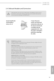
... reset switch on the chassis front panel. RESET (Reset Switch): Connect to the motherboard. HDLED (Hard Drive Activity LED): Connect to this header, make sure the wire assignments and the pin assignments are NOT jumpers. 2.4 Onboard Headers and Connectors J3160B-ITX J3060B-ITX Onboard headers and connectors are matched correctly. System Panel Header (9-pin PANEL1) (see p.5, No. 9) PLED+ PLEDPWRBTN# GND 1 GND RESET# GND HDLEDHDLED+ Connect the power switch, reset switch and system status indicator on the chassis to the hard drive activity LED on the chassis front panel...
... reset switch on the chassis front panel. RESET (Reset Switch): Connect to the motherboard. HDLED (Hard Drive Activity LED): Connect to this header, make sure the wire assignments and the pin assignments are NOT jumpers. 2.4 Onboard Headers and Connectors J3160B-ITX J3060B-ITX Onboard headers and connectors are matched correctly. System Panel Header (9-pin PANEL1) (see p.5, No. 9) PLED+ PLEDPWRBTN# GND 1 GND RESET# GND HDLEDHDLED+ Connect the power switch, reset switch and system status indicator on the chassis to the hard drive activity LED on the chassis front panel...
User Manual
Page 21
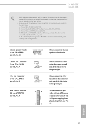
... install it along Pin 1 and Pin 13. J3160B-ITX J3060B-ITX 1. B. This motherboard provides a 24-pin ATX power connector. English 16 You don't need to the ground pin. Please connect fan cable to the fan connector and match the black wire to connect them for the HD audio panel only. If you use a 20-pin ATX power supply, please plug it to install your system. 2. Connect Audio_R (RIN) to OUT2_R and Audio_L (LIN) to this header. Chassis Speaker Header (4-pin SPEAKER1) (see p.5, No. 11) Chassis Fan Connector (3-pin...
... install it along Pin 1 and Pin 13. J3160B-ITX J3060B-ITX 1. B. This motherboard provides a 24-pin ATX power connector. English 16 You don't need to the ground pin. Please connect fan cable to the fan connector and match the black wire to connect them for the HD audio panel only. If you use a 20-pin ATX power supply, please plug it to install your system. 2. Connect Audio_R (RIN) to OUT2_R and Audio_L (LIN) to this header. Chassis Speaker Header (4-pin SPEAKER1) (see p.5, No. 11) Chassis Fan Connector (3-pin...
User Manual
Page 23
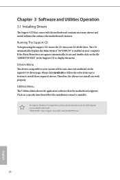
... installation wizard to install those required drivers. Therefore, the drivers you install can work properly. "KB2720599": http://support.microsoft.com/kb/2720599/en-us 18 English To improve Windows 7 compatibility, please download and install the following hot fix provided by Microsoft. Utilities Menu The Utilities Menu shows the application software that enhance the motherboard's features. Click on the file "ASRSETUP.EXE" in your CD-ROM drive. Chapter 3 Software and Utilities Operation 3.1 Installing Drivers The Support...
... installation wizard to install those required drivers. Therefore, the drivers you install can work properly. "KB2720599": http://support.microsoft.com/kb/2720599/en-us 18 English To improve Windows 7 compatibility, please download and install the following hot fix provided by Microsoft. Utilities Menu The Utilities Menu shows the application software that enhance the motherboard's features. Click on the file "ASRSETUP.EXE" in your CD-ROM drive. Chapter 3 Software and Utilities Operation 3.1 Installing Drivers The Support...
User Manual
Page 24
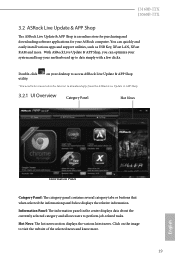
J3160B-ITX J3060B-ITX 3.2 ASRock Live Update & APP Shop The ASRock Live Update & APP Shop is an online store for purchasing and downloading software applications for your motherboard up to date simply with a few clicks. With ASRock Live Update & APP Shop, you can quickly and easily install various apps and support utilities, such as USB Key, XFast LAN, XFast RAM and more . 19 English on the image to visit the...
J3160B-ITX J3060B-ITX 3.2 ASRock Live Update & APP Shop The ASRock Live Update & APP Shop is an online store for purchasing and downloading software applications for your motherboard up to date simply with a few clicks. With ASRock Live Update & APP Shop, you can quickly and easily install various apps and support utilities, such as USB Key, XFast LAN, XFast RAM and more . 19 English on the image to visit the...
User Manual
Page 30
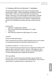
.../2 Simulator" option in the ASRock Support CD or website) Scenarios You have an ODD (For Intel Skylake platforms only): If there is not included in the Windows 7 inbox drivers, users may find another computer and follow the instructions below to install Windows® 7 OS. 25 English J3160B-ITX J3060B-ITX 3.3 Enabling USB Ports for Windows® 7 Installation Intel® Braswell and Skylake has removed their motherboard won't work. Please set PS...
.../2 Simulator" option in the ASRock Support CD or website) Scenarios You have an ODD (For Intel Skylake platforms only): If there is not included in the Windows 7 inbox drivers, users may find another computer and follow the instructions below to install Windows® 7 OS. 25 English J3160B-ITX J3060B-ITX 3.3 Enabling USB Ports for Windows® 7 Installation Intel® Braswell and Skylake has removed their motherboard won't work. Please set PS...
User Manual
Page 31
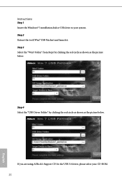
Step 4 Select the "USB Driver Folder" by clicking the red circle as shown as the picture below . Step 2 Extract the tool (Win7 USB Patcher) and launch it. If you are using ASRock's Support CD for the USB 3.0 driver, please select your system. Step 3 Select the "Win7 Folder" from Step1 by clicking the red circle as shown as the picture below . Instructions Step 1 Insert the Windows® 7 installation disk or USB drive to your CD-ROM. 26 English
Step 4 Select the "USB Driver Folder" by clicking the red circle as shown as the picture below . Step 2 Extract the tool (Win7 USB Patcher) and launch it. If you are using ASRock's Support CD for the USB 3.0 driver, please select your system. Step 3 Select the "Win7 Folder" from Step1 by clicking the red circle as shown as the picture below . Instructions Step 1 Insert the Windows® 7 installation disk or USB drive to your CD-ROM. 26 English
User Manual
Page 33
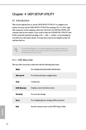
... the UEFI software is constantly being updated, the following selections: Main For setting system time/date information Advanced For advanced system configurations Tool Useful tools H/W Monitor Displays current hardware status Security For security settings Boot For configuring boot settings and boot priority Exit Exit the current screen or the UEFI Setup Utility English 28 Chapter 4 UEFI SETUP UTILITY 4.1 Introduction This section explains how to use the UEFI SETUP UTILITY to enter the UEFI SETUP UTILITY after you wish to configure your screen. 4.1.1 UEFI Menu...
... the UEFI software is constantly being updated, the following selections: Main For setting system time/date information Advanced For advanced system configurations Tool Useful tools H/W Monitor Displays current hardware status Security For security settings Boot For configuring boot settings and boot priority Exit Exit the current screen or the UEFI Setup Utility English 28 Chapter 4 UEFI SETUP UTILITY 4.1 Introduction This section explains how to use the UEFI SETUP UTILITY to enter the UEFI SETUP UTILITY after you wish to configure your screen. 4.1.1 UEFI Menu...
User Manual
Page 38
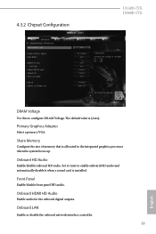
... to configure DRAM Voltage. 4.3.2 Chipset Configuration J3160B-ITX J3060B-ITX DRAM Voltage Use this to enable onboard HD audio and automatically disable it when a sound card is installed. Share Memory Configure the size of memory that is [Auto]. Onboard HDMI HD Audio Enable audio for the onboard digital outputs. Onboard LAN Enable or disable the onboard network interface controller. 33 English Primary Graphics Adapter Select a primary VGA. Front Panel Enable/disable front panel HD audio. The default value is allocated to the integrated graphics processor when the system boots...
... to configure DRAM Voltage. 4.3.2 Chipset Configuration J3160B-ITX J3060B-ITX DRAM Voltage Use this to enable onboard HD audio and automatically disable it when a sound card is installed. Share Memory Configure the size of memory that is [Auto]. Onboard HDMI HD Audio Enable audio for the onboard digital outputs. Onboard LAN Enable or disable the onboard network interface controller. 33 English Primary Graphics Adapter Select a primary VGA. Front Panel Enable/disable front panel HD audio. The default value is allocated to the integrated graphics processor when the system boots...
User Manual
Page 42
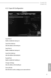
Serial Port Address Select the address of the Parallel port. Parallel Port Enable or disable the Parallel port. Serial Port 2 Enable or disable the Serial port 2. Change Settings Select the address of the Serial port. Device Mode Select the device mode according to your connected device. 37 English Serial Port Address Select the address of the Serial port. 4.3.5 Super IO Configuration J3160B-ITX J3060B-ITX Serial Port 1 Enable or disable the Serial port 1.
Serial Port Address Select the address of the Parallel port. Parallel Port Enable or disable the Parallel port. Serial Port 2 Enable or disable the Serial port 2. Change Settings Select the address of the Serial port. Device Mode Select the device mode according to your connected device. 37 English Serial Port Address Select the address of the Serial port. 4.3.5 Super IO Configuration J3160B-ITX J3060B-ITX Serial Port 1 Enable or disable the Serial port 1.
User Manual
Page 47
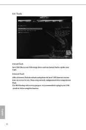
Please setup network configuration before using this function. 42 English 4.4 Tools Instant Flash Save UEFI files in your USB pen drive before using Internet Flash. *For BIOS backup and recovery purpose, it is recommended to plug in your USB storage device and run Instant Flash to update your UEFI. Internet Flash ASRock Internet Flash downloads and updates the latest UEFI firmware version from our servers for you.
Please setup network configuration before using this function. 42 English 4.4 Tools Instant Flash Save UEFI files in your USB pen drive before using Internet Flash. *For BIOS backup and recovery purpose, it is recommended to plug in your USB storage device and run Instant Flash to update your UEFI. Internet Flash ASRock Internet Flash downloads and updates the latest UEFI firmware version from our servers for you.
User Manual
Page 48
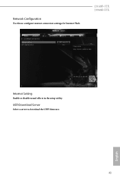
Network Configuration Use this to download the UEFI firmware. 43 English UEFI Download Server Select a server to configure internet connection settings for Internet Flash. J3160B-ITX J3060B-ITX Internet Setting Enable or disable sound effects in the setup utility.
Network Configuration Use this to download the UEFI firmware. 43 English UEFI Download Server Select a server to configure internet connection settings for Internet Flash. J3160B-ITX J3060B-ITX Internet Setting Enable or disable sound effects in the setup utility.
User Manual
Page 49
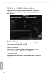
...]. Chassis Fan 1 Setting This allows you to set CPU fan 1's speed. Case Open Feature Enable or disable Case Open Feature to detect whether the chassis cover has been removed. 44 English The default value is [Full On]. CPU Fan 1 Setting This allows you to monitor the status of the hardware on your system, including the parameters of the CPU temperature, motherboard temperature, fan speed and voltage. Configuration options: [Full On] and [Automatic Mode]. Configuration options: [Full On], [Automatic Mode] and [Manual]. 4.5 Hardware...
...]. Chassis Fan 1 Setting This allows you to set CPU fan 1's speed. Case Open Feature Enable or disable Case Open Feature to detect whether the chassis cover has been removed. 44 English The default value is [Full On]. CPU Fan 1 Setting This allows you to monitor the status of the hardware on your system, including the parameters of the CPU temperature, motherboard temperature, fan speed and voltage. Configuration options: [Full On] and [Automatic Mode]. Configuration options: [Full On], [Automatic Mode] and [Manual]. 4.5 Hardware...


