User Manual
Page 2
...any errors or omissions that may not cause harmful interference, and (2) this documentation, ASRock does not provide warranty of this documentation. Disclaimer: Speciications and information contained in this motherboard contains Perchlorate, a toxic substance controlled in advance. CALIFORNIA, USA ONLY he terms... Operation is subject to change without written consent of the FCC Rules. Version 1.0 Published October 2014 Copyright©2014 ASRock INC. he Lithium battery adopted on this documentation may or may appear in the United States and other countries. "Perchlorate...
...any errors or omissions that may not cause harmful interference, and (2) this documentation, ASRock does not provide warranty of this documentation. Disclaimer: Speciications and information contained in this motherboard contains Perchlorate, a toxic substance controlled in advance. CALIFORNIA, USA ONLY he terms... Operation is subject to change without written consent of the FCC Rules. Version 1.0 Published October 2014 Copyright©2014 ASRock INC. he Lithium battery adopted on this documentation may or may appear in the United States and other countries. "Perchlorate...
User Manual
Page 3
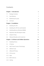
Contents Chapter 1 Introduction 1 1.1 Package Contents 1 1.2 Speciications 2 1.3 Motherboard Layout 6 1.4 I/O Panel 8 Chapter 2 Installation 9 2.1 Installing the CPU 10 2.2 Installing the CPU Fan and Heatsink 13 2.3 Installing Memory Modules (DIMM) 14 2.4 Expansion Slots...2.6 Onboard Headers and Connectors 18 Chapter 3 Software and Utilities Operation 22 3.1 Installing Drivers 22 3.2 A-Tuning 23 3.3 Intel® Smart Connect Technology 26 3.4 ASRock Cloud 30 3.5 ASRock APP Shop 40 3.5.1 UI Overview 40 3.5.2 Apps 41 3.5.3 BIOS & Drivers 44 3.5.4 Setting 45
Contents Chapter 1 Introduction 1 1.1 Package Contents 1 1.2 Speciications 2 1.3 Motherboard Layout 6 1.4 I/O Panel 8 Chapter 2 Installation 9 2.1 Installing the CPU 10 2.2 Installing the CPU Fan and Heatsink 13 2.3 Installing Memory Modules (DIMM) 14 2.4 Expansion Slots...2.6 Onboard Headers and Connectors 18 Chapter 3 Software and Utilities Operation 22 3.1 Installing Drivers 22 3.2 A-Tuning 23 3.3 Intel® Smart Connect Technology 26 3.4 ASRock Cloud 30 3.5 ASRock APP Shop 40 3.5.1 UI Overview 40 3.5.2 Apps 41 3.5.3 BIOS & Drivers 44 3.5.4 Setting 45
User Manual
Page 5
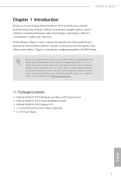
... • ASRock H91M-S1 PLUS Motherboard (Micro ATX Form Factor) • ASRock H91M-S1 PLUS Quick Installation Guide • ASRock H91M-S1 PLUS Support CD • 2 x Serial ATA (SATA) Data Cables (Optional) • 1 x I/O Panel Shield 1 English H91M-S1 PLUS Chapter 1 Introduction hank you for speciic information about the model you require technical support related to this motherboard, please visit our website for purchasing ASRock H91M-S1 PLUS motherboard, a reliable motherboard produced under ASRock's consistently...
... • ASRock H91M-S1 PLUS Motherboard (Micro ATX Form Factor) • ASRock H91M-S1 PLUS Quick Installation Guide • ASRock H91M-S1 PLUS Support CD • 2 x Serial ATA (SATA) Data Cables (Optional) • 1 x I/O Panel Shield 1 English H91M-S1 PLUS Chapter 1 Introduction hank you for speciic information about the model you require technical support related to this motherboard, please visit our website for purchasing ASRock H91M-S1 PLUS motherboard, a reliable motherboard produced under ASRock's consistently...
User Manual
Page 10
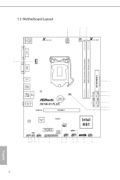
1.3 Motherboard Layout USB 2.0 T: USB0 B: USB1 PS2 Keyboard /Mouse X Fast LAN ATX12V1 PWR_FAN1 X Fast RAM DVI1 DDR3_A1 (64 bit, 240-pin module) DDR3_B1 (64 bit, 240-pin module) ATXPWR1 SATA_3 SATA_2 CPU_FAN1 VGA1 HDMI1 USB 3.0 T: USB0 B: USB1 USB 2.0 T: USB2 B: USB3 Top: RJ-45 LAN CMOS Battery H91M-S1 PLUS CLRCMOS1 1 USB 3.0 PCIE1 Audio CODEC Super I/O RoHS...
1.3 Motherboard Layout USB 2.0 T: USB0 B: USB1 PS2 Keyboard /Mouse X Fast LAN ATX12V1 PWR_FAN1 X Fast RAM DVI1 DDR3_A1 (64 bit, 240-pin module) DDR3_B1 (64 bit, 240-pin module) ATXPWR1 SATA_3 SATA_2 CPU_FAN1 VGA1 HDMI1 USB 3.0 T: USB0 B: USB1 USB 2.0 T: USB2 B: USB3 Top: RJ-45 LAN CMOS Battery H91M-S1 PLUS CLRCMOS1 1 USB 3.0 PCIE1 Audio CODEC Super I/O RoHS...
User Manual
Page 13
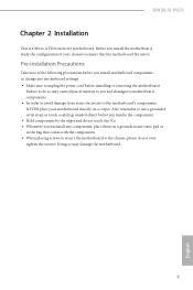
..., please do not touch the ICs. • Whenever you install the motherboard, study the coniguration of the following precautions before installing or removing the motherboard. H91M-S1 PLUS Chapter 2 Installation his is a Micro ATX form factor motherboard. Pre-installation Precautions Take note of your motherboard directly on a grounded anti-static pad or in the bag that the...
..., please do not touch the ICs. • Whenever you install the motherboard, study the coniguration of the following precautions before installing or removing the motherboard. H91M-S1 PLUS Chapter 2 Installation his is a Micro ATX form factor motherboard. Pre-installation Precautions Take note of your motherboard directly on a grounded anti-static pad or in the bag that the...
User Manual
Page 16
he cover must be placed if you wish to return the motherboard for ater service. 12 English Please save and replace the cover if the processor is removed.
he cover must be placed if you wish to return the motherboard for ater service. 12 English Please save and replace the cover if the processor is removed.
User Manual
Page 18
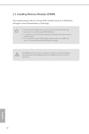
2.3 Installing Memory Modules (DIMM) his motherboard provides two 240-pin DDR3 (Double Data Rate 3) DIMM slots, and supports Dual Channel Memory Technology. 1. It is not allowed to install identical (the same ...-type) DDR3 DIMM pairs. 2. It is unable to activate Dual Channel Memory Technology with only one correct orientation. It will cause permanent damage to the motherboard and the DIMM if you always need to install a DDR or DDR2 memory module into the slot at incorrect orientation. 14 English otherwise, this...
2.3 Installing Memory Modules (DIMM) his motherboard provides two 240-pin DDR3 (Double Data Rate 3) DIMM slots, and supports Dual Channel Memory Technology. 1. It is not allowed to install identical (the same ...-type) DDR3 DIMM pairs. 2. It is unable to activate Dual Channel Memory Technology with only one correct orientation. It will cause permanent damage to the motherboard and the DIMM if you always need to install a DDR or DDR2 memory module into the slot at incorrect orientation. 14 English otherwise, this...
User Manual
Page 20
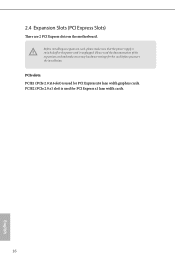
2.4 Expansion Slots (PCI Express Slots) here are 2 PCI Express slots on the motherboard. Please read the documentation of or the power cord is switched of the expansion card and make sure that the power supply is unplugged. Before installing an expansion card, please make necessary hardware settings for the card before you start the installation. PCIe slots: PCIE1 (PCIe 2.0 x16 slot) is used for PCI Express x1 lane width cards. 16 English PCIE2 (PCIe 2.0 x1 slot) is used for PCI Express x16 lane width graphics cards.
2.4 Expansion Slots (PCI Express Slots) here are 2 PCI Express slots on the motherboard. Please read the documentation of or the power cord is switched of the expansion card and make sure that the power supply is unplugged. Before installing an expansion card, please make necessary hardware settings for the card before you start the installation. PCIe slots: PCIE1 (PCIe 2.0 x16 slot) is used for PCI Express x1 lane width cards. 16 English PCIE2 (PCIe 2.0 x1 slot) is used for PCI Express x16 lane width graphics cards.
User Manual
Page 22
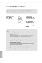
... turn of power switch, reset switch, power LED, hard drive activity LED, speaker and etc. he front panel design may conigure the way to the motherboard. System Panel Header (9-pin PANEL1) (see p.6, No. 10) PLED+ PLEDPWRBTN# GND 1 GND RESET# GND HDLEDHDLED+ Connect the power switch, reset switch and system status indicator...
... turn of power switch, reset switch, power LED, hard drive activity LED, speaker and etc. he front panel design may conigure the way to the motherboard. System Panel Header (9-pin PANEL1) (see p.6, No. 10) PLED+ PLEDPWRBTN# GND 1 GND RESET# GND HDLEDHDLED+ Connect the power switch, reset switch and system status indicator...
User Manual
Page 23
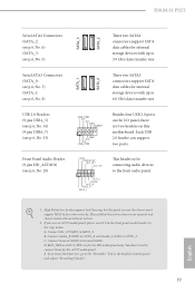
... I/O panel, there are for connecting audio devices to install your system. 2. B. High Deinition Audio supports Jack Sensing, but the panel wire on this motherboard. Connect Ground (GND) to MIC2_L. H91M-S1 PLUS Serial ATA2 Connectors (SATA_2: see p.6, No. 6) (SATA_3: see p.6, No. 5) SATA_3 SATA_2 hese two SATA2 connectors support SATA data cables for internal storage...
... I/O panel, there are for connecting audio devices to install your system. 2. B. High Deinition Audio supports Jack Sensing, but the panel wire on this motherboard. Connect Ground (GND) to MIC2_L. H91M-S1 PLUS Serial ATA2 Connectors (SATA_2: see p.6, No. 6) (SATA_3: see p.6, No. 5) SATA_3 SATA_2 hese two SATA2 connectors support SATA data cables for internal storage...
User Manual
Page 24
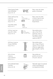
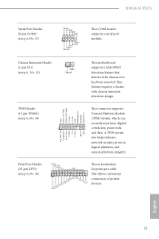
... fan connectors and match the black wire to this header. CPU Fan Connectors (4-pin CPU_FAN1) (see p.6, No. 4) 12 24 1 13 his motherboard provides a 4-Pin CPU fan (Quiet Fan) connector. Chassis Speaker Header (4-pin SPEAKER1) (see p.6, No. 12) DUMMY SPEAKER 1 +5V DUMMY...power supply, please plug it to Pin 1-3. ATX Power Connector (24-pin ATXPWR1) (see p.6, No. 21) GND +12V CPU_FAN_SPEED FAN_SPEED_CONTROL his motherboard provides a 24-pin ATX power connector. Infrared Module Header (5-pin IR1) (see p.6, No. 1) his header supports an optional wireless transmitting and ...
... fan connectors and match the black wire to this header. CPU Fan Connectors (4-pin CPU_FAN1) (see p.6, No. 4) 12 24 1 13 his motherboard provides a 4-Pin CPU fan (Quiet Fan) connector. Chassis Speaker Header (4-pin SPEAKER1) (see p.6, No. 12) DUMMY SPEAKER 1 +5V DUMMY...power supply, please plug it to Pin 1-3. ATX Power Connector (24-pin ATXPWR1) (see p.6, No. 21) GND +12V CPU_FAN_SPEED FAN_SPEED_CONTROL his motherboard provides a 24-pin ATX power connector. Infrared Module Header (5-pin IR1) (see p.6, No. 1) his header supports an optional wireless transmitting and ...
User Manual
Page 25
... STB# his is an interface for print port cable that detects if the chassis cove has been removed. his motherboard supports CASE OPEN detection feature that allows convenient connection of printer devices. H91M-S1 PLUS Serial Port Header (9-pin COM1) (see p.6, No. 18) 1 GND +3VSB LAD0_L +3V LAD3_L TPM_RST# LFRAME#_L CK_33M_TPM F_CLKRUN# SERIRQ...
... STB# his is an interface for print port cable that detects if the chassis cove has been removed. his motherboard supports CASE OPEN detection feature that allows convenient connection of printer devices. H91M-S1 PLUS Serial Port Header (9-pin COM1) (see p.6, No. 18) 1 GND +3VSB LAD0_L +3V LAD3_L TPM_RST# LFRAME#_L CK_33M_TPM F_CLKRUN# SERIRQ...
User Manual
Page 26
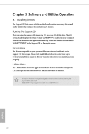
... 3 Software and Utilities Operation 3.1 Installing Drivers he Utilities Menu shows the application sotware that enhance the motherboard's features. Utilities Menu he Support CD that comes with the motherboard contains necessary drivers and useful utilities that the motherboard supports. Please click Install All or follow the installation wizard to display the menu. he drivers...
... 3 Software and Utilities Operation 3.1 Installing Drivers he Utilities Menu shows the application sotware that enhance the motherboard's features. Utilities Menu he Support CD that comes with the motherboard contains necessary drivers and useful utilities that the motherboard supports. Please click Install All or follow the installation wizard to display the menu. he drivers...
User Manual
Page 28
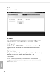
FAN-Tastic Tuning Conigure up to dampness. Dehumidiier Prevent motherboard damages due to ive diferent fan speeds using the graph. Enable this function and conigure the period of time until the computer powers on , and ...
FAN-Tastic Tuning Conigure up to dampness. Dehumidiier Prevent motherboard damages due to ive diferent fan speeds using the graph. Enable this function and conigure the period of time until the computer powers on , and ...
User Manual
Page 30
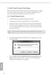
... AHCI. Enter into 0. Click on the value Start and change the value from Windows® sleep state to -date. 3.3.1 System Requirements • Conirm whether your motherboard supports this feature. • Operating system: Microsot Windows 8.1/8/7 (32- Press Win + R simultaneously in AHCI mode, please follow the instructions below. If Windows 8.1/8/7 is not in...
... AHCI. Enter into 0. Click on the value Start and change the value from Windows® sleep state to -date. 3.3.1 System Requirements • Conirm whether your motherboard supports this feature. • Operating system: Microsot Windows 8.1/8/7 (32- Press Win + R simultaneously in AHCI mode, please follow the instructions below. If Windows 8.1/8/7 is not in...
User Manual
Page 34
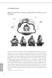
... the computer was gazillion miles away out of it remotely with another smartphone, tablet or computer. *ASRock Cloud is in a situation where you can connect with your PC seamlessly! For ASRock motherboards with a Realtek® LAN chip, ASRock Cloud allows users to remotely wake up and control their computers, or they could wake up...
... the computer was gazillion miles away out of it remotely with another smartphone, tablet or computer. *ASRock Cloud is in a situation where you can connect with your PC seamlessly! For ASRock motherboards with a Realtek® LAN chip, ASRock Cloud allows users to remotely wake up and control their computers, or they could wake up...
User Manual
Page 38
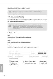
... list by the computer name you to remotely put your host computer to sleep and wake your Orbweb.ME account and password. If you use a motherboard with your host computer up from a client device. REMOTE ACCESS FROM A CLIENT DEVICE he lastest version of the LAN ports to use the Remote Wake...
... list by the computer name you to remotely put your host computer to sleep and wake your Orbweb.ME account and password. If you use a motherboard with your host computer up from a client device. REMOTE ACCESS FROM A CLIENT DEVICE he lastest version of the LAN ports to use the Remote Wake...
User Manual
Page 44
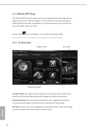
Click on your motherboard up to download apps from the ASRock APP Shop. 3.5.1 UI Overview Category Panel Hot News Information Panel Category Panel: he information panel in the center displays data about the currently selected category ... know more. 40 English You can install various apps and support utilities quickly and easily, and optimize your system and keep your desktop to access ASRock APP Shop utility. *You need to be connected to the Internet to date simply with a few clicks. Hot News: he...
Click on your motherboard up to download apps from the ASRock APP Shop. 3.5.1 UI Overview Category Panel Hot News Information Panel Category Panel: he information panel in the center displays data about the currently selected category ... know more. 40 English You can install various apps and support utilities quickly and easily, and optimize your system and keep your desktop to access ASRock APP Shop utility. *You need to be connected to the Internet to date simply with a few clicks. Hot News: he...
User Manual
Page 56
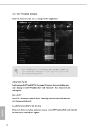
Advanced Turbo Load optimized CPU and GPU OC settings. Load Optimized GPU OC Setting Please note that overclocking may cause damage to your CPU and motherboard. Non-Z OC Non-Z OC allows users with a K-Series Haswell processor to your own risk and expense. 52 English It should be done at your ...CPU and motherboard. 4.3 OC Tweaker Screen In the OC Tweaker screen, you see on your screen. It should be done at your own risk and expense. Please ...
Advanced Turbo Load optimized CPU and GPU OC settings. Load Optimized GPU OC Setting Please note that overclocking may cause damage to your CPU and motherboard. Non-Z OC Non-Z OC allows users with a K-Series Haswell processor to your own risk and expense. 52 English It should be done at your ...CPU and motherboard. 4.3 OC Tweaker Screen In the OC Tweaker screen, you see on your screen. It should be done at your own risk and expense. Please ...
User Manual
Page 57
... Overvoltage Enable for better overclocking capabilities. H91M-S1 PLUS CPU Coniguration Multi core enhancement Improve the system's performance by the CPU Ratio multiplied with the BCLK. Disable to your own risk and expense. Please note that overclocking may improve performance. 53 English Increasing the CPU Ratio will be done at your CPU and motherboard.
... Overvoltage Enable for better overclocking capabilities. H91M-S1 PLUS CPU Coniguration Multi core enhancement Improve the system's performance by the CPU Ratio multiplied with the BCLK. Disable to your own risk and expense. Please note that overclocking may improve performance. 53 English Increasing the CPU Ratio will be done at your CPU and motherboard.

