User Manual
Page 3
... Contents 1 1.2 Speciications 2 1.3 Motherboard Layout 6 1.4 I/O Panel 8 Chapter 2 Installation 9 2.1 Installing the CPU 10 2.2 Installing the CPU Fan and Heatsink 13 2.3 Installing Memory Modules (DIMM) 14 2.4 Expansion Slots (PCI Express Slots) 16 2.5 Jumpers Setup 17 2.6 Onboard Headers and Connectors 18 Chapter 3 Software and Utilities Operation 22 3.1 Installing Drivers 22 3.2 A-Tuning 23 3.3 Intel® Smart Connect Technology 26 3.4 ASRock Cloud 30 3.5 ASRock APP Shop 40 3.5.1 UI Overview 40 3.5.2 Apps 41 3.5.3 BIOS & Drivers 44 3.5.4 Setting 45
... Contents 1 1.2 Speciications 2 1.3 Motherboard Layout 6 1.4 I/O Panel 8 Chapter 2 Installation 9 2.1 Installing the CPU 10 2.2 Installing the CPU Fan and Heatsink 13 2.3 Installing Memory Modules (DIMM) 14 2.4 Expansion Slots (PCI Express Slots) 16 2.5 Jumpers Setup 17 2.6 Onboard Headers and Connectors 18 Chapter 3 Software and Utilities Operation 22 3.1 Installing Drivers 22 3.2 A-Tuning 23 3.3 Intel® Smart Connect Technology 26 3.4 ASRock Cloud 30 3.5 ASRock APP Shop 40 3.5.1 UI Overview 40 3.5.2 Apps 41 3.5.3 BIOS & Drivers 44 3.5.4 Setting 45
User Manual
Page 5
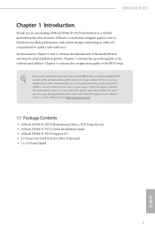
... endurance. ASRock website http://www.asrock.com. 1.1 Package Contents • ASRock H91M-S1 PLUS Motherboard (Micro ATX Form Factor) • ASRock H91M-S1 PLUS Quick Installation Guide • ASRock H91M-S1 PLUS Support CD • 2 x Serial ATA (SATA) Data Cables (Optional) • 1 x I/O Panel Shield 1 English If you are using. H91M-S1 PLUS Chapter 1 Introduction hank you for speciic information about the model you require technical support related to this manual, Chapter 1 and 2 contains the introduction of the motherboard and step-by-step installation guides.
... endurance. ASRock website http://www.asrock.com. 1.1 Package Contents • ASRock H91M-S1 PLUS Motherboard (Micro ATX Form Factor) • ASRock H91M-S1 PLUS Quick Installation Guide • ASRock H91M-S1 PLUS Support CD • 2 x Serial ATA (SATA) Data Cables (Optional) • 1 x I/O Panel Shield 1 English If you are using. H91M-S1 PLUS Chapter 1 Introduction hank you for speciic information about the model you require technical support related to this manual, Chapter 1 and 2 contains the introduction of the motherboard and step-by-step installation guides.
User Manual
Page 7
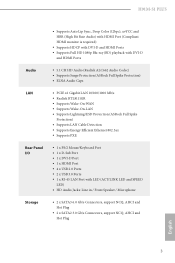
H91M-S1 PLUS Audio LAN Rear Panel I/O Storage • Supports Auto Lip Sync, Deep Color (12bpc), xvYCC and HBR (High Bit Rate Audio) with HDMI Port (Compliant HDMI monitor is required) • Supports HDCP with DVI-D and HDMI Ports • Supports Full HD 1080p Blu-ray (BD) playback with DVI-D and HDMI Ports • 5.1 CH HD Audio (Realtek ALC662 Audio Codec) • Supports Surge Protection (ASRock Full Spike Protection) • ELNA Audio Caps • PCIE x1 Gigabit LAN 10/100...
H91M-S1 PLUS Audio LAN Rear Panel I/O Storage • Supports Auto Lip Sync, Deep Color (12bpc), xvYCC and HBR (High Bit Rate Audio) with HDMI Port (Compliant HDMI monitor is required) • Supports HDCP with DVI-D and HDMI Ports • Supports Full HD 1080p Blu-ray (BD) playback with DVI-D and HDMI Ports • 5.1 CH HD Audio (Realtek ALC662 Audio Codec) • Supports Surge Protection (ASRock Full Spike Protection) • ELNA Audio Caps • PCIE x1 Gigabit LAN 10/100...

User Manual
Page 8
...IR Header • 1 x Print Port Header • 1 x COM Port Header • 1 x Chassis Intrusion Header • 1 x TPM Header • 1 x CPU Fan Connector (4-pin) • 1 x Chassis Fan Connector (4-pin) • 1 x Power Fan Connector (3-pin) • 1 x 24 pin ATX Power Connector • 1 x 4 pin 12V Power Connector • 1 x Front Panel Audio Connector • 2 x USB 2.0 Headers (Support 4 USB 2.0 ports) • 32Mb AMI UEFI Legal BIOS with Multilingual GUI support • ACPI 1.1 Compliance Wake Up Events • SMBIOS 2.3.1 Support • CPU, DRAM, PCH 1.05V, PCH 1.5V Voltage...
...IR Header • 1 x Print Port Header • 1 x COM Port Header • 1 x Chassis Intrusion Header • 1 x TPM Header • 1 x CPU Fan Connector (4-pin) • 1 x Chassis Fan Connector (4-pin) • 1 x Power Fan Connector (3-pin) • 1 x 24 pin ATX Power Connector • 1 x 4 pin 12V Power Connector • 1 x Front Panel Audio Connector • 2 x USB 2.0 Headers (Support 4 USB 2.0 ports) • 32Mb AMI UEFI Legal BIOS with Multilingual GUI support • ACPI 1.1 Compliance Wake Up Events • SMBIOS 2.3.1 Support • CPU, DRAM, PCH 1.05V, PCH 1.5V Voltage...
User Manual
Page 10
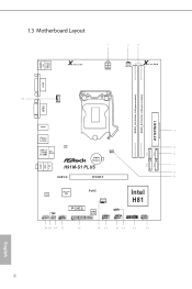
1.3 Motherboard Layout USB 2.0 T: USB0 B: USB1 PS2 Keyboard /Mouse X Fast LAN ATX12V1 PWR_FAN1 X Fast RAM DVI1 DDR3_A1 (64 bit, 240-pin module) DDR3_B1 (64 bit, 240-pin module) ATXPWR1 SATA_3 SATA_2 CPU_FAN1 VGA1 HDMI1 USB 3.0 T: USB0 B: USB1 USB 2.0 T: USB2 B: USB3 Top: RJ-45 LAN CMOS Battery H91M-S1 PLUS CLRCMOS1 1 USB 3.0 PCIE1 Audio CODEC Super I/O RoHS CHA_FAN1 Intel H81 HD_AUDIO1 CI1 1 IR1 1 1 COM1 1 PCIE2 LPT1 32Mb BIOS 1 SPEAKER1 1 USB4_5 1 USB6_7 1 1 TPMS1 PLED PWRBTN...
1.3 Motherboard Layout USB 2.0 T: USB0 B: USB1 PS2 Keyboard /Mouse X Fast LAN ATX12V1 PWR_FAN1 X Fast RAM DVI1 DDR3_A1 (64 bit, 240-pin module) DDR3_B1 (64 bit, 240-pin module) ATXPWR1 SATA_3 SATA_2 CPU_FAN1 VGA1 HDMI1 USB 3.0 T: USB0 B: USB1 USB 2.0 T: USB2 B: USB3 Top: RJ-45 LAN CMOS Battery H91M-S1 PLUS CLRCMOS1 1 USB 3.0 PCIE1 Audio CODEC Super I/O RoHS CHA_FAN1 Intel H81 HD_AUDIO1 CI1 1 IR1 1 1 COM1 1 PCIE2 LPT1 32Mb BIOS 1 SPEAKER1 1 USB4_5 1 USB6_7 1 1 TPMS1 PLED PWRBTN...
User Manual
Page 11
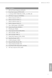
...240-pin DDR3 DIMM Slots (DDR3_A1, DDR3_B1) 4 ATX Power Connector (ATXPWR1) 5 SATA2 Connector (SATA_3) 6 SATA2 Connector (SATA_2) 7 SATA3 Connector (SATA_0) 8 SATA3 Connector (SATA_1) 9 Clear CMOS Jumper (CLRCMOS1) 10 System Panel Header (PANEL1) 11 TPM Header (TPMS1) 12 Chassis Speaker Header (SPEAKER1) 13 USB 2.0 Header (USB6_7) 14 USB 2.0 Header (USB4_5) 15 Chassis Fan Connector (CHA_FAN1) 16 Print Port Header (LPT1) 17 COM Port Header (COM1) 18 Infrared Module Header (IR1) 19 Chassis Intrusion Header (CI1) 20 Front Panel Audio Header (HD_AUDIO1) 21 CPU Fan Connector (CPU_FAN1) H91M-S1 PLUS...
...240-pin DDR3 DIMM Slots (DDR3_A1, DDR3_B1) 4 ATX Power Connector (ATXPWR1) 5 SATA2 Connector (SATA_3) 6 SATA2 Connector (SATA_2) 7 SATA3 Connector (SATA_0) 8 SATA3 Connector (SATA_1) 9 Clear CMOS Jumper (CLRCMOS1) 10 System Panel Header (PANEL1) 11 TPM Header (TPMS1) 12 Chassis Speaker Header (SPEAKER1) 13 USB 2.0 Header (USB6_7) 14 USB 2.0 Header (USB4_5) 15 Chassis Fan Connector (CHA_FAN1) 16 Print Port Header (LPT1) 17 COM Port Header (COM1) 18 Infrared Module Header (IR1) 19 Chassis Intrusion Header (CI1) 20 Front Panel Audio Header (HD_AUDIO1) 21 CPU Fan Connector (CPU_FAN1) H91M-S1 PLUS...
User Manual
Page 13
... to use a grounded wrist strap or touch a safety grounded object before installing or removing the motherboard. Doing so may cause physical injuries to you install motherboard components or change any components, place them on a carpet. H91M-S1 PLUS Chapter 2 Installation his is a Micro ATX form factor motherboard. Before you uninstall any motherboard settings. • Make sure to the motherboard's components, NEVER place your chassis to the chassis, please...
... to use a grounded wrist strap or touch a safety grounded object before installing or removing the motherboard. Doing so may cause physical injuries to you install motherboard components or change any components, place them on a carpet. H91M-S1 PLUS Chapter 2 Installation his is a Micro ATX form factor motherboard. Before you uninstall any motherboard settings. • Make sure to the motherboard's components, NEVER place your chassis to the chassis, please...
User Manual
Page 20
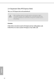
Before installing an expansion card, please make necessary hardware settings for the card before you start the installation. PCIE2 (PCIe 2.0 x1 slot) is used for PCI Express x1 lane width cards. 16 English 2.4 Expansion Slots (PCI Express Slots) here are 2 PCI Express slots on the motherboard. PCIe slots: PCIE1 (PCIe 2.0 x16 slot) is unplugged. Please read the documentation of the expansion card and make sure that the power supply is switched of or the power cord is used for PCI Express x16 lane width graphics cards.
Before installing an expansion card, please make necessary hardware settings for the card before you start the installation. PCIE2 (PCIe 2.0 x1 slot) is used for PCI Express x1 lane width cards. 16 English 2.4 Expansion Slots (PCI Express Slots) here are 2 PCI Express slots on the motherboard. PCIe slots: PCIE1 (PCIe 2.0 x16 slot) is unplugged. Please read the documentation of the expansion card and make sure that the power supply is switched of or the power cord is used for PCI Express x16 lane width graphics cards.
User Manual
Page 21
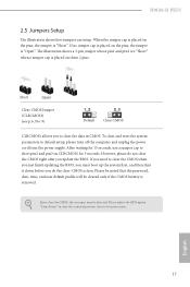
... the power supply. Please adjust the BIOS option "Clear Status" to default setup, please turn of previous chassis intrusion status. If you need to clear the CMOS when you just inish updating the BIOS, you must boot up the system irst, and then shut it down before you to short pin2 and pin3 on the pins, the jumper is removed. However, please do the clear-CMOS action. H91M-S1 PLUS 2.5 Jumpers Setup he illustration shows a 3-pin jumper...
... the power supply. Please adjust the BIOS option "Clear Status" to default setup, please turn of previous chassis intrusion status. If you need to clear the CMOS when you just inish updating the BIOS, you must boot up the system irst, and then shut it down before you to short pin2 and pin3 on the pins, the jumper is removed. However, please do the clear-CMOS action. H91M-S1 PLUS 2.5 Jumpers Setup he illustration shows a 3-pin jumper...
User Manual
Page 22
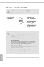
... Panel Header (9-pin PANEL1) (see p.6, No. 10) PLED+ PLEDPWRBTN# GND 1 GND RESET# GND HDLEDHDLED+ Connect the power switch, reset switch and system status indicator on when the hard drive is in S4 sleep state or powered of power switch, reset switch, power LED, hard drive activity LED, speaker and etc. he LED is in S3 sleep state. When connecting your system using the power switch. he LED is of when the system is on the chassis to perform a normal restart. 2.6 Onboard Headers and Connectors Onboard headers...
... Panel Header (9-pin PANEL1) (see p.6, No. 10) PLED+ PLEDPWRBTN# GND 1 GND RESET# GND HDLEDHDLED+ Connect the power switch, reset switch and system status indicator on when the hard drive is in S4 sleep state or powered of power switch, reset switch, power LED, hard drive activity LED, speaker and etc. he LED is in S3 sleep state. When connecting your system using the power switch. he LED is of when the system is on the chassis to perform a normal restart. 2.6 Onboard Headers and Connectors Onboard headers...
User Manual
Page 23
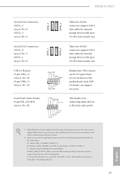
...). Front Panel Audio Header (9-pin HD_AUDIO1) (see p.6, No. 8) SATA_1 SATA_0 hese two SATA3 connectors support SATA data cables for internal storage devices with up to install your system. 2. High Deinition Audio supports Jack Sensing, but the panel wire on this motherboard. D. H91M-S1 PLUS Serial ATA2 Connectors (SATA_2: see p.6, No. 6) (SATA_3: see p.6, No. 13) USB_PWR P-7 P+7 GND DUMMY 1 GND P+6 P-6 USB_PWR Besides four USB 2.0 ports on the I/O panel, there are for the HD audio panel only. Please follow the instructions in...
...). Front Panel Audio Header (9-pin HD_AUDIO1) (see p.6, No. 8) SATA_1 SATA_0 hese two SATA3 connectors support SATA data cables for internal storage devices with up to install your system. 2. High Deinition Audio supports Jack Sensing, but the panel wire on this motherboard. D. H91M-S1 PLUS Serial ATA2 Connectors (SATA_2: see p.6, No. 6) (SATA_3: see p.6, No. 13) USB_PWR P-7 P+7 GND DUMMY 1 GND P+6 P-6 USB_PWR Besides four USB 2.0 ports on the I/O panel, there are for the HD audio panel only. Please follow the instructions in...
User Manual
Page 25
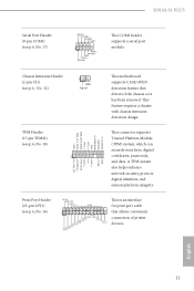
... SMB_CLK_MAIN GND his motherboard supports CASE OPEN detection feature that allows convenient connection of printer devices. Chassis Intrusion Header (2-pin CI1) (see p.6, No. 16) AFD# ERROR# PINIT# SLIN# GND 1 SPD7 SPD6 ACK# SPD5 BUSY SPD4 PE SPD3 SLCT SPD2 SPD1 SPD0 STB# his is an interface for print port cable that detects if the chassis cove has been removed. Print Port Header (25-pin LPT1) (see...
... SMB_CLK_MAIN GND his motherboard supports CASE OPEN detection feature that allows convenient connection of printer devices. Chassis Intrusion Header (2-pin CI1) (see p.6, No. 16) AFD# ERROR# PINIT# SLIN# GND 1 SPD7 SPD6 ACK# SPD5 BUSY SPD4 PE SPD3 SLCT SPD2 SPD1 SPD0 STB# his is an interface for print port cable that detects if the chassis cove has been removed. Print Port Header (25-pin LPT1) (see...
User Manual
Page 26
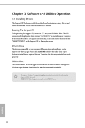
... necessary drivers and useful utilities that the motherboard supports. he drivers compatible to install those required drivers. To improve Windows 7 compatibility, please download and install the following hot ix provided by Microsot. Click on a speciic item then follow the order from top to bottom to your system will be auto-detected and listed on the ile "ASRSETUP.EXE" in your CD-ROM drive. herefore, the drivers you install can work...
... necessary drivers and useful utilities that the motherboard supports. he drivers compatible to install those required drivers. To improve Windows 7 compatibility, please download and install the following hot ix provided by Microsot. Click on a speciic item then follow the order from top to bottom to your system will be auto-detected and listed on the ile "ASRSETUP.EXE" in your CD-ROM drive. herefore, the drivers you install can work...
User Manual
Page 27
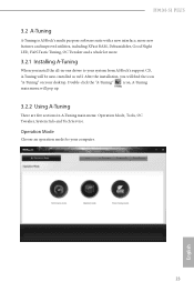
H91M-S1 PLUS 3.2 A-Tuning A-Tuning is ASRock's multi purpose sotware suite with a new interface, more new features and improved utilities, including XFast RAM, Dehumidiier, Good Night LED, FAN-Tastic Tuning, OC Tweaker and a whole lot more. 3.2.1 Installing A-Tuning When you will ind the icon "A-Tuning" on your desktop. Operation Mode Choose an operation mode for your system from ASRock's support CD, A-Tuning will pop up...
H91M-S1 PLUS 3.2 A-Tuning A-Tuning is ASRock's multi purpose sotware suite with a new interface, more new features and improved utilities, including XFast RAM, Dehumidiier, Good Night LED, FAN-Tastic Tuning, OC Tweaker and a whole lot more. 3.2.1 Installing A-Tuning When you will ind the icon "A-Tuning" on your desktop. Operation Mode Choose an operation mode for your system from ASRock's support CD, A-Tuning will pop up...
User Manual
Page 30
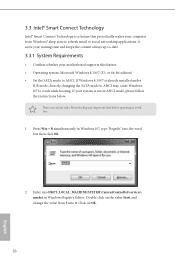
or 64-bit edition) • Set the SATA mode to crash while booting. here are certain risks. Press Win + R simultaneously in Windows Registry Editor. Enter into HKEY_LOCAL_MACHINE\SYSTEM\CurrentControlSet\services\ msahci in Windows 8/7, type "Regedit" into 0. If Windows 8.1/8/7 is already installed under IDE mode, directly changing the SATA mode to AHCI may cause Windows 8/7 to AHCI. Click on the value Start and change the value from Windows® sleep state to refresh email or social networking applications...
or 64-bit edition) • Set the SATA mode to crash while booting. here are certain risks. Press Win + R simultaneously in Windows Registry Editor. Enter into HKEY_LOCAL_MACHINE\SYSTEM\CurrentControlSet\services\ msahci in Windows 8/7, type "Regedit" into 0. If Windows 8.1/8/7 is already installed under IDE mode, directly changing the SATA mode to AHCI may cause Windows 8/7 to AHCI. Click on the value Start and change the value from Windows® sleep state to refresh email or social networking applications...
User Manual
Page 35
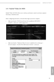
he actual screen may difer by model. • Make sure that the "PCIE Devices Power On" is enabled in UEFI SETUP UTILITY > Advanced > ACPI Coniguration. *he UEFI screen is enabled in Device Manager > Network Adapters > Realtek PCIe GBE Family Controller > Advanced. 31 English H91M-S1 PLUS 3.4.1 Realtek® Wake-On-WAN Realtek® Wake-On-WAN allows you to wake up and remote control your host computer: • Make sure that the "Shutdown Wake-On-Lan" is for reference only. Before coniguring this feature, verify the followings on your home computer from sleep or shutdown state.
he actual screen may difer by model. • Make sure that the "PCIE Devices Power On" is enabled in UEFI SETUP UTILITY > Advanced > ACPI Coniguration. *he UEFI screen is enabled in Device Manager > Network Adapters > Realtek PCIe GBE Family Controller > Advanced. 31 English H91M-S1 PLUS 3.4.1 Realtek® Wake-On-WAN Realtek® Wake-On-WAN allows you to wake up and remote control your host computer: • Make sure that the "Shutdown Wake-On-Lan" is for reference only. Before coniguring this feature, verify the followings on your home computer from sleep or shutdown state.
User Manual
Page 53
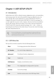
... section explains how to use the UEFI SETUP UTILITY to enter the UEFI SETUP UTILITY ater POST, restart the system by pressing + + , or by pressing or right ater you power on the computer, otherwise, the Power-On-Self-Test (POST) will it make BIOS setup less diicult but also a lot more amusing. H91M-S1 PLUS Chapter 4 UEFI SETUP UTILITY 4.1 Introduction ASRock Interactive UEFI is constantly being updated, the following UEFI setup screens and descriptions are for...
... section explains how to use the UEFI SETUP UTILITY to enter the UEFI SETUP UTILITY ater POST, restart the system by pressing + + , or by pressing or right ater you power on the computer, otherwise, the Power-On-Self-Test (POST) will it make BIOS setup less diicult but also a lot more amusing. H91M-S1 PLUS Chapter 4 UEFI SETUP UTILITY 4.1 Introduction ASRock Interactive UEFI is constantly being updated, the following UEFI setup screens and descriptions are for...
User Manual
Page 68
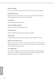
Front Panel Enable/disable front panel HD audio. Render Standby Power down . Onboard LAN Enable or disable the onboard network interface controller. Restore on . Good Night LED By enabling Good Night LED, the Power/LAN LEDs will start to enable onboard HD audio and automatically disable it when a sound card is shut down the render unit when the GPU is idle for the onboard digital outputs. Onboard HD Audio Enable/disable onboard HD audio. Set to Auto to boot up when the power recovers. Onboard HDMI HD Audio Enable audio for lower power consumption...
Front Panel Enable/disable front panel HD audio. Render Standby Power down . Onboard LAN Enable or disable the onboard network interface controller. Restore on . Good Night LED By enabling Good Night LED, the Power/LAN LEDs will start to enable onboard HD audio and automatically disable it when a sound card is shut down the render unit when the GPU is idle for the onboard digital outputs. Onboard HD Audio Enable/disable onboard HD audio. Set to Auto to boot up when the power recovers. Onboard HDMI HD Audio Enable audio for lower power consumption...
User Manual
Page 74
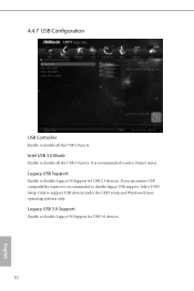
Legacy USB Support Enable or disable Legacy OS Support for USB 3.0 devices. 70 English If you encounter USB compatibility issues it is recommended to disable legacy USB support. It is recommended to select [Smart Auto]. Select UEFI Setup Only to support USB devices under the UEFI setup and Windows/Linux operating systems only. 4.4.7 USB Coniguration USB Controller Enable or disable all the USB 3.0 ports. Legacy USB 3.0 Support Enable or disable Legacy OS Support for USB 2.0 devices. Intel USB 3.0 Mode Enable or disable all the USB 2.0 ports.
Legacy USB Support Enable or disable Legacy OS Support for USB 3.0 devices. 70 English If you encounter USB compatibility issues it is recommended to disable legacy USB support. It is recommended to select [Smart Auto]. Select UEFI Setup Only to support USB devices under the UEFI setup and Windows/Linux operating systems only. 4.4.7 USB Coniguration USB Controller Enable or disable all the USB 3.0 ports. Legacy USB 3.0 Support Enable or disable Legacy OS Support for USB 2.0 devices. Intel USB 3.0 Mode Enable or disable all the USB 2.0 ports.

User Manual
Page 76
... for Internet Flash. 72 English Instant Flash Save UEFI iles in your system via an USB storage device, then downloads and installs the other required drivers automatically. Please setup network coniguration before using UEFI Tech Service. Internet Flash ASRock Internet Flash downloads and updates the latest UEFI irmware version from our support CD, Easy Driver Installer is recommended to update your PC. Easy Driver Installer For users that installs the LAN driver to conigure internet connection settings for you are having trouble with your...
... for Internet Flash. 72 English Instant Flash Save UEFI iles in your system via an USB storage device, then downloads and installs the other required drivers automatically. Please setup network coniguration before using UEFI Tech Service. Internet Flash ASRock Internet Flash downloads and updates the latest UEFI irmware version from our support CD, Easy Driver Installer is recommended to update your PC. Easy Driver Installer For users that installs the LAN driver to conigure internet connection settings for you are having trouble with your...


