

User Manual
Page 3
...Package Contents 1 1.2 Speciications 2 1.3 Motherboard Layout 5 1.4 I/O Panel 7 Chapter 2 Installation 8 2.1 Installing the CPU 9 2.2 Installing the CPU Fan and Heatsink 12 2.3 Installing Memory Modules (DIMM) 13 2.4 Expansion Slots (PCI Express Slots) 15 2.5 Jumpers Setup 16 2.6 Onboard Headers and Connectors 17 Chapter 3 Software and Utilities Operation 21 3.1 Installing Drivers 21 3.2 A-Tuning 22 3.3 Intel® Smart Connect Technology 28 3.4 ASRock APP Shop 33 3.4.1 UI Overview 33 3.4.2 Apps 34 3.4.3 BIOS & Drivers 37 3.4.4 Setting 38 3.5 Start8 39
...Package Contents 1 1.2 Speciications 2 1.3 Motherboard Layout 5 1.4 I/O Panel 7 Chapter 2 Installation 8 2.1 Installing the CPU 9 2.2 Installing the CPU Fan and Heatsink 12 2.3 Installing Memory Modules (DIMM) 13 2.4 Expansion Slots (PCI Express Slots) 15 2.5 Jumpers Setup 16 2.6 Onboard Headers and Connectors 17 Chapter 3 Software and Utilities Operation 21 3.1 Installing Drivers 21 3.2 A-Tuning 22 3.3 Intel® Smart Connect Technology 28 3.4 ASRock APP Shop 33 3.4.1 UI Overview 33 3.4.2 Apps 34 3.4.3 BIOS & Drivers 37 3.4.4 Setting 38 3.5 Start8 39
User Manual
Page 5
... the latest VGA cards and CPU support list on ASRock's website without notice. Chapter 3 contains the operation guide of the BIOS setup. In case any modiications of the motherboard and step-by-step installation guides. ASRock website http://www.asrock.com. 1.1 Package Contents • ASRock H81M-DG4 Motherboard (Micro ATX Form Factor) • ASRock H81M-DG4 Quick Installation Guide • ASRock H81M-DG4 Support CD • 2 x Serial ATA (SATA) Data Cables (Optional) • 1 x I/O Panel Shield 1 English If you require technical support related to change without further...
... the latest VGA cards and CPU support list on ASRock's website without notice. Chapter 3 contains the operation guide of the BIOS setup. In case any modiications of the motherboard and step-by-step installation guides. ASRock website http://www.asrock.com. 1.1 Package Contents • ASRock H81M-DG4 Motherboard (Micro ATX Form Factor) • ASRock H81M-DG4 Quick Installation Guide • ASRock H81M-DG4 Support CD • 2 x Serial ATA (SATA) Data Cables (Optional) • 1 x I/O Panel Shield 1 English If you require technical support related to change without further...
User Manual
Page 7
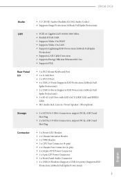
...; 2 x USB 3.0 Ports (Supports ESD Protection (ASRock Full Spike Protection)) • 1 x RJ-45 LAN Port with LED (ACT/LINK LED and SPEED LED) • HD Audio Jack: Line in / Front Speaker / Microphone Storage • 2 x SATA3 6.0 Gb/s Connectors, support NCQ, AHCI and Hot Plug • 2 x SATA2 3.0 Gb/s Connectors, support NCQ, AHCI and Hot Plug Connector • 1 x Power LED Header • 1 x Chassis Intrusion Header • 1 x TPM Header • 1 x CPU Fan Connector (4-pin) • 1 x Chassis Fan Connector (4-pin) • 1 x 24 pin ATX Power Connector • 1 x 4 pin 12V Power...
...; 2 x USB 3.0 Ports (Supports ESD Protection (ASRock Full Spike Protection)) • 1 x RJ-45 LAN Port with LED (ACT/LINK LED and SPEED LED) • HD Audio Jack: Line in / Front Speaker / Microphone Storage • 2 x SATA3 6.0 Gb/s Connectors, support NCQ, AHCI and Hot Plug • 2 x SATA2 3.0 Gb/s Connectors, support NCQ, AHCI and Hot Plug Connector • 1 x Power LED Header • 1 x Chassis Intrusion Header • 1 x TPM Header • 1 x CPU Fan Connector (4-pin) • 1 x Chassis Fan Connector (4-pin) • 1 x 24 pin ATX Power Connector • 1 x 4 pin 12V Power...

User Manual
Page 8
....asrock.com Please realize that Windows® cannot use. BIOS Feature Hardware Monitor OS Certiications • 32Mb AMI UEFI Legal BIOS with overclocking, including adjusting the setting in the BIOS, applying Untied Overclocking Technology, or using thirdparty overclocking tools. English 4 Overclocking may be done at your system. perature) • CPU/Chassis Fan multi-speed control • CASE OPEN detection • Voltage monitoring: +12V, +5V, +3.3V, CPU Vcore • Microsot® Windows® 8.1 32-bit / 8.1 64-bit / 8 32-bit...
....asrock.com Please realize that Windows® cannot use. BIOS Feature Hardware Monitor OS Certiications • 32Mb AMI UEFI Legal BIOS with overclocking, including adjusting the setting in the BIOS, applying Untied Overclocking Technology, or using thirdparty overclocking tools. English 4 Overclocking may be done at your system. perature) • CPU/Chassis Fan multi-speed control • CASE OPEN detection • Voltage monitoring: +12V, +5V, +3.3V, CPU Vcore • Microsot® Windows® 8.1 32-bit / 8.1 64-bit / 8 32-bit...

User Manual
Page 10
No. Description 1 CPU Fan Connector (CPU_FAN1) 2 2 x 240-pin DDR3 DIMM Slots (DDR3_A1, DDR3_B1) 3 ATX Power Connector (ATXPWR1) 4 System Panel Header (PANEL1) 5 SATA2 Connector (SATA_2) 6 SATA2 Connector (SATA_3) 7 Power LED Header (PLED1) 8 TPM Header (TPMS1) 9 USB 2.0 Header (USB4_5) 10 USB 2.0 Header (USB6_7) 11 SATA3 Connector (SATA_1) 12 SATA3 Connector (SATA_0) 13 Chassis Fan Connector (CHA_FAN1) 14 Chassis Speaker Header (SPEAKER1) 15 Chassis Intrusion Header (CI1) 16 Clear CMOS Jumper (CLRCMOS1) 17 Front Panel Audio Header (HD_AUDIO1) 18 ATX 12V Power Connector (ATX12V1) 6 English
No. Description 1 CPU Fan Connector (CPU_FAN1) 2 2 x 240-pin DDR3 DIMM Slots (DDR3_A1, DDR3_B1) 3 ATX Power Connector (ATXPWR1) 4 System Panel Header (PANEL1) 5 SATA2 Connector (SATA_2) 6 SATA2 Connector (SATA_3) 7 Power LED Header (PLED1) 8 TPM Header (TPMS1) 9 USB 2.0 Header (USB4_5) 10 USB 2.0 Header (USB6_7) 11 SATA3 Connector (SATA_1) 12 SATA3 Connector (SATA_0) 13 Chassis Fan Connector (CHA_FAN1) 14 Chassis Speaker Header (SPEAKER1) 15 Chassis Intrusion Header (CI1) 16 Clear CMOS Jumper (CLRCMOS1) 17 Front Panel Audio Header (HD_AUDIO1) 18 ATX 12V Power Connector (ATX12V1) 6 English

User Manual
Page 19
PCIE2 (PCIe 2.0 x16 slot) is used for PCI Express x16 lane width graphics cards. 15 English PCIe slots: PCIE1 (PCIe 2.0 x1 slot) is used for the card before you start the installation. Before installing an expansion card, please make necessary hardware settings for PCI Express x1 lane width cards. H81M-DG4 2.4 Expansion Slots (PCI Express Slots) here are 2 PCI Express slots on the motherboard. Please read the documentation of the expansion card and make sure that the power supply is switched of or the power cord is unplugged.
PCIE2 (PCIe 2.0 x16 slot) is used for PCI Express x16 lane width graphics cards. 15 English PCIe slots: PCIE1 (PCIe 2.0 x1 slot) is used for the card before you start the installation. Before installing an expansion card, please make necessary hardware settings for PCI Express x1 lane width cards. H81M-DG4 2.4 Expansion Slots (PCI Express Slots) here are 2 PCI Express slots on the motherboard. Please read the documentation of the expansion card and make sure that the power supply is switched of or the power cord is unplugged.

User Manual
Page 20
... the power supply. However, please do the clear-CMOS action. Please adjust the BIOS option "Clear Status" to default setup, please turn of previous chassis intrusion status. If no jumper cap is placed on the pins, the jumper is "Open". When the jumper cap is placed on the pins, the jumper is "Short". If you update the BIOS. Ater waiting for 15 seconds, use a jumper cap to short pin2 and pin3 on these 2 pins. 2.5 Jumpers Setup...
... the power supply. However, please do the clear-CMOS action. Please adjust the BIOS option "Clear Status" to default setup, please turn of previous chassis intrusion status. If no jumper cap is placed on the pins, the jumper is "Open". When the jumper cap is placed on the pins, the jumper is "Short". If you update the BIOS. Ater waiting for 15 seconds, use a jumper cap to short pin2 and pin3 on these 2 pins. 2.5 Jumpers Setup...

User Manual
Page 21
... below. When connecting your system using the power switch. English 17 H81M-DG4 2.6 Onboard Headers and Connectors Onboard headers and connectors are matched correctly. PLED (System Power LED): Connect to the power status indicator on the chassis to the hard drive activity LED on the chassis front panel. Note the positive and negative pins before connecting the cables. Press the reset switch to restart the computer if the computer freezes and fails to the motherboard. he LED keeps blinking...
... below. When connecting your system using the power switch. English 17 H81M-DG4 2.6 Onboard Headers and Connectors Onboard headers and connectors are matched correctly. PLED (System Power LED): Connect to the power status indicator on the chassis to the hard drive activity LED on the chassis front panel. Note the positive and negative pins before connecting the cables. Press the reset switch to restart the computer if the computer freezes and fails to the motherboard. he LED keeps blinking...

User Manual
Page 22
... GND PRESENCE# MIC_RET OUT_RET his header is for connecting audio devices to the "FrontMic" Tab in our manual and chassis manual to Ground (GND). Each USB 2.0 header can support two ports. D. To activate the front mic, go to the front audio panel. 1. Serial ATA3 Connectors (SATA_0: see p.5, No. 12) (SATA_1: see p.5, No. 11) SATA_0 SATA_1 hese two SATA3 connectors support SATA data cables for internal storage devices with up to 6.0 Gb/s data...
... GND PRESENCE# MIC_RET OUT_RET his header is for connecting audio devices to the "FrontMic" Tab in our manual and chassis manual to Ground (GND). Each USB 2.0 header can support two ports. D. To activate the front mic, go to the front audio panel. 1. Serial ATA3 Connectors (SATA_0: see p.5, No. 12) (SATA_1: see p.5, No. 11) SATA_0 SATA_1 hese two SATA3 connectors support SATA data cables for internal storage devices with up to 6.0 Gb/s data...
User Manual
Page 25
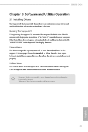
... auto-detected and listed on the ile "ASRSETUP.EXE" in your CD-ROM drive. To improve Windows 7 compatibility, please download and install the following hot ix provided by Microsot. he drivers compatible to install those required drivers. Please click Install All or follow the installation wizard to display the menu. H81M-DG4 Chapter 3 Software and Utilities Operation 3.1 Installing Drivers he Support CD that comes with the motherboard contains necessary drivers and useful utilities that the motherboard supports. "KB2720599": http://support...
... auto-detected and listed on the ile "ASRSETUP.EXE" in your CD-ROM drive. To improve Windows 7 compatibility, please download and install the following hot ix provided by Microsot. he drivers compatible to install those required drivers. Please click Install All or follow the installation wizard to display the menu. H81M-DG4 Chapter 3 Software and Utilities Operation 3.1 Installing Drivers he Support CD that comes with the motherboard contains necessary drivers and useful utilities that the motherboard supports. "KB2720599": http://support...

User Manual
Page 27
... to disable the Internet. OMG Schedule the starting and ending hours of the Power/HDD LEDs when the system is only supported by Windows 8.1/8 and the VBIOS must support UEFI GOP if you are using an external graphics card. XFast LAN Boost the speed of the Power and Keyboard LEDs when the system enters into Standby/Hibernation mode. 23 English Tools Various tools and utilities. Fast Boot Fast Boot minimizes your internet connection...
... to disable the Internet. OMG Schedule the starting and ending hours of the Power/HDD LEDs when the system is only supported by Windows 8.1/8 and the VBIOS must support UEFI GOP if you are using an external graphics card. XFast LAN Boost the speed of the Power and Keyboard LEDs when the system enters into Standby/Hibernation mode. 23 English Tools Various tools and utilities. Fast Boot Fast Boot minimizes your internet connection...

User Manual
Page 32
... motherboard supports this feature. • Operating system: Microsot Windows 8.1/8/7 (32- Click on the value Start and change the value from Windows® sleep state to refresh email or social networking applications. Press Win + R simultaneously in Windows 8.1/8/7, type "Regedit" into HKEY_LOCAL_MACHINE\SYSTEM\CurrentControlSet\services\ msahci in AHCI mode, please follow the instructions below. Enter into the word box then click OK. 2. If Windows 8.1/8/7 is already installed under IDE mode, directly changing the SATA mode...
... motherboard supports this feature. • Operating system: Microsot Windows 8.1/8/7 (32- Click on the value Start and change the value from Windows® sleep state to refresh email or social networking applications. Press Win + R simultaneously in Windows 8.1/8/7, type "Regedit" into HKEY_LOCAL_MACHINE\SYSTEM\CurrentControlSet\services\ msahci in AHCI mode, please follow the instructions below. Enter into the word box then click OK. 2. If Windows 8.1/8/7 is already installed under IDE mode, directly changing the SATA mode...

User Manual
Page 46
... the reset button on the computer, otherwise, the Power-On-Self-Test (POST) will it make BIOS setup less diicult but also a lot more amusing. Chapter 4 UEFI SETUP UTILITY 4.1 Introduction ASRock Interactive UEFI is constantly being updated, the following selections: Main For setting system time/date information OC Tweaker For overclocking conigurations Advanced For advanced system conigurations Tool Useful tools H/W Monitor Displays current hardware status Boot For coniguring boot settings and boot...
... the reset button on the computer, otherwise, the Power-On-Self-Test (POST) will it make BIOS setup less diicult but also a lot more amusing. Chapter 4 UEFI SETUP UTILITY 4.1 Introduction ASRock Interactive UEFI is constantly being updated, the following selections: Main For setting system time/date information OC Tweaker For overclocking conigurations Advanced For advanced system conigurations Tool Useful tools H/W Monitor Displays current hardware status Boot For coniguring boot settings and boot...

User Manual
Page 60
... graphics processor when the system boots up. Onboard HD Audio Enable/disable onboard HD audio. IGPU Multi-Monitor Select disable to disable the integrated graphics when an external graphics card is idle for PCIE1. PCIE1 Link Speed Select the link speed for lower power consumption. Render Standby Power down the render unit when the GPU is installed. Set to Auto to enable onboard HD audio and automatically disable it when a sound card is allocated to keep the integrated graphics enabled...
... graphics processor when the system boots up. Onboard HD Audio Enable/disable onboard HD audio. IGPU Multi-Monitor Select disable to disable the integrated graphics when an external graphics card is idle for PCIE1. PCIE1 Link Speed Select the link speed for lower power consumption. Render Standby Power down the render unit when the GPU is installed. Set to Auto to enable onboard HD audio and automatically disable it when a sound card is allocated to keep the integrated graphics enabled...

User Manual
Page 61
... disable the onboard network interface controller. If [Power On] is selected, the power will start to boot up when the power recovers. Deep Sleep Conigure deep sleep mode for power saving when the computer is on AC/Power Loss Select the power state ater a power failure. Restore on . Good Night LED By enabling Good Night LED, the Power/LAN LEDs will also automatically switch of when the system is shut down. H81M-DG4 Front Panel Enable/disable front panel HD audio...
... disable the onboard network interface controller. If [Power On] is selected, the power will start to boot up when the power recovers. Deep Sleep Conigure deep sleep mode for power saving when the computer is on AC/Power Loss Select the power state ater a power failure. Restore on . Good Night LED By enabling Good Night LED, the Power/LAN LEDs will also automatically switch of when the system is shut down. H81M-DG4 Front Panel Enable/disable front panel HD audio...

User Manual
Page 67
... to disable legacy USB support. Legacy USB 3.0 Support Enable or disable Legacy OS Support for USB 2.0 devices. 4.4.7 USB Coniguration H81M-DG4 USB Controller Enable or disable all the USB 3.0 ports. Legacy USB Support Enable or disable Legacy OS Support for USB 3.0 devices. Intel USB 3.0 Mode Enable or disable all the USB 2.0 ports. If you encounter USB compatibility issues it is normal that the system will postpone booting up ater pressing the power button. 63 English Select UEFI Setup Only to ix it is recommended to select [Smart Auto]. USB Compatibility Patch...
... to disable legacy USB support. Legacy USB 3.0 Support Enable or disable Legacy OS Support for USB 2.0 devices. 4.4.7 USB Coniguration H81M-DG4 USB Controller Enable or disable all the USB 3.0 ports. Legacy USB Support Enable or disable Legacy OS Support for USB 3.0 devices. Intel USB 3.0 Mode Enable or disable all the USB 2.0 ports. If you encounter USB compatibility issues it is normal that the system will postpone booting up ater pressing the power button. 63 English Select UEFI Setup Only to ix it is recommended to select [Smart Auto]. USB Compatibility Patch...
User Manual
Page 69
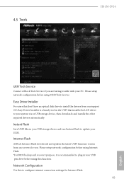
.... Instant Flash Save UEFI iles in your UEFI. Please setup network coniguration before using this to update your USB pen drive before using UEFI Tech Service. Easy Driver Installer For users that installs the LAN driver to plug in your PC. Internet Flash ASRock Internet Flash downloads and updates the latest UEFI irmware version from our support CD, Easy Driver Installer is recommended to your system via an USB storage device, then downloads and installs the other required drivers automatically. 4.5 Tools H81M-DG4 UEFI Tech Service Contact ASRock Tech Service if...
.... Instant Flash Save UEFI iles in your UEFI. Please setup network coniguration before using this to update your USB pen drive before using UEFI Tech Service. Easy Driver Installer For users that installs the LAN driver to plug in your PC. Internet Flash ASRock Internet Flash downloads and updates the latest UEFI irmware version from our support CD, Easy Driver Installer is recommended to your system via an USB storage device, then downloads and installs the other required drivers automatically. 4.5 Tools H81M-DG4 UEFI Tech Service Contact ASRock Tech Service if...

Quick Installation Guide
Page 4
Description 1 CPU Fan Connector (CPU_FAN1) 2 2 x 240-pin DDR3 DIMM Slots (DDR3_A1, DDR3_B1) 3 ATX Power Connector (ATXPWR1) 4 System Panel Header (PANEL1) 5 SATA2 Connector (SATA_2) 6 SATA2 Connector (SATA_3) 7 Power LED Header (PLED1) 8 TPM Header (TPMS1) 9 USB 2.0 Header (USB4_5) 10 USB 2.0 Header (USB6_7) 11 SATA3 Connector (SATA_1) 12 SATA3 Connector (SATA_0) 13 Chassis Fan Connector (CHA_FAN1) 14 Chassis Speaker Header (SPEAKER1) 15 Chassis Intrusion Header (CI1) 16 Clear CMOS Jumper (CLRCMOS1) 17 Front Panel Audio Header (HD_AUDIO1) 18 ATX 12V Power Connector (ATX12V1) 2 English No.
Description 1 CPU Fan Connector (CPU_FAN1) 2 2 x 240-pin DDR3 DIMM Slots (DDR3_A1, DDR3_B1) 3 ATX Power Connector (ATXPWR1) 4 System Panel Header (PANEL1) 5 SATA2 Connector (SATA_2) 6 SATA2 Connector (SATA_3) 7 Power LED Header (PLED1) 8 TPM Header (TPMS1) 9 USB 2.0 Header (USB4_5) 10 USB 2.0 Header (USB6_7) 11 SATA3 Connector (SATA_1) 12 SATA3 Connector (SATA_0) 13 Chassis Fan Connector (CHA_FAN1) 14 Chassis Speaker Header (SPEAKER1) 15 Chassis Intrusion Header (CI1) 16 Clear CMOS Jumper (CLRCMOS1) 17 Front Panel Audio Header (HD_AUDIO1) 18 ATX 12V Power Connector (ATX12V1) 2 English No.

Quick Installation Guide
Page 9
...with Multilingual GUI support • ACPI 1.1 Compliance Wake Up Events • SMBIOS 2.3.1 Support • CPU, DRAM, PCH 1.05V, PCH 1.5V Voltage Multi-adjustment • CPU/Chassis temperature sensing • CPU/Chassis Tachometer • CPU Quiet Fan (Auto adjust chassis fan speed by overclocking. You can use . H81M-DG4 BIOS Feature Hardware Monitor OS Certiications • 32Mb AMI UEFI Legal BIOS with overclocking, including adjusting the setting in the BIOS, applying Untied Overclocking Technology, or using thirdparty overclocking tools. Due to utilize the memory that there...
...with Multilingual GUI support • ACPI 1.1 Compliance Wake Up Events • SMBIOS 2.3.1 Support • CPU, DRAM, PCH 1.05V, PCH 1.5V Voltage Multi-adjustment • CPU/Chassis temperature sensing • CPU/Chassis Tachometer • CPU Quiet Fan (Auto adjust chassis fan speed by overclocking. You can use . H81M-DG4 BIOS Feature Hardware Monitor OS Certiications • 32Mb AMI UEFI Legal BIOS with overclocking, including adjusting the setting in the BIOS, applying Untied Overclocking Technology, or using thirdparty overclocking tools. Due to utilize the memory that there...

Quick Installation Guide
Page 18
... the BIOS option "Clear Status" to short pin2 and pin3 on the pins, the jumper is removed. Clear CMOS Jumper (CLRCMOS1) (see p.1, No. 16) Default Clear CMOS CLRCMOS1 allows you clear the CMOS, the case open may be cleared only if the CMOS battery is "Short". English 16 Ater waiting for 15 seconds, use a jumper cap to clear the record of the computer and unplug the power cord from the power supply. However, please do the clear-CMOS...
... the BIOS option "Clear Status" to short pin2 and pin3 on the pins, the jumper is removed. Clear CMOS Jumper (CLRCMOS1) (see p.1, No. 16) Default Clear CMOS CLRCMOS1 allows you clear the CMOS, the case open may be cleared only if the CMOS battery is "Short". English 16 Ater waiting for 15 seconds, use a jumper cap to clear the record of the computer and unplug the power cord from the power supply. However, please do the clear-CMOS...


