User Manual
Page 2
With respect to the contents of this manual, ASRock does not provide warranty of any kind, either expressed or implied, including but not limited to infringe. CALIFORNIA, USA ONLY The Lithium battery adopted on this motherboard contains Perchlorate, a toxic substance controlled in ...advance. Products and corporate names appearing in this manual may or may not be constructed as a commitment by ASRock. ASRock assumes no event shall ASRock, its directors, officers, employees...
With respect to the contents of this manual, ASRock does not provide warranty of any kind, either expressed or implied, including but not limited to infringe. CALIFORNIA, USA ONLY The Lithium battery adopted on this motherboard contains Perchlorate, a toxic substance controlled in ...advance. Products and corporate names appearing in this manual may or may not be constructed as a commitment by ASRock. ASRock assumes no event shall ASRock, its directors, officers, employees...
User Manual
Page 3
Contents 1 Introduction 5 1.1 Package Contents 5 1.2 Specifications 6 1.3 Motherboard Layout (H61M-GS / H61M-S 11 1.4 I/O Panel (H61M-GS 12 1.5 I/O Panel (H61M-S 13 2 Installation 14 2.1 Screw Holes 14 2.2 Pre-installation Precautions 14 2.3 CPU Installation 15 2.4 Installation of Heatsink and CPU fan 17 2.5 Installation of Memory Modules (DIMM ...
Contents 1 Introduction 5 1.1 Package Contents 5 1.2 Specifications 6 1.3 Motherboard Layout (H61M-GS / H61M-S 11 1.4 I/O Panel (H61M-GS 12 1.5 I/O Panel (H61M-S 13 2 Installation 14 2.1 Screw Holes 14 2.2 Pre-installation Precautions 14 2.3 CPU Installation 15 2.4 Installation of Heatsink and CPU fan 17 2.5 Installation of Memory Modules (DIMM ...
User Manual
Page 5
... BIOS software might be updated, the content of the motherboard and stepby-step guide to change without further notice. www.asrock.com/support/index.asp 1.1 Package Contents ASRock H61M-GS / H61M-S Motherboard (Micro ATX Form Factor: 9.6-in x 7.8-in our support CD for purchasing ASRock H61M-GS / H61M-S motherboard, a reliable motherboard produced under ASRock's consistently stringent quality control. To get better performance in...
... BIOS software might be updated, the content of the motherboard and stepby-step guide to change without further notice. www.asrock.com/support/index.asp 1.1 Package Contents ASRock H61M-GS / H61M-S Motherboard (Micro ATX Form Factor: 9.6-in x 7.8-in our support CD for purchasing ASRock H61M-GS / H61M-S motherboard, a reliable motherboard produced under ASRock's consistently stringent quality control. To get better performance in...

User Manual
Page 8
... phases to improve efficiency when the CPU cores are allowed to the components and devices of ASRock Extreme Tuning Utility (AXTU). ASRock website: http://www.asrock.com 8 We are not responsible for proper installation. 3. In OC DNA, you are idle without sacrificing...to overclock CPU frequency for system usage under Windows® 7 / VistaTM / XP. This motherboard supports Dual Channel Memory Technology. The maximum shared memory size is defined by overclocking. ASRock Extreme Tuning Utility (AXTU) is an all-in a user-friendly interface, which is a...
... phases to improve efficiency when the CPU cores are allowed to the components and devices of ASRock Extreme Tuning Utility (AXTU). ASRock website: http://www.asrock.com 8 We are not responsible for proper installation. 3. In OC DNA, you are idle without sacrificing...to overclock CPU frequency for system usage under Windows® 7 / VistaTM / XP. This motherboard supports Dual Channel Memory Technology. The maximum shared memory size is defined by overclocking. ASRock Extreme Tuning Utility (AXTU) is an all-in a user-friendly interface, which is a...
User Manual
Page 9
...setup menu to update system BIOS without preparing an additional floppy diskette or other complicated flash utility. ASRock motherboards are exclusively equipped with friends on the property of PC gaming operation. With APP Charger driver installed, you to access...continuous charging when your Apple devices, such as a game joystick to your motherboard, and also download the free AIWI Lite from ASRock of ficial website regularly, we will continuously provide you - ASRock website: http://www.asrock.com/Feature/Aiwi/index.asp 8. To use FAT32/16/12 file...
...setup menu to update system BIOS without preparing an additional floppy diskette or other complicated flash utility. ASRock motherboards are exclusively equipped with friends on the property of PC gaming operation. With APP Charger driver installed, you to access...continuous charging when your Apple devices, such as a game joystick to your motherboard, and also download the free AIWI Lite from ASRock of ficial website regularly, we will continuously provide you - ASRock website: http://www.asrock.com/Feature/Aiwi/index.asp 8. To use FAT32/16/12 file...
User Manual
Page 10
... According to spray thermal grease between the CPU and the heatsink when you resume the system, please check if the CPU fan on the motherboard functions properly and unplug the power cord, then plug it back again. Before you install the PC system. 12. To meet the standard... off mode condition. To improve heat dissipation, remember to Intel's suggestion, the EuP ready power supply must meet EuP standard, an EuP ready motherboard and an EuP ready power supply are required. EuP, stands for Energy Using Product, was a provision regulated by European Union to adopt three different...
... According to spray thermal grease between the CPU and the heatsink when you resume the system, please check if the CPU fan on the motherboard functions properly and unplug the power cord, then plug it back again. Before you install the PC system. 12. To meet the standard... off mode condition. To improve heat dissipation, remember to Intel's suggestion, the EuP ready power supply must meet EuP standard, an EuP ready motherboard and an EuP ready power supply are required. EuP, stands for Energy Using Product, was a provision regulated by European Union to adopt three different...
User Manual
Page 11
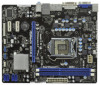
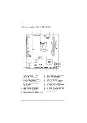
1.3 Motherboard Layout (H61M-GS / H61M-S) PS2 Mouse PS2 Keyboard 1 23 4 5 19.8cm (7.8 in) Designed in Taipei ErP/EuP Ready CPU_FAN1 ATX12V1 DX10.1 VGA1 24.4cm (9.6 in) DDR3 ATXPWR1 DDR3_B1 (64 ...
1.3 Motherboard Layout (H61M-GS / H61M-S) PS2 Mouse PS2 Keyboard 1 23 4 5 19.8cm (7.8 in) Designed in Taipei ErP/EuP Ready CPU_FAN1 ATX12V1 DX10.1 VGA1 24.4cm (9.6 in) DDR3 ATXPWR1 DDR3_B1 (64 ...
User Manual
Page 14
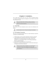
...remember to use a grounded wrist strap or touch a safety grounded object before you install the motherboard, study the configuration of the following precautions before you and damages to motherboard components. 2.1 Screw Holes Place screws into the holes indicated by the edges and do so ...the power cord is a Micro ATX form factor (9.6" x 7.8", 24.4 x 19.8 cm) motherboard. To avoid damaging the motherboard components due to unplug the power cord before installing or removing the motherboard. Doing so may cause physical injuries to the chassis. Failure to do so may damage the...
...remember to use a grounded wrist strap or touch a safety grounded object before you install the motherboard, study the configuration of the following precautions before you and damages to motherboard components. 2.1 Screw Holes Place screws into the holes indicated by the edges and do so ...the power cord is a Micro ATX form factor (9.6" x 7.8", 24.4 x 19.8 cm) motherboard. To avoid damaging the motherboard components due to unplug the power cord before installing or removing the motherboard. Doing so may cause physical injuries to the chassis. Failure to do so may damage the...

User Manual
Page 15
... into the socket, please check if the CPU surface is unclean or if there is found. Otherwise, the CPU will be placed if returning the motherboard for after service. 15 It is recommended to use the cap tab to clear retention tab. 2.3 CPU Installation For the installation of Intel 1155-Pin...
... into the socket, please check if the CPU surface is unclean or if there is found. Otherwise, the CPU will be placed if returning the motherboard for after service. 15 It is recommended to use the cap tab to clear retention tab. 2.3 CPU Installation For the installation of Intel 1155-Pin...
User Manual
Page 17
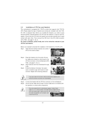
...to dissipate heat. Rotate the fastener clockwise, then press down the fasteners without rotating them clockwise, the heatsink cannot be noticed that this motherboard supports Combo Cooler Option (C.C.O.), which provides the flexible option to adopt three different CPU cooler types, Socket LGA 775, LGA ... the CPU and the heatsink are securely fastened and in good contact with remaining fasteners. 2.4 Installation of CPU Fan and Heatsink This motherboard is an example to illustrate the installation of the heatsink for Socket LGA 1155/1156 CPU fan. 17 Step 5. Step 6. Apply ...
...to dissipate heat. Rotate the fastener clockwise, then press down the fasteners without rotating them clockwise, the heatsink cannot be noticed that this motherboard supports Combo Cooler Option (C.C.O.), which provides the flexible option to adopt three different CPU cooler types, Socket LGA 775, LGA ... the CPU and the heatsink are securely fastened and in good contact with remaining fasteners. 2.4 Installation of CPU Fan and Heatsink This motherboard is an example to illustrate the installation of the heatsink for Socket LGA 1155/1156 CPU fan. 17 Step 5. Step 6. Apply ...

User Manual
Page 18
... the slot at both ends fully snap back in one memory module or two non-identical memory modules, it will cause permanent damage to the motherboard and the DIMM if you always need to install two identical (the same brand, speed, size and chiptype) memory modules in the DDR3 DIMM ... adding or removing DIMMs or the system components. Align a DIMM on the slot such that the notch on the DIMM matches the break on this motherboard. Unlock a DIMM slot by pressing the retaining clips outward. For dual channel configuration, you force the DIMM into the slot until the retaining clips at...
... the slot at both ends fully snap back in one memory module or two non-identical memory modules, it will cause permanent damage to the motherboard and the DIMM if you always need to install two identical (the same brand, speed, size and chiptype) memory modules in the DDR3 DIMM ... adding or removing DIMMs or the system components. Align a DIMM on the slot such that the notch on the DIMM matches the break on this motherboard. Unlock a DIMM slot by pressing the retaining clips outward. For dual channel configuration, you force the DIMM into the slot until the retaining clips at...
User Manual
Page 19
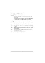
PCIE2 / PCIE3 (PCIE x1 slot; Step 2. Remove the system unit cover (if your motherboard is used for the card before you intend to the chassis with screws. 2.6 Expansion Slots (PCI Express Slots) There are 3 PCI Express slots on the ... expansion card Step 1. Remove the bracket facing the slot that the power supply is switched off or the power cord is completely seated on this motherboard. Align the card connector with x1 lane width cards, such as Gigabit LAN card, SATA2 card, etc. PCIE slots: PCIE1 (PCIE x16 slot; Please read...
PCIE2 / PCIE3 (PCIE x1 slot; Step 2. Remove the system unit cover (if your motherboard is used for the card before you intend to the chassis with screws. 2.6 Expansion Slots (PCI Express Slots) There are 3 PCI Express slots on the ... expansion card Step 1. Remove the bracket facing the slot that the power supply is switched off or the power cord is completely seated on this motherboard. Align the card connector with x1 lane width cards, such as Gigabit LAN card, SATA2 card, etc. PCIE slots: PCIE1 (PCIE x16 slot; Please read...
User Manual
Page 20
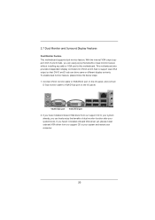
... on the I/O panel, and connect D-Sub monitor cable to VGA/D-Sub port on VGA card to this motherboard. 2.7 Dual Monitor and Surround Display Features Dual Monitor Feature This motherboard supports dual monitor feature. To enable dual monitor feature, please follow the below steps: 1. With the internal... function after your computer. 20 VGA/D-Sub port VGA/DVI-D port 2. If you can drive same or different display contents. This motherboard also provides independent display controllers for DVI-D and D-Sub to your system and restart your system boots. If you have installed onboard ...
... on the I/O panel, and connect D-Sub monitor cable to VGA/D-Sub port on VGA card to this motherboard. 2.7 Dual Monitor and Surround Display Features Dual Monitor Feature This motherboard supports dual monitor feature. To enable dual monitor feature, please follow the below steps: 1. With the internal... function after your computer. 20 VGA/D-Sub port VGA/DVI-D port 2. If you can drive same or different display contents. This motherboard also provides independent display controllers for DVI-D and D-Sub to your system and restart your system boots. If you have installed onboard ...

User Manual
Page 21
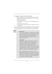
Surround Display Feature This motherboard supports surround display upgrade. Please refer to the following steps to enter UEFI setup. Connect DVI-D monitor cable to VGA/DVI-D port on the I /O panel. ... display a large number on the I /O panel, and connect D-Sub monitor cable to VGA/D-Sub port on each monitor. Click "Extend my Windows desktop onto this motherboard. 4. E. Right-click the display icon and select "Attached", if necessary. G. Click the "Identify" button to the steps below. Right-click the display icon in the...
Surround Display Feature This motherboard supports surround display upgrade. Please refer to the following steps to enter UEFI setup. Connect DVI-D monitor cable to VGA/DVI-D port on the I /O panel. ... display a large number on the I /O panel, and connect D-Sub monitor cable to VGA/D-Sub port on each monitor. Click "Extend my Windows desktop onto this motherboard. 4. E. Right-click the display icon and select "Attached", if necessary. G. Click the "Identify" button to the steps below. Right-click the display icon in the...
User Manual
Page 22
...A through C for more details about HDCP function. Click and drag the display icons to use. To use HDCP function with this motherboard, you need to adopt the monitor that you would like to positions representing the physical setup of intercepting digital data midstream between the video...to save your monitors that supports HDCP function as well. HDCP Function HDCP function is my main monitor" and "Extend the desktop onto this motherboard. HDCP stands for High-Bandwidth Digital Content Protection, a specification developed by the number three and four. 6. D. Due to ...
...A through C for more details about HDCP function. Click and drag the display icons to use. To use HDCP function with this motherboard, you need to adopt the monitor that you would like to positions representing the physical setup of intercepting digital data midstream between the video...to save your monitors that supports HDCP function as well. HDCP Function HDCP function is my main monitor" and "Extend the desktop onto this motherboard. HDCP stands for High-Bandwidth Digital Content Protection, a specification developed by the number three and four. 6. D. Due to ...
User Manual
Page 24
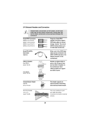
The current SATAII interface allows up to the SATA / SATAII hard disk or the SATAII connector on this motherboard. Infrared Module Header (5-pin IR1) (see p.11 No. 20) AFD# ERROR# PINIT# SLIN# GND 1 SPD7 SPD6 ACK# SPD5 BUSY SPD4 PE SPD3.... 12) SATA2_0 SATA2_1 SATA2_2 SATA2_3 These four Serial ATAII (SATAII) connectors support SATA data cables for print port cable that allows convenient connection of the motherboard! Serial ATAII Connectors (SATA2_0: see p.11, No. 9) (SATA2_1: see p.11, No. 10) (SATA2_2: see p.11, No. 11) (SATA2_3: see p.11 No. 16) USB_PWR P-9...
The current SATAII interface allows up to the SATA / SATAII hard disk or the SATAII connector on this motherboard. Infrared Module Header (5-pin IR1) (see p.11 No. 20) AFD# ERROR# PINIT# SLIN# GND 1 SPD7 SPD6 ACK# SPD5 BUSY SPD4 PE SPD3.... 12) SATA2_0 SATA2_1 SATA2_2 SATA2_3 These four Serial ATAII (SATAII) connectors support SATA data cables for print port cable that allows convenient connection of the motherboard! Serial ATAII Connectors (SATA2_0: see p.11, No. 9) (SATA2_1: see p.11, No. 10) (SATA2_2: see p.11, No. 11) (SATA2_3: see p.11 No. 16) USB_PWR P-9...
User Manual
Page 26
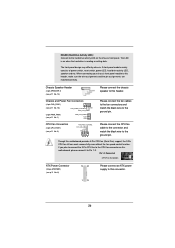
When connecting your chassis front panel module to this motherboard, please connect it to Pin 1-3. Chassis and Power Fan Connectors (4-pin CHA_FAN1) (see p.11 No. 18) FAN_SPEED_CONTROL GND +12V CHA_FAN_SPEED (3-pin PWR_FAN1) (see p.11 No. 3) ... the ground pin. Pin 1-3 Connected 3-Pin Fan Installation ATX Power Connector (24-pin ATXPWR1) (see p.11 No. 13) Please connect the chassis speaker to this motherboard provides 4-Pin CPU fan (Quiet Fan) support, the 3-Pin CPU fan still can work successfully even without the fan speed control function. The front panel...
When connecting your chassis front panel module to this motherboard, please connect it to Pin 1-3. Chassis and Power Fan Connectors (4-pin CHA_FAN1) (see p.11 No. 18) FAN_SPEED_CONTROL GND +12V CHA_FAN_SPEED (3-pin PWR_FAN1) (see p.11 No. 3) ... the ground pin. Pin 1-3 Connected 3-Pin Fan Installation ATX Power Connector (24-pin ATXPWR1) (see p.11 No. 13) Please connect the chassis speaker to this motherboard provides 4-Pin CPU fan (Quiet Fan) support, the 3-Pin CPU fan still can work successfully even without the fan speed control function. The front panel...
User Manual
Page 27
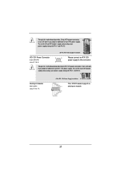
... along with Pin 1 and Pin 5. 8 5 Serial port Header (9-pin COM1) (see p.11 No. 4) 8 5 4 1 Please connect an ATX 12V power supply to this connector. Though this motherboard provides 8-pin ATX 12V power connector, it can still work if you adopt a traditional 4-pin ATX 12V power supply. Though this... motherboard provides 24-pin ATX power connector, 12 24 it can still work if you adopt a traditional 20-pin ATX power supply. To use the 4-pin ...
... along with Pin 1 and Pin 5. 8 5 Serial port Header (9-pin COM1) (see p.11 No. 4) 8 5 4 1 Please connect an ATX 12V power supply to this connector. Though this motherboard provides 8-pin ATX 12V power connector, it can still work if you adopt a traditional 4-pin ATX 12V power supply. Though this... motherboard provides 24-pin ATX power connector, 12 24 it can still work if you adopt a traditional 20-pin ATX power supply. To use the 4-pin ...
User Manual
Page 28
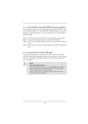
... disks on and in AHCI mode. This section will guide you to the SATA / SATAII hard disk. nector. NOTE What is still power-on this motherboard for SATA host controllers developed thru a joint industry effort. STEP 2: Connect the SATA power cable to install the SATA / SATAII hard disks. However, please ... into the drive bays of the SATA data cable to the SATA / SATAII hard disk. 2.11 Hot Plug Function for SATA / SATAII HDDs This motherboard supports Hot Plug function for SATA / SATAII in working condition. 2.10 Serial ATA (SATA) / Serial ATAII (SATAII) Hard Disks Installation This...
... disks on and in AHCI mode. This section will guide you to the SATA / SATAII hard disk. nector. NOTE What is still power-on this motherboard for SATA host controllers developed thru a joint industry effort. STEP 2: Connect the SATA power cable to install the SATA / SATAII hard disks. However, please ... into the drive bays of the SATA data cable to the SATA / SATAII hard disk. 2.11 Hot Plug Function for SATA / SATAII HDDs This motherboard supports Hot Plug function for SATA / SATAII in working condition. 2.10 Serial ATA (SATA) / Serial ATAII (SATAII) Hard Disks Installation This...
User Manual
Page 29
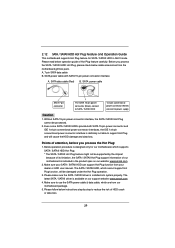
... you process the SATA / SATAII HDD Hot Plug, please check below operation guide of our motherboard is designed only for SATA / SATAII HDD in the product spec on our support website: www.asrock.com 4. A. 7-pin SATA data cable B. Without SATA 15-pin power connector interface, the...is available on our website: www.asrock.com 2. Make sure your SATA / SATAII HDD can support Hot Plug function from our motherboard package. 5. 2.12 SATA / SATAII HDD Hot Plug Feature and Operation Guide This motherboard supports Hot Plug feature for our motherboard, which are from your dealer or...
... you process the SATA / SATAII HDD Hot Plug, please check below operation guide of our motherboard is designed only for SATA / SATAII HDD in the product spec on our support website: www.asrock.com 4. A. 7-pin SATA data cable B. Without SATA 15-pin power connector interface, the...is available on our website: www.asrock.com 2. Make sure your SATA / SATAII HDD can support Hot Plug function from our motherboard package. 5. 2.12 SATA / SATAII HDD Hot Plug Feature and Operation Guide This motherboard supports Hot Plug feature for our motherboard, which are from your dealer or...


