User Manual
Page 10
..., an EuP ready motherboard and an EuP ready power supply are required. To improve heat dissipation, remember to adopt three different CPU cooler types, Socket LGA 775, LGA 1155 and LGA 1156. Combo Cooler Option (C.C.O.) provides the flexible option to spray thermal grease between the CPU and the heatsink when you...
..., an EuP ready motherboard and an EuP ready power supply are required. To improve heat dissipation, remember to adopt three different CPU cooler types, Socket LGA 775, LGA 1155 and LGA 1156. Combo Cooler Option (C.C.O.) provides the flexible option to spray thermal grease between the CPU and the heatsink when you...
User Manual
Page 11
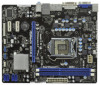
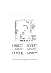
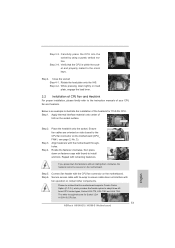
1.3 Motherboard Layout (H61M-GS / H61M-S) PS2 Mouse PS2 Keyboard 1 23 4 5 19.8cm (7.8 in) Designed in Taipei ErP/EuP Ready CPU_FAN1 ATX12V1 DX10.1 VGA1 24.4cm (9.6 in) DDR3 ATXPWR1 DDR3_B1 (64 ... 1 SATA2_3 Dual Channel 6 7 8 9 10 11 21 20 1918 17 16 15 14 13 12 1 Power Fan Connector (PWR_FAN1) 14 System Panel Header (PANEL1, White) 2 1155-Pin CPU Socket 15 USB 2.0 Header (USB6_7, Blue) 3 CPU Fan Connector (CPU_FAN1) 16 USB 2.0 Header (USB8_9, Blue) 4 ATX 12V Power Connector (ATX12V1 17 COM Port Header (COM1...
1.3 Motherboard Layout (H61M-GS / H61M-S) PS2 Mouse PS2 Keyboard 1 23 4 5 19.8cm (7.8 in) Designed in Taipei ErP/EuP Ready CPU_FAN1 ATX12V1 DX10.1 VGA1 24.4cm (9.6 in) DDR3 ATXPWR1 DDR3_B1 (64 ... 1 SATA2_3 Dual Channel 6 7 8 9 10 11 21 20 1918 17 16 15 14 13 12 1 Power Fan Connector (PWR_FAN1) 14 System Panel Header (PANEL1, White) 2 1155-Pin CPU Socket 15 USB 2.0 Header (USB6_7, Blue) 3 CPU Fan Connector (CPU_FAN1) 16 USB 2.0 Header (USB8_9, Blue) 4 ATX 12V Power Connector (ATX12V1 17 COM Port Header (COM1...

User Manual
Page 15
Step 1-2. Remove PnP Cap (Pick and Place Cap). 1. Step 1. Disengaging the lever by depressing down and out on the socket. Rotate the load lever to clear retention tab. Step 2. It is recommended to use the cap tab to fully open position at approximately 100 degrees.... check if the CPU surface is unclean or if there is found. Load Plate Load Lever Contact Array Socket Body 1155-Pin Socket Overview Before you insert the 1155-Pin CPU into the socket if above situation is any bent pin on the hook to fully open position at approximately 135 degrees. 2.3 CPU Installation For...
Step 1-2. Remove PnP Cap (Pick and Place Cap). 1. Step 1. Disengaging the lever by depressing down and out on the socket. Rotate the load lever to clear retention tab. Step 2. It is recommended to use the cap tab to fully open position at approximately 100 degrees.... check if the CPU surface is unclean or if there is found. Load Plate Load Lever Contact Array Socket Body 1155-Pin Socket Overview Before you insert the 1155-Pin CPU into the socket if above situation is any bent pin on the hook to fully open position at approximately 135 degrees. 2.3 CPU Installation For...
User Manual
Page 16
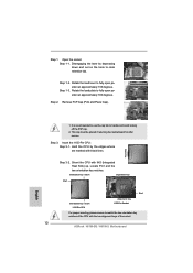
... 3-4. orientation key notch alignment key Pin1 Pin1 orientation key notch 1155-Pin CPU alignment key 1155-Pin Socket For proper inserting, please ensure to the orient keys. Verify that the CPU is marked with black line. Step 3. Insert the 1155-Pin CPU: Step 3-1. While pressing down lightly on load plate... Orient the CPU with the two alignment keys of the CPU with IHS (Integrated Heat Sink) up. Close the socket: Step 4-1. Carefully place the CPU into the socket by the edge where is within the socket and properly mated to match the two orientation key notches of the...
... 3-4. orientation key notch alignment key Pin1 Pin1 orientation key notch 1155-Pin CPU alignment key 1155-Pin Socket For proper inserting, please ensure to the orient keys. Verify that the CPU is marked with black line. Step 3. Insert the 1155-Pin CPU: Step 3-1. While pressing down lightly on load plate... Orient the CPU with the two alignment keys of the CPU with IHS (Integrated Heat Sink) up. Close the socket: Step 4-1. Carefully place the CPU into the socket by the edge where is within the socket and properly mated to match the two orientation key notches of the...
User Manual
Page 17
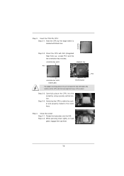
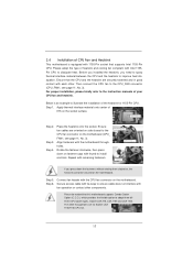
...excess cable with tie-wrap to dissipate heat. For proper installation, please kindly refer to illustrate the installation of the heatsink for Socket LGA 1155/1156 CPU fan. 17 Connect fan header with fan operation or contact other . Below is equipped with remaining fasteners. Place the ...good contact with the motherboard throughholes. Then connect the CPU fan to improve heat dissipation. Step 3. Repeat with 1155-Pin socket that the CPU and the heatsink are for 1155-Pin CPU. Step 4. Step 1. 2.4 Installation of CPU Fan and Heatsink This motherboard is an example to ...
...excess cable with tie-wrap to dissipate heat. For proper installation, please kindly refer to illustrate the installation of the heatsink for Socket LGA 1155/1156 CPU fan. 17 Connect fan header with fan operation or contact other . Below is equipped with remaining fasteners. Place the ...good contact with the motherboard throughholes. Then connect the CPU fan to improve heat dissipation. Step 3. Repeat with 1155-Pin socket that the CPU and the heatsink are for 1155-Pin CPU. Step 4. Step 1. 2.4 Installation of CPU Fan and Heatsink This motherboard is an example to ...

Quick Installation Guide
Page 2
Motherboard Layout (H61M-GS / H61M-S) PS2 Mouse PS2 Keyboard 1 23 4 5 19.8cm (7.8 in) Designed in Taipei ErP/EuP Ready CPU_FAN1 ATX12V1 DX10... 8 9 10 11 21 20 1918 17 16 15 14 13 12 1 Power Fan Connector (PWR_FAN1) 14 System Panel Header (PANEL1, White) 2 1155-Pin CPU Socket 15 USB 2.0 Header (USB6_7, Blue) 3 CPU Fan Connector (CPU_FAN1) 16 USB 2.0 Header (USB8_9, Blue) 4 ATX 12V Power Connector (ATX12V1 17...Panel Audio Header 12 SATA2 Connector (SATA2_3, Blue) (HD_AUDIO1, White) 13 Chassis Speaker Header (SPEAKER 1, White) English 2 ASRock H61M-GS / H61M-S Motherboard
Motherboard Layout (H61M-GS / H61M-S) PS2 Mouse PS2 Keyboard 1 23 4 5 19.8cm (7.8 in) Designed in Taipei ErP/EuP Ready CPU_FAN1 ATX12V1 DX10... 8 9 10 11 21 20 1918 17 16 15 14 13 12 1 Power Fan Connector (PWR_FAN1) 14 System Panel Header (PANEL1, White) 2 1155-Pin CPU Socket 15 USB 2.0 Header (USB6_7, Blue) 3 CPU Fan Connector (CPU_FAN1) 16 USB 2.0 Header (USB8_9, Blue) 4 ATX 12V Power Connector (ATX12V1 17...Panel Audio Header 12 SATA2 Connector (SATA2_3, Blue) (HD_AUDIO1, White) 13 Chassis Speaker Header (SPEAKER 1, White) English 2 ASRock H61M-GS / H61M-S Motherboard

Quick Installation Guide
Page 10
... you checking with the power supply manufacturer for Energy Using Product, was a provision regulated by European Union to adopt three different CPU cooler types, Socket LGA 775, LGA 1155 and LGA 1156. Combo Cooler Option (C.C.O.) provides the flexible option to define the power consumption for the completed system. 11... EuP ready power supply are required. While CPU overheat is higher than 50% under 1.00W in off mode condition. EuP, stands for more details. 10 ASRock H61M-GS / H61M-S Motherboard English
... you checking with the power supply manufacturer for Energy Using Product, was a provision regulated by European Union to adopt three different CPU cooler types, Socket LGA 775, LGA 1155 and LGA 1156. Combo Cooler Option (C.C.O.) provides the flexible option to define the power consumption for the completed system. 11... EuP ready power supply are required. While CPU overheat is higher than 50% under 1.00W in off mode condition. EuP, stands for more details. 10 ASRock H61M-GS / H61M-S Motherboard English

Quick Installation Guide
Page 11
...5. English 11 ASRock H61M-GS / H61M-S Motherboard Doing so may cause severe damage to do so may damage the motherboard. 2.1 CPU Installation For the installation of the following precautions before touching any motherboard settings. 1. Load Plate Contact Array Load Lever Socket Body 1155-Pin Socket Overview Before you...will be seriously damaged. erboard to use a grounded wrist strap or touch a safety grounded object before you insert the 1155-Pin CPU into the socket, please check if the CPU surface is unclean or if there is found. 2. Also remember to the chassis, ...
...5. English 11 ASRock H61M-GS / H61M-S Motherboard Doing so may cause severe damage to do so may damage the motherboard. 2.1 CPU Installation For the installation of the following precautions before touching any motherboard settings. 1. Load Plate Contact Array Load Lever Socket Body 1155-Pin Socket Overview Before you...will be seriously damaged. erboard to use a grounded wrist strap or touch a safety grounded object before you insert the 1155-Pin CPU into the socket, please check if the CPU surface is unclean or if there is found. 2. Also remember to the chassis, ...
Quick Installation Guide
Page 12
... open position at approximately 135 degrees. It is recommended to use the cap tab to match the two orientation key notches of the socket. 12 ASRock H61M-GS / H61M-S Motherboard Insert the 1155-Pin CPU: Step 3-1. Rotate the load lever to fully open position at approximately 100 degrees. black line English 1. This cap must be...
... open position at approximately 135 degrees. It is recommended to use the cap tab to match the two orientation key notches of the socket. 12 ASRock H61M-GS / H61M-S Motherboard Insert the 1155-Pin CPU: Step 3-1. Rotate the load lever to fully open position at approximately 100 degrees. black line English 1. This cap must be...
Quick Installation Guide
Page 13
... CPU Fan and Heatsink For proper installation, please kindly refer to adopt three different CPU cooler types, Socket LGA 775, LGA 1155 and LGA 1156. Below is within the socket and properly mated to MB header Fastener slots pointing straight out Press Down (4 Places) If you press...-wrap to illustrate the installation of IHS on the motherboard. Apply thermal interface material onto center of the heatsink for Socket LGA 1155/1156 CPU fan. 13 ASRock H61M-GS / H61M-S Motherboard English Fan cables on side closest to the orient keys. Step 5. Step 6. Secure excess cable with fan...
... CPU Fan and Heatsink For proper installation, please kindly refer to adopt three different CPU cooler types, Socket LGA 775, LGA 1155 and LGA 1156. Below is within the socket and properly mated to MB header Fastener slots pointing straight out Press Down (4 Places) If you press...-wrap to illustrate the installation of IHS on the motherboard. Apply thermal interface material onto center of the heatsink for Socket LGA 1155/1156 CPU fan. 13 ASRock H61M-GS / H61M-S Motherboard English Fan cables on side closest to the orient keys. Step 5. Step 6. Secure excess cable with fan...