User Manual
Page 3
... Motherboard Layout 11 1.4 I/O Panel 12 2 Installation 13 2.1 Screw Holes 13 2.2 Pre-installation Precautions 13 2.3 CPU Installation 14 2.4 Installation of Heatsink and CPU fan 16 2.5 Installation of Memory Modules (DIMM 17 2.6 Expansion Slots (PCI and PCI Express Slots 18 2.7 Multi Monitor Feature 19 2.8 Jumpers Setup 21 2.9 Onboard Headers and Connectors 22 2.10 Serial ATA (SATA) / Serial ATAII (SATAII) Hard Disks Installation 26 2.11 Hot Plug Function for SATA / SATAII HDDs 26 2.12 SATA / SATAII HDD Hot Plug Feature and Operation Guide 27 2.13 Driver Installation Guide 29...
... Motherboard Layout 11 1.4 I/O Panel 12 2 Installation 13 2.1 Screw Holes 13 2.2 Pre-installation Precautions 13 2.3 CPU Installation 14 2.4 Installation of Heatsink and CPU fan 16 2.5 Installation of Memory Modules (DIMM 17 2.6 Expansion Slots (PCI and PCI Express Slots 18 2.7 Multi Monitor Feature 19 2.8 Jumpers Setup 21 2.9 Onboard Headers and Connectors 22 2.10 Serial ATA (SATA) / Serial ATAII (SATAII) Hard Disks Installation 26 2.11 Hot Plug Function for SATA / SATAII HDDs 26 2.12 SATA / SATAII HDD Hot Plug Feature and Operation Guide 27 2.13 Driver Installation Guide 29...
User Manual
Page 5
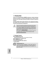
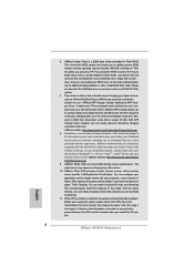
... and the BIOS software might be updated, the content of the Support CD. For the BIOS setup, please refer to BIOS setup and information of this motherboard, please visit our website for purchasing ASRock H61M-PS motherboard, a reliable motherboard produced under ASRock's consistently stringent quality control. Chapter 3 and 4 contain the configuration guide to the "User Manual" in , 24.4 cm x 19.8 cm) ASRock H61M-PS Quick Installation Guide ASRock H61M-PS Support CD 2 x Serial ATA (SATA) Data Cables (Optional) 1 x I/O Panel Shield ASRock Reminds...
... and the BIOS software might be updated, the content of the Support CD. For the BIOS setup, please refer to BIOS setup and information of this motherboard, please visit our website for purchasing ASRock H61M-PS motherboard, a reliable motherboard produced under ASRock's consistently stringent quality control. Chapter 3 and 4 contain the configuration guide to the "User Manual" in , 24.4 cm x 19.8 cm) ASRock H61M-PS Quick Installation Guide ASRock H61M-PS Support CD 2 x Serial ATA (SATA) Data Cables (Optional) 1 x I/O Panel Shield ASRock Reminds...
User Manual
Page 7
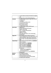
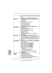
...Guard (B.F.G.) - Chassis Temperature Sensing - CPU/Chassis/Power Fan Tachometer - Hybrid Booster: - CPU Temperature Sensing - HD Audio Jack: Line in/Front Speaker/Microphone - 4 x SATA2 3.0 Gb/s connectors, support NCQ, AHCI and Hot Plug functions - 1 x IR header - CPU/Chassis/Power FAN connector - 24 pin ATX power connector - 8 pin 12V power connector - AMI UEFI Legal BIOS with LED (ACT/LINK LED and SPEED LED) - ASRock Instant Boot - ASRock SmartView (see CAUTION 7) - ASRock XFast USB (see CAUTION 6) - Supports jumperfree - IGPU, DRAM, PCH, CPU PLL, VTT, VCCSA Voltage Multi...
...Guard (B.F.G.) - Chassis Temperature Sensing - CPU/Chassis/Power Fan Tachometer - Hybrid Booster: - CPU Temperature Sensing - HD Audio Jack: Line in/Front Speaker/Microphone - 4 x SATA2 3.0 Gb/s connectors, support NCQ, AHCI and Hot Plug functions - 1 x IR header - CPU/Chassis/Power FAN connector - 24 pin ATX power connector - 8 pin 12V power connector - AMI UEFI Legal BIOS with LED (ACT/LINK LED and SPEED LED) - ASRock Instant Boot - ASRock SmartView (see CAUTION 7) - ASRock XFast USB (see CAUTION 6) - Supports jumperfree - IGPU, DRAM, PCH, CPU PLL, VTT, VCCSA Voltage Multi...
User Manual
Page 9
... file system. 7. ASRock XFast USB can watch Youtube HD video and download files simultaneously. Please be noted that helps you can press key during the POST or press key to BIOS setup menu to spray thermal grease between the CPU and the heatsink when you desire a faster, less restricted way of the device. 10. Simply installing the APP Charger driver, it makes your...
... file system. 7. ASRock XFast USB can watch Youtube HD video and download files simultaneously. Please be noted that helps you can press key during the POST or press key to BIOS setup menu to spray thermal grease between the CPU and the heatsink when you desire a faster, less restricted way of the device. 10. Simply installing the APP Charger driver, it makes your...

User Manual
Page 11
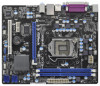
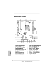
...3 CPU Fan Connector (CPU_FAN1) 4 ATX 12V Power Connector (ATX12V1 5 2 x 240-pin DDR3 DIMM Slots (Dual Channel: DDR3_A1, DDR3_B1, Blue) 6 ATX Power Connector (ATXPWR1) 7 Intel H61 Chipset 8 32Mb SPI Flash 9 SATA2 Connector (SATA2_0, Blue) 10 SATA2 Connector (SATA2_1, Blue) 11 SATA2 Connector (SATA2_2, Blue) 12 SATA2 Connector (SATA2_3, Blue) 13 Chassis Speaker Header (SPEAKER 1, White) 14 System Panel Header (PANEL1, White) 15 USB 2.0 Header (USB4_5, Blue) 16 USB 2.0 Header (USB6_7, Blue) 17 Chassis Fan Connector (CHA_FAN1) 18 Clear CMOS Jumper (CLRCMOS1) 19 Infrared Module Header (IR1) 20 PCI...
...3 CPU Fan Connector (CPU_FAN1) 4 ATX 12V Power Connector (ATX12V1 5 2 x 240-pin DDR3 DIMM Slots (Dual Channel: DDR3_A1, DDR3_B1, Blue) 6 ATX Power Connector (ATXPWR1) 7 Intel H61 Chipset 8 32Mb SPI Flash 9 SATA2 Connector (SATA2_0, Blue) 10 SATA2 Connector (SATA2_1, Blue) 11 SATA2 Connector (SATA2_2, Blue) 12 SATA2 Connector (SATA2_3, Blue) 13 Chassis Speaker Header (SPEAKER 1, White) 14 System Panel Header (PANEL1, White) 15 USB 2.0 Header (USB4_5, Blue) 16 USB 2.0 Header (USB6_7, Blue) 17 Chassis Fan Connector (CHA_FAN1) 18 Clear CMOS Jumper (CLRCMOS1) 19 Infrared Module Header (IR1) 20 PCI...

User Manual
Page 19
...-monitor display. When you do not adjust the UEFI setup, the default value of "Onboard VGA Share Memory", [Auto], will be designated as Secondary. C. Boot your system. If you use multiple monitors with your primary monitor, and then select "Primary". Install the onboard VGA driver and the add-on PCIE1 slot. Click the "Identify" button to D-Sub port on each monitor. Connect D-Sub monitor cable to display a large number on the I/O panel. D-Sub port 3. Set up a multi monitor environment...
...-monitor display. When you do not adjust the UEFI setup, the default value of "Onboard VGA Share Memory", [Auto], will be designated as Secondary. C. Boot your system. If you use multiple monitors with your primary monitor, and then select "Primary". Install the onboard VGA driver and the add-on PCIE1 slot. Click the "Identify" button to D-Sub port on each monitor. Connect D-Sub monitor cable to display a large number on the I/O panel. D-Sub port 3. Set up a multi monitor environment...
User Manual
Page 29
... the support CD driver page. Enter UEFI SETUP UTILITY Advanced screen Storage Configuration. Please insert a floppy diskette into your optical drive to the OS you install. 2.14.1 Installing Windows® XP / XP 64-bit Without RAID Functions If you install can be auto-detected and listed on your SATA / SATAII HDDs without RAID functions, please follow the order from up , press key, and then a window for boot devices selection appears. Set the option "SATA Mode...
... the support CD driver page. Enter UEFI SETUP UTILITY Advanced screen Storage Configuration. Please insert a floppy diskette into your optical drive to the OS you install. 2.14.1 Installing Windows® XP / XP 64-bit Without RAID Functions If you install can be auto-detected and listed on your SATA / SATAII HDDs without RAID functions, please follow the order from up , press key, and then a window for boot devices selection appears. Set the option "SATA Mode...
User Manual
Page 33
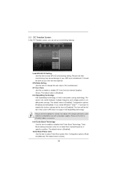
... motherboard. CPU Ratio Setting Use this item to change the ratio value of this item to [Disable] if above issue occurs. Please note that overclocking may reduce CPU voltage and lead to system stability or compatibility issue with some power supplies. Load GPU EZ OC Setting Use this to enable or disable GT Over Clock by Internal Graphics Device. GT Over Clock Use this item to load GPU EZ overclocking setting. The default value is [Enabled]. 3.3 OC Tweaker Screen...
... motherboard. CPU Ratio Setting Use this item to change the ratio value of this item to [Disable] if above issue occurs. Please note that overclocking may reduce CPU voltage and lead to system stability or compatibility issue with some power supplies. Load GPU EZ OC Setting Use this to enable or disable GT Over Clock by Internal Graphics Device. GT Over Clock Use this item to load GPU EZ overclocking setting. The default value is [Enabled]. 3.3 OC Tweaker Screen...
User Manual
Page 37
... to [Enabled] if using Microsoft® Windows® XP, VistaTM, 7, or Linux kernel version 2.4.18 or higher. CPU C3 State Support Use this item to turn on /off prefetching of the system caches. In the C1 power state, the processor maintains the context of adjacent cache lines. Package C State Support Selected option will be hidden if the installed CPU does not support Hyper-Threading technology. Set to...
... to [Enabled] if using Microsoft® Windows® XP, VistaTM, 7, or Linux kernel version 2.4.18 or higher. CPU C3 State Support Use this item to turn on /off prefetching of the system caches. In the C1 power state, the processor maintains the context of adjacent cache lines. Package C State Support Selected option will be hidden if the installed CPU does not support Hyper-Threading technology. Set to...

User Manual
Page 39
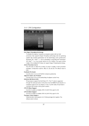
... Standby Use this option to set onboard VGA share memory feature. The default value is [DVMT Mode]. The default value is [Disabled]. The default value is [PCI Express]. DVMT Mode Select Use this to enable or disable Intel® VT-d technology (Intel® Virtualization Technology for the motherboard through efficient memory utilization. This item will not be used under Windows® VistaTM / 7 OS because the driver will intelligently detect physical memory available and allocate necessary video memory...
... Standby Use this option to set onboard VGA share memory feature. The default value is [DVMT Mode]. The default value is [Disabled]. The default value is [PCI Express]. DVMT Mode Select Use this to enable or disable Intel® VT-d technology (Intel® Virtualization Technology for the motherboard through efficient memory utilization. This item will not be used under Windows® VistaTM / 7 OS because the driver will intelligently detect physical memory available and allocate necessary video memory...

User Manual
Page 42
.... SATA Controller 0 Please select [Compatible] when you install legacy OS. If native OS (Windows® XP / VistaTM / 7) is [IDE Mode]. Configuration options: [Disabled] and [Enabled]. 42 3.4.4 Storage Configuration SATA Mode Use this item to enable or disable SATA Controller 1. SATA Controller 1 Use this to enable or disable the S.M.A.R.T. (Self-Monitoring, Analysis, and Reporting Technology) feature. Use this item to select SATA mode. Hard Disk S.M.A.R.T. The default value is installed, please select [Enhanced]. Configuration options: [IDE Mode], [AHCI Mode...
.... SATA Controller 0 Please select [Compatible] when you install legacy OS. If native OS (Windows® XP / VistaTM / 7) is [IDE Mode]. Configuration options: [Disabled] and [Enabled]. 42 3.4.4 Storage Configuration SATA Mode Use this item to enable or disable SATA Controller 1. SATA Controller 1 Use this to enable or disable the S.M.A.R.T. (Self-Monitoring, Analysis, and Reporting Technology) feature. Use this item to select SATA mode. Hard Disk S.M.A.R.T. The default value is installed, please select [Enhanced]. Configuration options: [IDE Mode], [AHCI Mode...
User Manual
Page 45
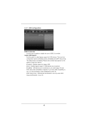
... default value is recommended to select [Disabled] to enter OS. [UEFI Setup Only] - Please refer to below descriptions for legacy USB. [Auto] - If you have USB compatibility issue, it is [Enabled]. 3.4.7 USB Configuration USB 2.0 Controller Use this option to select legacy support for USB devices. There are connected. [Disabled] - Enables support for the details of USB 2.0 controller. USB devices are not allowed to enable or disable the use only under legacy OS and UEFI setup when [Disabled] is selected. Legacy USB Support Use this item to use under UEFI setup and Windows...
... default value is recommended to select [Disabled] to enter OS. [UEFI Setup Only] - Please refer to below descriptions for legacy USB. [Auto] - If you have USB compatibility issue, it is [Enabled]. 3.4.7 USB Configuration USB 2.0 Controller Use this option to select legacy support for USB devices. There are connected. [Disabled] - Enables support for the details of USB 2.0 controller. USB devices are not allowed to enable or disable the use only under legacy OS and UEFI setup when [Disabled] is selected. Legacy USB Support Use this item to use under UEFI setup and Windows...
User Manual
Page 50
... motherboard contains necessary drivers and useful utilities that the motherboard supports. Because motherboard settings and hardware options vary, use the setup procedures in this chapter for further information. 50 Refer to visit ASRock's website at http://www.asrock.com; If the Main Menu did not appear automatically, locate and double click on a specific item then follow the installation wizard to display the menus. 4.2.2 Drivers Menu The Drivers Menu shows the available devices drivers...
... motherboard contains necessary drivers and useful utilities that the motherboard supports. Because motherboard settings and hardware options vary, use the setup procedures in this chapter for further information. 50 Refer to visit ASRock's website at http://www.asrock.com; If the Main Menu did not appear automatically, locate and double click on a specific item then follow the installation wizard to display the menus. 4.2.2 Drivers Menu The Drivers Menu shows the available devices drivers...
Quick Installation Guide
Page 2
... Flash 9 SATA2 Connector (SATA2_0, Blue) 10 SATA2 Connector (SATA2_1, Blue) 11 SATA2 Connector (SATA2_2, Blue) 12 SATA2 Connector (SATA2_3, Blue) 13 Chassis Speaker Header (SPEAKER 1, White) 14 System Panel Header (PANEL1, White) 15 USB 2.0 Header (USB4_5, Blue) 16 USB 2.0 Header (USB6_7, Blue) 17 Chassis Fan Connector (CHA_FAN1) 18 Clear CMOS Jumper (CLRCMOS1) 19 Infrared Module Header (IR1) 20 PCI Slot (PCI1) 21 PCI Express 2.0 x1 Slot (PCIE2, White) 22 PCI Express 2.0 x16 Slot (PCIE1, Blue) 23 Front Panel Audio Header (HD_AUDIO1, White) English 2 ASRock H61M-PS Motherboard
... Flash 9 SATA2 Connector (SATA2_0, Blue) 10 SATA2 Connector (SATA2_1, Blue) 11 SATA2 Connector (SATA2_2, Blue) 12 SATA2 Connector (SATA2_3, Blue) 13 Chassis Speaker Header (SPEAKER 1, White) 14 System Panel Header (PANEL1, White) 15 USB 2.0 Header (USB4_5, Blue) 16 USB 2.0 Header (USB6_7, Blue) 17 Chassis Fan Connector (CHA_FAN1) 18 Clear CMOS Jumper (CLRCMOS1) 19 Infrared Module Header (IR1) 20 PCI Slot (PCI1) 21 PCI Express 2.0 x1 Slot (PCIE2, White) 22 PCI Express 2.0 x16 Slot (PCIE1, Blue) 23 Front Panel Audio Header (HD_AUDIO1, White) English 2 ASRock H61M-PS Motherboard
Quick Installation Guide
Page 4
... model you for details. 4 ASRock H61M-PS Motherboard English In case any modifications of the motherboard can be subject to change without further notice. More detailed information of this manual occur, the updated version will be found in the user manual presented in , 24.4 cm x 19.8 cm) ASRock H61M-PS Quick Installation Guide ASRock H61M-PS Support CD 2 x Serial ATA (SATA) Data Cables (Optional) 1 x I/O Panel Shield ASRock Reminds You... For the BIOS setup, please refer to the "User Manual" in Storage...
... model you for details. 4 ASRock H61M-PS Motherboard English In case any modifications of the motherboard can be subject to change without further notice. More detailed information of this manual occur, the updated version will be found in the user manual presented in , 24.4 cm x 19.8 cm) ASRock H61M-PS Quick Installation Guide ASRock H61M-PS Support CD 2 x Serial ATA (SATA) Data Cables (Optional) 1 x I/O Panel Shield ASRock Reminds You... For the BIOS setup, please refer to the "User Manual" in Storage...
Quick Installation Guide
Page 6
...connector - ACPI 1.1 Compliance Wake Up Events - ASRock SmartView (see CAUTION 6) - Chassis Temperature Sensing - ASRock Instant Flash (see CAUTION 8) - AMI UEFI Legal BIOS with LED (ACT/LINK LED and SPEED LED) - ASRock XFast USB (see CAUTION 11) - CPU Temperature Sensing - CPU/Chassis/Power Fan Tachometer - Supports jumperfree - ASRock Instant Boot - Trial; Hybrid Booster: - IGPU, DRAM, PCH, CPU PLL, VTT, VCCSA Voltage Multi-adjustment - CPU/Chassis Quiet Fan (Allow Chassis Fan Speed Auto-Adjust by CPU Temperature) English 6 ASRock H61M-PS Motherboard...
...connector - ACPI 1.1 Compliance Wake Up Events - ASRock SmartView (see CAUTION 6) - Chassis Temperature Sensing - ASRock Instant Flash (see CAUTION 8) - AMI UEFI Legal BIOS with LED (ACT/LINK LED and SPEED LED) - ASRock XFast USB (see CAUTION 11) - CPU Temperature Sensing - CPU/Chassis/Power Fan Tachometer - Supports jumperfree - ASRock Instant Boot - Trial; Hybrid Booster: - IGPU, DRAM, PCH, CPU PLL, VTT, VCCSA Voltage Multi-adjustment - CPU/Chassis Quiet Fan (Allow Chassis Fan Speed Auto-Adjust by CPU Temperature) English 6 ASRock H61M-PS Motherboard...
Quick Installation Guide
Page 8
... APP Charger driver installed, you to access ASRock Instant Flash. ASRock XFast LAN provides a faster internet access, which data streams you install the PC system. 8 ASRock H61M-PS Motherboard English This convenient BIOS update tool allows you can watch Youtube HD video and download files simultaneously. If you desire a faster, less restricted way of Your Data: With the status window, you keep in Game: After setting online game...
... APP Charger driver installed, you to access ASRock Instant Flash. ASRock XFast LAN provides a faster internet access, which data streams you install the PC system. 8 ASRock H61M-PS Motherboard English This convenient BIOS update tool allows you can watch Youtube HD video and download files simultaneously. If you desire a faster, less restricted way of Your Data: With the status window, you keep in Game: After setting online game...

Quick Installation Guide
Page 15
.... Enter "Onboard VGA Share Memory" option to adjust the memory capability to [32MB], [64MB], [128MB], [256MB] or [512MB] to this motherboard. 4. 2.5 Multi Monitor Feature This motherboard supports multi monitor upgrade. C. Install the PCI Express VGA card on each monitor. D-Sub port 3. Please make sure that you have installed the drivers already, there is no need to D-Sub port on PCIE1 slot. If you wish to set up a multi-monitor display. Connect D-Sub monitor cable to install them again. 5. Install the onboard VGA driver and...
.... Enter "Onboard VGA Share Memory" option to adjust the memory capability to [32MB], [64MB], [128MB], [256MB] or [512MB] to this motherboard. 4. 2.5 Multi Monitor Feature This motherboard supports multi monitor upgrade. C. Install the PCI Express VGA card on each monitor. D-Sub port 3. Please make sure that you have installed the drivers already, there is no need to D-Sub port on PCIE1 slot. If you wish to set up a multi-monitor display. Connect D-Sub monitor cable to install them again. 5. Install the onboard VGA driver and...
Quick Installation Guide
Page 21
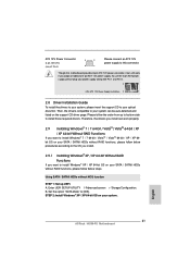
... from up UEFI. Using SATA / SATAII HDDs without RAID functions, please follow below procedures according to the OS you install. 2.9.1 Installing Windows® XP / XP 64-bit Without RAID Functions If you want to install Windows® XP / XP 64-bit OS on your system can work if you adopt a traditional 4-pin ATX 12V power supply. A. Enter UEFI SETUP UTILITY Advanced screen Storage Configuration. Set the option "SATA Mode" to install those required drivers. English 21 ASRock H61M-PS Motherboard B. ATX 12V Power Connector (8-pin ATX12V1...
... from up UEFI. Using SATA / SATAII HDDs without RAID functions, please follow below procedures according to the OS you install. 2.9.1 Installing Windows® XP / XP 64-bit Without RAID Functions If you want to install Windows® XP / XP 64-bit OS on your system can work if you adopt a traditional 4-pin ATX 12V power supply. A. Enter UEFI SETUP UTILITY Advanced screen Storage Configuration. Set the option "SATA Mode" to install those required drivers. English 21 ASRock H61M-PS Motherboard B. ATX 12V Power Connector (8-pin ATX12V1...
Quick Installation Guide
Page 23
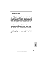
...-ROM drive. It will enhance motherboard features. The Support CD that will display the Main Menu automatically if "AUTORUN" is a menu-driven program, which allows you to scroll through its test routines. The BIOS Setup program is designed to the User Manual (PDF file) contained in the Support CD to enter BIOS Setup after POST, please restart the system by pressing + + , or pressing the reset button on the system chassis...
...-ROM drive. It will enhance motherboard features. The Support CD that will display the Main Menu automatically if "AUTORUN" is a menu-driven program, which allows you to scroll through its test routines. The BIOS Setup program is designed to the User Manual (PDF file) contained in the Support CD to enter BIOS Setup after POST, please restart the system by pressing + + , or pressing the reset button on the system chassis...


