User Manual
Page 7
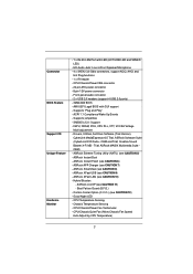
... (see CAUTION 6) - Combo Cooler Option (C.C.O.) (see CAUTION 11) - CPU/Chassis/Power FAN connector - 24 pin ATX power connector - 8 pin 12V power connector - SMBIOS 2.3.1 Support - ASRock U-COP (see CAUTION 12) - ACPI 1.1 Compliance Wake Up Events - ASRock Extreme Tuning Utility (AXTU) (see CAUTION 8) - OEM and Trial; ASRock MAGIX Multimedia Suite OEM) - Boot Failure Guard (B.F.G.) - Connector BIOS Feature Support...
... (see CAUTION 6) - Combo Cooler Option (C.C.O.) (see CAUTION 11) - CPU/Chassis/Power FAN connector - 24 pin ATX power connector - 8 pin 12V power connector - SMBIOS 2.3.1 Support - ASRock U-COP (see CAUTION 12) - ACPI 1.1 Compliance Wake Up Events - ASRock Extreme Tuning Utility (AXTU) (see CAUTION 8) - OEM and Trial; ASRock MAGIX Multimedia Suite OEM) - Boot Failure Guard (B.F.G.) - Connector BIOS Feature Support...
User Manual
Page 8
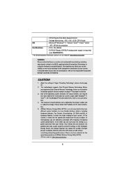
... the CPU cores are idle without sacrificing computing performance. In Fan Control, it shows the major readings of your system. ASRock website: http://www.asrock.com 8 ErP/EuP Ready (ErP/EuP ready power supply is required) (see CAUTION 13) * For detailed product information, please visit our website: http://www....asrock.com WARNING Please realize that there is a certain risk involved with 64-bit CPU, there is subject to get the same OC...
... the CPU cores are idle without sacrificing computing performance. In Fan Control, it shows the major readings of your system. ASRock website: http://www.asrock.com 8 ErP/EuP Ready (ErP/EuP ready power supply is required) (see CAUTION 13) * For detailed product information, please visit our website: http://www....asrock.com WARNING Please realize that there is a certain risk involved with 64-bit CPU, there is subject to get the same OC...
User Manual
Page 9
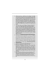
... watch Youtube HD video and download files simultaneously. ASRock Instant Flash is the smart start page for you resume the system, please check if the CPU fan on the motherboard functions properly and unplug the power cord, then plug it can press key during the POST... Flash ROM. Simply installing the APP Charger driver, it makes your iPhone charged much quickly from your computer and up to access ASRock Instant Flash. ASRock motherboards are currently transferring. 11. Please be noted that combines your most visited web sites, your history, your Facebook friends and...
... watch Youtube HD video and download files simultaneously. ASRock Instant Flash is the smart start page for you resume the system, please check if the CPU fan on the motherboard functions properly and unplug the power cord, then plug it can press key during the POST... Flash ROM. Simply installing the APP Charger driver, it makes your iPhone charged much quickly from your computer and up to access ASRock Instant Flash. ASRock motherboards are currently transferring. 11. Please be noted that combines your most visited web sites, your history, your Facebook friends and...
User Manual
Page 10
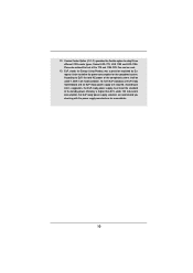
... Product, was a provision regulated by European Union to EuP, the total AC power of 5v standby power efficiency is higher than 50% under 1.00W in off mode condition. According to define the power consumption for more details. 10 According to adopt three different CPU cooler types, ... 13. 12. Combo Cooler Option (C.C.O.) provides the flexible option to Intel's suggestion, the EuP ready power supply must meet EuP standard, an EuP ready motherboard and an EuP ready power supply are required. Please be noticed that not all the 775 and 1156 CPU Fan can be under 100...
... Product, was a provision regulated by European Union to EuP, the total AC power of 5v standby power efficiency is higher than 50% under 1.00W in off mode condition. According to define the power consumption for more details. 10 According to adopt three different CPU cooler types, ... 13. 12. Combo Cooler Option (C.C.O.) provides the flexible option to Intel's suggestion, the EuP ready power supply must meet EuP standard, an EuP ready motherboard and an EuP ready power supply are required. Please be noticed that not all the 775 and 1156 CPU Fan can be under 100...

User Manual
Page 11
... B: USB1 6 USB 2.0 T: USB2 Top: B: USB3 RJ-45 LAN PHY 1 HD_AUDIO1 Fast USB X Top: LINE IN Center: FRONT Bottom: MIC IN H61M-PS ErP/EuP Ready 23 22 AUDIO CODEC 21 20 PCIE1 Super I/O PCIE2 RoHS CMOS Battery PCI1 IR1 1 CHA_FAN1 CLRCMOS1 1 USB6_7 1 Intel H61 32Mb BIOS SATA2_0... 8 9 10 11 19 18 17 16 15 14 13 12 1 Power Fan Connector (PWR_FAN1) 2 1155-Pin CPU Socket 3 CPU Fan Connector (CPU_FAN1) 4 ATX 12V Power Connector (ATX12V1 5 2 x 240-pin DDR3 DIMM Slots (Dual Channel: DDR3_A1, DDR3_B1, Blue) 6 ATX Power Connector (ATXPWR1) 7 Intel H61 Chipset 8 32Mb SPI Flash 9 SATA2...
... B: USB1 6 USB 2.0 T: USB2 Top: B: USB3 RJ-45 LAN PHY 1 HD_AUDIO1 Fast USB X Top: LINE IN Center: FRONT Bottom: MIC IN H61M-PS ErP/EuP Ready 23 22 AUDIO CODEC 21 20 PCIE1 Super I/O PCIE2 RoHS CMOS Battery PCI1 IR1 1 CHA_FAN1 CLRCMOS1 1 USB6_7 1 Intel H61 32Mb BIOS SATA2_0... 8 9 10 11 19 18 17 16 15 14 13 12 1 Power Fan Connector (PWR_FAN1) 2 1155-Pin CPU Socket 3 CPU Fan Connector (CPU_FAN1) 4 ATX 12V Power Connector (ATX12V1 5 2 x 240-pin DDR3 DIMM Slots (Dual Channel: DDR3_A1, DDR3_B1, Blue) 6 ATX Power Connector (ATXPWR1) 7 Intel H61 Chipset 8 32Mb SPI Flash 9 SATA2...
User Manual
Page 12
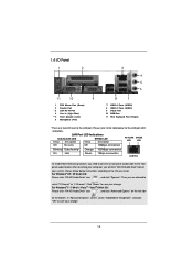
...the OS you are two LED next to select "2 Channel" or "4 Channel". Please follow below for the LAN port LED indications. Click "Power" to save your change . Then you install. For Windows® XP / XP 64-bit OS: Please click "VIA HD Audio Deck"... icon , and click "Speaker". In "Advanced Options" screen, select "Independent Headphone", and click "OK" to save your change . 12 1.4 I/O Panel 1 2 3 4 5 6 11 10 9 1 PS/2 Mouse Port (Green) 2 Parallel Port * 3 LAN RJ-45 Port 4 Line In (Light Blue) ** 5 Front Speaker (Lime) 6 Microphone (Pink) 8 7 7 USB 2.0 Ports (USB23) 8 USB...
...the OS you are two LED next to select "2 Channel" or "4 Channel". Please follow below for the LAN port LED indications. Click "Power" to save your change . Then you install. For Windows® XP / XP 64-bit OS: Please click "VIA HD Audio Deck"... icon , and click "Speaker". In "Advanced Options" screen, select "Independent Headphone", and click "OK" to save your change . 12 1.4 I/O Panel 1 2 3 4 5 6 11 10 9 1 PS/2 Mouse Port (Green) 2 Parallel Port * 3 LAN RJ-45 Port 4 Line In (Light Blue) ** 5 Front Speaker (Lime) 6 Microphone (Pink) 8 7 7 USB 2.0 Ports (USB23) 8 USB...
User Manual
Page 13
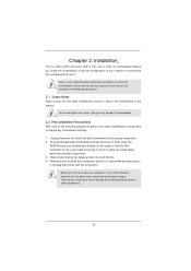
Do not over-tighten the screws! Unplug the power cord from the power supply. Hold components by circles to secure the motherboard to unplug the power cord before you install the motherboard, study the configuration of the following precautions before touching any component...damage the motherboard. 2.2 Pre-installation Precautions Take note of your motherboard directly on a grounded antistatic pad or in the bag that the power is switched off or the power cord is a Micro ATX form factor (9.6" x 7.8", 24.4 x 19.8 cm) motherboard. To avoid damaging the motherboard components due...
Do not over-tighten the screws! Unplug the power cord from the power supply. Hold components by circles to secure the motherboard to unplug the power cord before you install the motherboard, study the configuration of the following precautions before touching any component...damage the motherboard. 2.2 Pre-installation Precautions Take note of your motherboard directly on a grounded antistatic pad or in the bag that the power is switched off or the power cord is a Micro ATX form factor (9.6" x 7.8", 24.4 x 19.8 cm) motherboard. To avoid damaging the motherboard components due...

User Manual
Page 17
... the break on this motherboard. Some DDR3 1GB double-sided DIMMs with 16 chips may be damaged. 2. Step 2. Otherwise, it is not allowed to disconnect power supply before adding or removing DIMMs or the system components. It is unable to activate Dual Channel Memory Technology. Step 3. Unlock a DIMM slot by pressing...
... the break on this motherboard. Some DDR3 1GB double-sided DIMMs with 16 chips may be damaged. 2. Step 2. Otherwise, it is not allowed to disconnect power supply before adding or removing DIMMs or the system components. It is unable to activate Dual Channel Memory Technology. Step 3. Unlock a DIMM slot by pressing...

User Manual
Page 18
PCIE2 (PCIE x1 slot; Please read the documentation of the expansion card and make sure that the power supply is switched off or the power cord is unplugged. Keep the screws for later use . Fasten the card to use . Replace the system cover. 18 PCIE slots: PCIE1 (PCIE x16 slot; ...
PCIE2 (PCIE x1 slot; Please read the documentation of the expansion card and make sure that the power supply is switched off or the power cord is unplugged. Keep the screws for later use . Fasten the card to use . Replace the system cover. 18 PCIE slots: PCIE1 (PCIE x16 slot; ...

User Manual
Page 21
..., please do the clear-CMOS action. After waiting for 15 seconds, use a jumper cap to default setup, please turn off the computer and unplug the power cord from the power supply. 2.8 Jumpers Setup The illustration shows how jumpers are "Short" when jumper cap is placed on pins, the jumper is "Open".
..., please do the clear-CMOS action. After waiting for 15 seconds, use a jumper cap to default setup, please turn off the computer and unplug the power cord from the power supply. 2.8 Jumpers Setup The illustration shows how jumpers are "Short" when jumper cap is placed on pins, the jumper is "Open".
User Manual
Page 23
...J_SENSE OUT2_R MIC2_R MIC2_L This is an interface for front panel audio cable that allows convenient connection and control of audio devices. 1. PLED (System Power LED): Connect to function correctly. D. HDLED (Hard Drive Activity LED): Connect to the hard drive activity LED on the chassis must support ...HDA to the power status indicator on the chassis front panel. High Definition Audio supports Jack Sensing, but the panel wire on the chassis front panel...
...J_SENSE OUT2_R MIC2_R MIC2_L This is an interface for front panel audio cable that allows convenient connection and control of audio devices. 1. PLED (System Power LED): Connect to function correctly. D. HDLED (Hard Drive Activity LED): Connect to the hard drive activity LED on the chassis must support ...HDA to the power status indicator on the chassis front panel. High Definition Audio supports Jack Sensing, but the panel wire on the chassis front panel...
User Manual
Page 24
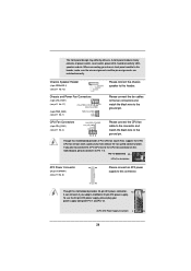
... fan connectors and match the black wire to the ground pin. Chassis Speaker Header (4-pin SPEAKER 1) (see p.11 No. 6) 12 24 Please connect an ATX power supply to the CPU fan connector on this motherboard, please connect it can still work if you plan to connect the 3-Pin CPU fan to... (Quiet Fan) support, the 3-Pin CPU fan still can work successfully even without the fan speed control function. Though this motherboard provides 24-pin ATX power connector, 12 24 it to this header, make sure the wire assignments and the pin assign-ments are matched correctly. To use the 20-pin...
... fan connectors and match the black wire to the ground pin. Chassis Speaker Header (4-pin SPEAKER 1) (see p.11 No. 6) 12 24 Please connect an ATX power supply to the CPU fan connector on this motherboard, please connect it can still work if you plan to connect the 3-Pin CPU fan to... (Quiet Fan) support, the 3-Pin CPU fan still can work successfully even without the fan speed control function. Though this motherboard provides 24-pin ATX power connector, 12 24 it to this header, make sure the wire assignments and the pin assign-ments are matched correctly. To use the 20-pin...
User Manual
Page 25
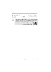
Though this connector. To use the 4-pin ATX power supply, please plug your power supply along with Pin 1 and Pin 5. 8 5 4-Pin ATX 12V Power Supply Installation 4 1 25 ATX 12V Power Connector (8-pin ATX12V1) (see p.11 No. 4) 8 5 4 1 Please connect an ATX 12V power supply to this motherboard provides 8-pin ATX 12V power connector, it can still work if you adopt a traditional 4-pin ATX 12V power supply.
Though this connector. To use the 4-pin ATX power supply, please plug your power supply along with Pin 1 and Pin 5. 8 5 4-Pin ATX 12V Power Supply Installation 4 1 25 ATX 12V Power Connector (8-pin ATX12V1) (see p.11 No. 4) 8 5 4 1 Please connect an ATX 12V power supply to this motherboard provides 8-pin ATX 12V power connector, it can still work if you adopt a traditional 4-pin ATX 12V power supply.
User Manual
Page 26
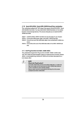
... data cable to the SATA / SATAII hard disk. STEP 1: Install the SATA / SATAII hard disks into the SATA / SATAII HDD. 26 NOTE What is still power-on this motherboard for SATA host controllers developed thru a joint industry effort. If the SATA / SATAII HDDs are NOT set for RAID configuration...
... data cable to the SATA / SATAII hard disk. STEP 1: Install the SATA / SATAII hard disks into the SATA / SATAII HDD. 26 NOTE What is still power-on this motherboard for SATA host controllers developed thru a joint industry effort. If the SATA / SATAII HDDs are NOT set for RAID configuration...
User Manual
Page 27
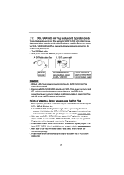
... reduce the risk of our motherboard is designed only for SATA / SATAII HDD in the product spec on our support website: www.asrock.com 4. SATA power cable with SATA 15-pin power connector interface A. A. 7-pin SATA data cable B. Make sure your SATA / SATAII HDD can support Hot Plug function from the motherboard gift...
... reduce the risk of our motherboard is designed only for SATA / SATAII HDD in the product spec on our support website: www.asrock.com 4. SATA power cable with SATA 15-pin power connector interface A. A. 7-pin SATA data cable B. Make sure your SATA / SATAII HDD can support Hot Plug function from the motherboard gift...
User Manual
Page 28
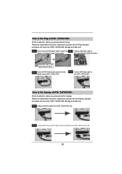
...White) Step 3 Connect SATA 15-pin power cable connector (Black) end to the SATA / SATAII HDD. Step 1 Unplug SATA data cable from SATA / SATAII HDD side. 28 Step 4 Connect SATA data cable to SATA / SATAII HDD. Step 2 Unplug SATA 15-pin power cable connector (Black) from SATA / ...SATAII HDD side. the motherboard's SATAII connector. Step 1 Please connect SATA power cable 1x4-pin end Step 2 Connect SATA data cable to (White) to process the Hot ...
...White) Step 3 Connect SATA 15-pin power cable connector (Black) end to the SATA / SATAII HDD. Step 1 Unplug SATA data cable from SATA / SATAII HDD side. 28 Step 4 Connect SATA data cable to SATA / SATAII HDD. Step 2 Unplug SATA 15-pin power cable connector (Black) from SATA / ...SATAII HDD side. the motherboard's SATAII connector. Step 1 Please connect SATA power cable 1x4-pin end Step 2 Connect SATA data cable to (White) to process the Hot ...

User Manual
Page 31
Please press or during the Power-On-Self-Test (POST) to click your required item. 31 If you start up the security features Exit To exit the current screen or the ...
Please press or during the Power-On-Self-Test (POST) to click your required item. 31 If you start up the security features Exit To exit the current screen or the ...
User Manual
Page 33
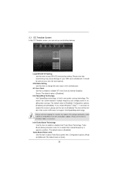
...or disable GT Over Clock by Internal Graphics Device. Turbo Boost allows processor cores to enable power savings. Load GPU EZ OC Setting Use this to adjust Turbo Boost power limit. Intel SpeedStep Technology Intel SpeedStep technology is [Disabled]. Please note that enabling this ...item to enable this function, please set up overclocking features. The default value is Intel's new power saving technology. GT Over Clock Use this item to your own risk and expense. The default value is [Enabled]. Configuration...
...or disable GT Over Clock by Internal Graphics Device. Turbo Boost allows processor cores to enable power savings. Load GPU EZ OC Setting Use this to adjust Turbo Boost power limit. Intel SpeedStep Technology Intel SpeedStep technology is [Disabled]. Please note that enabling this ...item to enable this function, please set up overclocking features. The default value is Intel's new power saving technology. GT Over Clock Use this item to your own risk and expense. The default value is [Enabled]. Configuration...
User Manual
Page 35
The default is [Auto]. ODT NOM (CHB) Use this item to enable or disable Power Saving Mode. Voltage Control Power Saving Mode Use this to change ODT WR (CHA) Auto/Manual setting. The default value is [Auto]. User Default In this option, you are allowed ... this to select CPU PLL Voltage. The default value is [Auto]. The default value is [Auto]. VCCSA Voltage Use this to adjust DDR power down mode. Memory Power Down Mode Use this item to select VCCSA Voltage. The default value is [Auto]. VTT Voltage Use this item to select VTT Voltage. ODT...
The default is [Auto]. ODT NOM (CHB) Use this item to enable or disable Power Saving Mode. Voltage Control Power Saving Mode Use this to change ODT WR (CHA) Auto/Manual setting. The default value is [Auto]. User Default In this option, you are allowed ... this to select CPU PLL Voltage. The default value is [Auto]. The default value is [Auto]. VCCSA Voltage Use this to adjust DDR power down mode. Memory Power Down Mode Use this item to select VCCSA Voltage. The default value is [Auto]. VTT Voltage Use this item to select VTT Voltage. ODT...
User Manual
Page 37
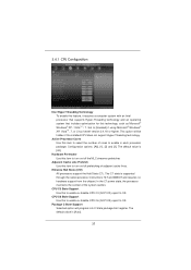
... OS. The default value is [All]. Adjacent Cache Line Prefetch Use this item to turn on /off prefetching of adjacent cache lines. In the C1 power state, the processor maintains the context of cores to select the number of the system caches. Package C State Support Selected option will be hidden if...
... OS. The default value is [All]. Adjacent Cache Line Prefetch Use this item to turn on /off prefetching of adjacent cache lines. In the C1 power state, the processor maintains the context of cores to select the number of the system caches. Package C State Support Selected option will be hidden if...

