User Manual
Page 3
... Motherboard Layout 13 1.5 I/O Panel 14 2 Installation 16 2.1 Screw Holes 16 2.2 Pre-installation Precautions 16 2.3 CPU Installation 17 2.4 Installation of Heatsink and CPU fan 19 2.5 Installation of Memory Modules (DIMM 20 2.6 Expansion Slots (PCI Express Slots 21 2.7 Jumpers Setup 22 2.8 Onboard Headers and Connectors 23 2.9 Driver Installation Guide 28 2.10 Installing Windows® 8 / 8 64-bit / 7 / 7 64-bit / VistaTM / VistaTM 64-bit / XP / XP 64-bit Without RAID Functions . 28 2.10.1 Installing Windows® XP / XP 64-bit Without RAID Functions 28 2.10.2 Installing Windows...
... Motherboard Layout 13 1.5 I/O Panel 14 2 Installation 16 2.1 Screw Holes 16 2.2 Pre-installation Precautions 16 2.3 CPU Installation 17 2.4 Installation of Heatsink and CPU fan 19 2.5 Installation of Memory Modules (DIMM 20 2.6 Expansion Slots (PCI Express Slots 21 2.7 Jumpers Setup 22 2.8 Onboard Headers and Connectors 23 2.9 Driver Installation Guide 28 2.10 Installing Windows® 8 / 8 64-bit / 7 / 7 64-bit / VistaTM / VistaTM 64-bit / XP / XP 64-bit Without RAID Functions . 28 2.10.1 Installing Windows® XP / XP 64-bit Without RAID Functions 28 2.10.2 Installing Windows...
User Manual
Page 4
... 3.1.1 UEFI Menu Bar 40 3.1.2 Navigation Keys 41 3.2 Main Screen 41 3.3 OC Tweaker Screen 42 3.4 Advanced Screen 46 3.4.1 CPU Configuration 47 3.4.2 North Bridge Configuration 49 3.4.3 South Bridge Configuration 50 3.4.4 Storage Configuration 51 3.4.5 Intel(R) Rapid Start Technology 52 3.4.6 Intel(R) Smart Connect Technology 53 3.4.7 Super IO Configuration 54 3.4.8 ACPI Configuration 55 3.4.9 USB Configuration 56 3.5 Tool 57 3.6 Hardware Health Event Monitoring Screen 59 3.7 Boot Screen 60 3.8 Security Screen 62 3.9 Exit Screen 63 4 Software Support 64 4.1 Install Operating...
... 3.1.1 UEFI Menu Bar 40 3.1.2 Navigation Keys 41 3.2 Main Screen 41 3.3 OC Tweaker Screen 42 3.4 Advanced Screen 46 3.4.1 CPU Configuration 47 3.4.2 North Bridge Configuration 49 3.4.3 South Bridge Configuration 50 3.4.4 Storage Configuration 51 3.4.5 Intel(R) Rapid Start Technology 52 3.4.6 Intel(R) Smart Connect Technology 53 3.4.7 Super IO Configuration 54 3.4.8 ACPI Configuration 55 3.4.9 USB Configuration 56 3.5 Tool 57 3.6 Hardware Health Event Monitoring Screen 59 3.7 Boot Screen 60 3.8 Security Screen 62 3.9 Exit Screen 63 4 Software Support 64 4.1 Install Operating...
User Manual
Page 5
... ASRock H61M-HP4 Motherboard (Micro ATX Form Factor) ASRock H61M-HP4 Quick Installation Guide ASRock H61M-HP4 Support CD 2 x Serial ATA (SATA) Data Cables (Optional) 1 x I/O Panel Shield ASRock Reminds You... In this manual, chapter 1 and 2 contain introduction of this manual will be subject to this manual occur, the updated version will be available on ASRock website as well. ASRock website http://www.asrock.com If you are using. To get better performance in Windows® 8 / 8 64-bit / 7 / 7 64-bit / VistaTM / VistaTM 64-bit...
... ASRock H61M-HP4 Motherboard (Micro ATX Form Factor) ASRock H61M-HP4 Quick Installation Guide ASRock H61M-HP4 Support CD 2 x Serial ATA (SATA) Data Cables (Optional) 1 x I/O Panel Shield ASRock Reminds You... In this manual, chapter 1 and 2 contain introduction of this manual will be subject to this manual occur, the updated version will be available on ASRock website as well. ASRock website http://www.asrock.com If you are using. To get better performance in Windows® 8 / 8 64-bit / 7 / 7 64-bit / VistaTM / VistaTM 64-bit...
User Manual
Page 6
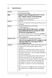
... CPU - Supports Intel® Rapid Start Technology and Smart Connect Technology - Dual Channel DDR3 Memory Technology - 2 x DDR3 DIMM slots - Supports Intel® HD Graphics Built-in LGA1155 Package - Intel® H61 - Max. All Solid Capacitor design - Supports Intel® Turbo Boost 2.0 Technology - Max. With Intel® Sandy Bridge CPU, it only supports PCIE 2.0. - 1 x PCI Express 2.0 x1 slot * Intel® HD Graphics Built-in Visuals: Intel® Quick Sync Video 2.0, Intel® InTruTM 3D, Intel® Clear Video HD Technology...
... CPU - Supports Intel® Rapid Start Technology and Smart Connect Technology - Dual Channel DDR3 Memory Technology - 2 x DDR3 DIMM slots - Supports Intel® HD Graphics Built-in LGA1155 Package - Intel® H61 - Max. All Solid Capacitor design - Supports Intel® Turbo Boost 2.0 Technology - Max. With Intel® Sandy Bridge CPU, it only supports PCIE 2.0. - 1 x PCI Express 2.0 x1 slot * Intel® HD Graphics Built-in Visuals: Intel® Quick Sync Video 2.0, Intel® InTruTM 3D, Intel® Clear Video HD Technology...
User Manual
Page 7
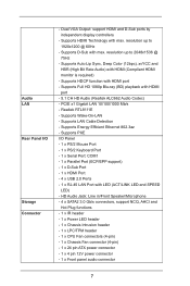
... Speaker/Microphone - 4 x SATA2 3.0 Gb/s connectors, support NCQ, AHCI and Hot Plug functions - 1 x IR header - 1 x Power LED header - 1 x Chassis Intrusion header - 1 x LPC/TPM header - 1 x CPU Fan connectors (4-pin) - 1 x Chassis Fan connector (4-pin) - 1 x 24 pin ATX power connector - 1 x 4 pin 12V power connector - 1 x Front panel audio connector 7 Dual VGA Output: support HDMI and D-Sub ports by independent display controllers - Supports LAN Cable Detection - Supports Energy Efficient Ethernet 802.3az - Audio LAN Rear Panel I /O Panel - 1 x PS/2 Mouse Port - 1 x PS/2 Keyboard...
... Speaker/Microphone - 4 x SATA2 3.0 Gb/s connectors, support NCQ, AHCI and Hot Plug functions - 1 x IR header - 1 x Power LED header - 1 x Chassis Intrusion header - 1 x LPC/TPM header - 1 x CPU Fan connectors (4-pin) - 1 x Chassis Fan connector (4-pin) - 1 x 24 pin ATX power connector - 1 x 4 pin 12V power connector - 1 x Front panel audio connector 7 Dual VGA Output: support HDMI and D-Sub ports by independent display controllers - Supports LAN Cable Detection - Supports Energy Efficient Ethernet 802.3az - Audio LAN Rear Panel I /O Panel - 1 x PS/2 Mouse Port - 1 x PS/2 Keyboard...
User Manual
Page 8
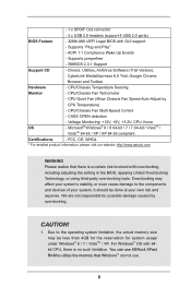
...connector - 2 x USB 2.0 headers (support 4 USB 2.0 ports) BIOS Feature - 32Mb AMI UEFI Legal BIOS with overclocking, including adjusting the setting in the BIOS, applying Untied Overclocking Technology, or using third-party overclocking tools. ACPI 1.1 Compliance Wake Up Events - Voltage Monitoring: +12V, +5V, +3.3V, CPU Vcore OS - It should be less than 4GB for the reservation for possible damage caused by CPU Temperature) - CPU Quiet Fan (Allow Chassis Fan Speed Auto-Adjust by overclocking. Microsoft® Windows® 8 / 8 64-bit / 7 / 7 64-bit / VistaTM / VistaTM 64-bit...
...connector - 2 x USB 2.0 headers (support 4 USB 2.0 ports) BIOS Feature - 32Mb AMI UEFI Legal BIOS with overclocking, including adjusting the setting in the BIOS, applying Untied Overclocking Technology, or using third-party overclocking tools. ACPI 1.1 Compliance Wake Up Events - Voltage Monitoring: +12V, +5V, +3.3V, CPU Vcore OS - It should be less than 4GB for the reservation for possible damage caused by CPU Temperature) - CPU Quiet Fan (Allow Chassis Fan Speed Auto-Adjust by overclocking. Microsoft® Windows® 8 / 8 64-bit / 7 / 7 64-bit / VistaTM / VistaTM 64-bit...
User Manual
Page 9
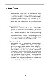
... leverages the S3 and S4 ACPI features which includes Hardware Monitor, Fan Control and XFast RAM. 1.3 Unique Features ASRock Extreme Tuning Utility (AXTU) ASRock Extreme Tuning Utility (AXTU) is a BIOS flash utility embedded in Flash ROM. ASRock Instant Boot ASRock Instant Boot allows you can update your Windows® desktop in a few clicks without entering operating systems first like MSDOS or Windows®. In Hardware Monitor, it shows the fan speed and temperature for your system. By...
... leverages the S3 and S4 ACPI features which includes Hardware Monitor, Fan Control and XFast RAM. 1.3 Unique Features ASRock Extreme Tuning Utility (AXTU) ASRock Extreme Tuning Utility (AXTU) is a BIOS flash utility embedded in Flash ROM. ASRock Instant Boot ASRock Instant Boot allows you can update your Windows® desktop in a few clicks without entering operating systems first like MSDOS or Windows®. In Hardware Monitor, it shows the fan speed and temperature for your system. By...
User Manual
Page 13
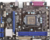
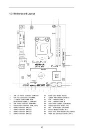
...1 ATX 12V Power Connector (ATX12V1) 2 CPU Fan Connector (CPU_FAN1) 3 2 x 240-pin DDR3 DIMM Slots (Dual Channel: DDR3_A1, DDR3_B1) 4 ATX Power Connector (ATXPWR1) 5 Chassis Fan Connector (CHA_FAN1) 6 SATA2 Connector (SATA_1) 7 SATA2 Connector (SATA_0) 8 SATA2 Connector (SATA_3) 9 SATA2 Connector (SATA_2) 10 Power LED Header (PLED1) 11 System Panel Header (PANEL1) 12 USB 2.0 Header (USB6_7) 13 USB 2.0 Header (USB4_5) 14 Clear CMOS Jumper (CLRCMOS1) 15 Chassis Intrusion Header (CI1) 16 LPC / TPM Header (LPC/TPM1) 17 Infrared Module Header (IR1) 18 Front Panel Audio Header (HD_AUDIO1) 19 SPDIF...
...1 ATX 12V Power Connector (ATX12V1) 2 CPU Fan Connector (CPU_FAN1) 3 2 x 240-pin DDR3 DIMM Slots (Dual Channel: DDR3_A1, DDR3_B1) 4 ATX Power Connector (ATXPWR1) 5 Chassis Fan Connector (CHA_FAN1) 6 SATA2 Connector (SATA_1) 7 SATA2 Connector (SATA_0) 8 SATA2 Connector (SATA_3) 9 SATA2 Connector (SATA_2) 10 Power LED Header (PLED1) 11 System Panel Header (PANEL1) 12 USB 2.0 Header (USB6_7) 13 USB 2.0 Header (USB4_5) 14 Clear CMOS Jumper (CLRCMOS1) 15 Chassis Intrusion Header (CI1) 16 LPC / TPM Header (LPC/TPM1) 17 Infrared Module Header (IR1) 18 Front Panel Audio Header (HD_AUDIO1) 19 SPDIF...
User Manual
Page 22
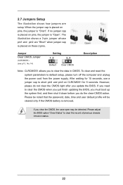
..., use a jumper cap to clear the CMOS when you just finish updating the BIOS, you must boot up the system first, and then shut it down before you clear the CMOS, the case open may be cleared only if the CMOS battery is removed. If you need to short pin2 and pin3 on pins, the jumper is "Open". Please be noted that the password, date, time and user default profile...
..., use a jumper cap to clear the CMOS when you just finish updating the BIOS, you must boot up the system first, and then shut it down before you clear the CMOS, the case open may be cleared only if the CMOS battery is removed. If you need to short pin2 and pin3 on pins, the jumper is "Open". Please be noted that the password, date, time and user default profile...
User Manual
Page 25
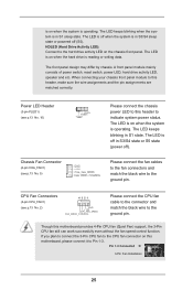
Pin 1-3 Connected 3-Pin Fan Installation 25 HDLED (Hard Drive Activity LED): Connect to the ground pin. A front panel module mainly consists of power switch, reset switch, power LED, hard drive activity LED, speaker and etc. The front panel design may differ by chassis. CPU Fan Connectors (4-pin CPU_FAN1) 4 3 2 1 (see p.13 No. 5) Please connect the chassis power LED to this motherboard, please connect it to the ground pin. Though this header, make sure the wire assignments and the pin assign-ments are matched correctly. The LED is off ...
Pin 1-3 Connected 3-Pin Fan Installation 25 HDLED (Hard Drive Activity LED): Connect to the ground pin. A front panel module mainly consists of power switch, reset switch, power LED, hard drive activity LED, speaker and etc. The front panel design may differ by chassis. CPU Fan Connectors (4-pin CPU_FAN1) 4 3 2 1 (see p.13 No. 5) Please connect the chassis power LED to this motherboard, please connect it to the ground pin. Though this header, make sure the wire assignments and the pin assign-ments are matched correctly. The LED is off ...
User Manual
Page 26
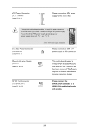
... connect an ATX 12V power supply to this connector. Chassis Intrusion Header (2-pin CI1) (see p.13, No. 15) SPDIF Out Connector (2-pin SPDIF_OUT1) (see p.13, No. 19) This motherboard supports CASE OPEN detection feature that detects if the chassis cover has been removed. This feature requires a chassis with Pin 1 and Pin 13. To use the 20-pin ATX power supply, please plug your power supply along with chassis intrusion detection design. Please connect the SPDIF_OUT connector of a HDMI VGA card to this header with a cable...
... connect an ATX 12V power supply to this connector. Chassis Intrusion Header (2-pin CI1) (see p.13, No. 15) SPDIF Out Connector (2-pin SPDIF_OUT1) (see p.13, No. 19) This motherboard supports CASE OPEN detection feature that detects if the chassis cover has been removed. This feature requires a chassis with Pin 1 and Pin 13. To use the 20-pin ATX power supply, please plug your power supply along with chassis intrusion detection design. Please connect the SPDIF_OUT connector of a HDMI VGA card to this header with a cable...
User Manual
Page 28
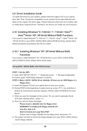
Set the option "SATA Mode Selection" to format and copy files [YN]? Insert the Support CD into the floppy drive. WARNING! Formatting the floppy diskette will start to install Windows® XP / XP 64-bit OS on the support CD driver page. 2.9 Driver Installation Guide To install the drivers to your system, please insert the support CD to your system. Enter UEFI SETUP UTILITY Advanced screen Storage Configuration. Start to [AHCI]. Using SATA / SATA2 HDDs with NCQ function STEP 1: Set Up UEFI. Please select CD-ROM as...
Set the option "SATA Mode Selection" to format and copy files [YN]? Insert the Support CD into the floppy drive. WARNING! Formatting the floppy diskette will start to install Windows® XP / XP 64-bit OS on the support CD driver page. 2.9 Driver Installation Guide To install the drivers to your system, please insert the support CD to your system. Enter UEFI SETUP UTILITY Advanced screen Storage Configuration. Start to [AHCI]. Using SATA / SATA2 HDDs with NCQ function STEP 1: Set Up UEFI. Please select CD-ROM as...
User Manual
Page 40
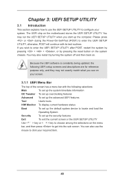
... screen or the UEFI SETUP UTILITY Use < > key or < > key to choose among the selections on the motherboard stores the UEFI SETUP UTILITY. Because the UEFI software is constantly being updated, the following selections: Main To set up the system time/date information OC Tweaker To set up overclocking features Advanced To set up the advanced UEFI features Tool Useful tools H/W Monitor To display current hardware status Boot To set up the default system device to locate and load...
... screen or the UEFI SETUP UTILITY Use < > key or < > key to choose among the selections on the motherboard stores the UEFI SETUP UTILITY. Because the UEFI software is constantly being updated, the following selections: Main To set up the system time/date information OC Tweaker To set up overclocking features Advanced To set up the advanced UEFI features Tool Useful tools H/W Monitor To display current hardware status Boot To set up the default system device to locate and load...
User Manual
Page 47
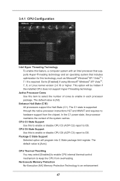
... [Enabled] to enable CPU internal thermal control mechanism to OS. The default value is an enhancement 47 No-Execute Memory Protection No-Execution (NX) Memory Protection Technology is [Auto]. CPU C3 State Support Use this technology, such as Microsoft® Windows® XP / VistaTM / 7 / 8 is [All]. Active Processor Cores Use this to enable or disable CPU C6 (ACPI C3) report to keep the CPU from the chipset. The default value is required. Package C State Support Selected option...
... [Enabled] to enable CPU internal thermal control mechanism to OS. The default value is an enhancement 47 No-Execute Memory Protection No-Execution (NX) Memory Protection Technology is [Auto]. CPU C3 State Support Use this technology, such as Microsoft® Windows® XP / VistaTM / 7 / 8 is [All]. Active Processor Cores Use this to enable or disable CPU C6 (ACPI C3) report to keep the CPU from the chipset. The default value is required. Package C State Support Selected option...
User Manual
Page 49
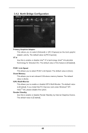
... [Enabled]. The default value is [Enabled]. 49 PCIE1 Link Speed This allows you to set onboard VGA share memory feature. The default value is [Auto]. IGPU Multi-Moniter This allows you to select [Onboard] or [PCI Express] as the boot graphic adapter priority. 3.4.2 North Bridge Configuration Primary Graphics Adapter This allows you to enable or disable IGPU Multi-Moniter. Render Standby Use this feature is [Auto]. VT-d Use this option. If you install the PCI Express card...
... [Enabled]. The default value is [Enabled]. 49 PCIE1 Link Speed This allows you to set onboard VGA share memory feature. The default value is [Auto]. IGPU Multi-Moniter This allows you to select [Onboard] or [PCI Express] as the boot graphic adapter priority. 3.4.2 North Bridge Configuration Primary Graphics Adapter This allows you to enable or disable IGPU Multi-Moniter. Render Standby Use this feature is [Auto]. VT-d Use this option. If you install the PCI Express card...
User Manual
Page 56
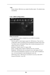
... refer to below descriptions for USB devices. If you enable Fast Boot option. USB devices are not allowed to use only under legacy OS and UEFI setup when [Disabled] is selected. There are connected. [Disabled] - The default value is [Enabled]. The default value is [Enabled]. 3.4.9 USB Configuration USB 2.0 Controller Use this option to select legacy support for the details of USB 2.0 controller. CSM Please disable CSM when you have USB compatibility issue, it is recommended to select [Disabled] to enter OS. [UEFI Setup Only] - Enables support for legacy USB. [Auto] -
... refer to below descriptions for USB devices. If you enable Fast Boot option. USB devices are not allowed to use only under legacy OS and UEFI setup when [Disabled] is selected. There are connected. [Disabled] - The default value is [Enabled]. The default value is [Enabled]. 3.4.9 USB Configuration USB 2.0 Controller Use this option to select legacy support for the details of USB 2.0 controller. CSM Please disable CSM when you have USB compatibility issue, it is recommended to select [Disabled] to enter OS. [UEFI Setup Only] - Enables support for legacy USB. [Auto] -
User Manual
Page 59
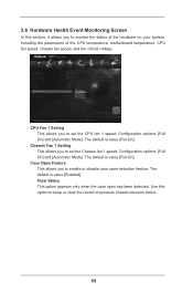
... the parameters of previous chassis intrusion status. 59 3.6 Hardware Health Event Monitoring Screen In this option to keep or clear the record of the CPU temperature, motherboard temperature, CPU fan speed, chassis fan speed, and the critical voltage. Configuration options: [Full On] and [Automatic Mode]. The default is value [Enabled]. The default is value [Full On]. The default is value [Full On]. Use this section, it allows you to enable or disable case open has been detected...
... the parameters of previous chassis intrusion status. 59 3.6 Hardware Health Event Monitoring Screen In this option to keep or clear the record of the CPU temperature, motherboard temperature, CPU fan speed, chassis fan speed, and the critical voltage. Configuration options: [Full On] and [Automatic Mode]. The default is value [Enabled]. The default is value [Full On]. The default is value [Full On]. Use this section, it allows you to enable or disable case open has been detected...
User Manual
Page 60
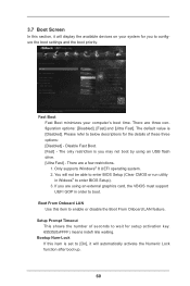
... are using an USB flash drive. [Ultra Fast] - 3.7 Boot Screen In this item is set to [On], it will display the available devices on your computer's boot time. The only restriction is [Disabled]. There are a few restrictions. 1. Boot From Onboard LAN Use this item to configure the boot settings and the boot priority. The default value is you to enable or disable the Boot From Onboard LAN feature. Fast Boot Fast Boot minimizes your system for setup activation key...
... are using an USB flash drive. [Ultra Fast] - 3.7 Boot Screen In this item is set to [On], it will display the available devices on your computer's boot time. The only restriction is [Disabled]. There are a few restrictions. 1. Boot From Onboard LAN Use this item to configure the boot settings and the boot priority. The default value is you to enable or disable the Boot From Onboard LAN feature. Fast Boot Fast Boot minimizes your system for setup activation key...
User Manual
Page 64
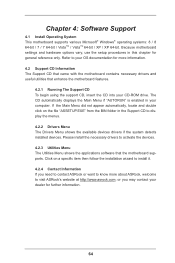
...-ROM drive. Chapter 4: Software Support 4.1 Install Operating System This motherboard supports various Microsoft® Windows® operating systems: 8 / 8 64-bit / 7 / 7 64-bit / VistaTM / VistaTM 64-bit / XP / XP 64-bit. If the Main Menu did not appear automatically, locate and double click on a specific item then follow the installation wizard to activate the devices. 4.2.3 Utilities Menu The Utilities Menu shows the applications software that enhance the motherboard features. 4.2.1 Running The Support CD To begin using the support...
...-ROM drive. Chapter 4: Software Support 4.1 Install Operating System This motherboard supports various Microsoft® Windows® operating systems: 8 / 8 64-bit / 7 / 7 64-bit / VistaTM / VistaTM 64-bit / XP / XP 64-bit. If the Main Menu did not appear automatically, locate and double click on a specific item then follow the installation wizard to activate the devices. 4.2.3 Utilities Menu The Utilities Menu shows the applications software that enhance the motherboard features. 4.2.1 Running The Support CD To begin using the support...
Quick Installation Guide
Page 2
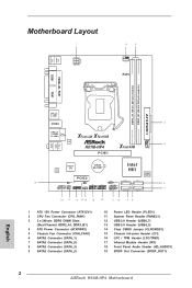
... 3 2 x 240-pin DDR3 DIMM Slots (Dual Channel: DDR3_A1, DDR3_B1) 4 ATX Power Connector (ATXPWR1) 5 Chassis Fan Connector (CHA_FAN1) 6 SATA2 Connector (SATA_1) 7 SATA2 Connector (SATA_0) 8 SATA2 Connector (SATA_3) 9 SATA2 Connector (SATA_2) 10 Power LED Header (PLED1) 11 System Panel Header (PANEL1) 12 USB 2.0 Header (USB6_7) 13 USB 2.0 Header (USB4_5) 14 Clear CMOS Jumper (CLRCMOS1) 15 Chassis Intrusion Header (CI1) 16 LPC / TPM Header (LPC/TPM1) 17 Infrared Module Header (IR1) 18 Front Panel Audio Header (HD_AUDIO1) 19 SPDIF Out Connector (SPDIF_OUT1) 2 ASRock H61M-HP4 Motherboard English
... 3 2 x 240-pin DDR3 DIMM Slots (Dual Channel: DDR3_A1, DDR3_B1) 4 ATX Power Connector (ATXPWR1) 5 Chassis Fan Connector (CHA_FAN1) 6 SATA2 Connector (SATA_1) 7 SATA2 Connector (SATA_0) 8 SATA2 Connector (SATA_3) 9 SATA2 Connector (SATA_2) 10 Power LED Header (PLED1) 11 System Panel Header (PANEL1) 12 USB 2.0 Header (USB6_7) 13 USB 2.0 Header (USB4_5) 14 Clear CMOS Jumper (CLRCMOS1) 15 Chassis Intrusion Header (CI1) 16 LPC / TPM Header (LPC/TPM1) 17 Infrared Module Header (IR1) 18 Front Panel Audio Header (HD_AUDIO1) 19 SPDIF Out Connector (SPDIF_OUT1) 2 ASRock H61M-HP4 Motherboard English


