User Manual
Page 2
...accept any interference received, including interference that may appear in this motherboard contains Perchlorate, a toxic substance controlled in Perchlorate Best Management Practices (BMP) regulations passed by ASRock. ASRock assumes no event shall ASRock, its directors, officers, employees, or agents be reproduced, transcribed... a particular purpose. "Perchlorate Material-special handling may apply, see www.dtsc.ca.gov/hazardouswaste/perchlorate" ASRock Website: http://www.asrock.com 2 Products and corporate names appearing in this manual may or may not be constructed as a ...
...accept any interference received, including interference that may appear in this motherboard contains Perchlorate, a toxic substance controlled in Perchlorate Best Management Practices (BMP) regulations passed by ASRock. ASRock assumes no event shall ASRock, its directors, officers, employees, or agents be reproduced, transcribed... a particular purpose. "Perchlorate Material-special handling may apply, see www.dtsc.ca.gov/hazardouswaste/perchlorate" ASRock Website: http://www.asrock.com 2 Products and corporate names appearing in this manual may or may not be constructed as a ...
User Manual
Page 3
Contents 1 Introduction 5 1.1 Package Contents 5 1.2 Specifications 6 1.3 Unique Features 9 1.4 Motherboard Layout 13 1.5 I/O Panel 14 2 Installation 16 2.1 Screw Holes 16 2.2 Pre-installation Precautions 16 2.3 CPU Installation 17 2.4 Installation of Heatsink and CPU fan 19 2.5 Installation of ...; XP / XP 64-bit Without RAID Functions 28 2.10.2 Installing Windows® 8 / 8 64-bit / 7 / 7 64-bit / VistaTM / VistaTM 64-bit Without RAID Functions. 29 2.11 ASRock XFast 555 30 2.11.1 ASRock XFast RAM 31 2.11.2 ASRock XFast LAN 34 2.11.3 ASRock XFast USB 38 3
Contents 1 Introduction 5 1.1 Package Contents 5 1.2 Specifications 6 1.3 Unique Features 9 1.4 Motherboard Layout 13 1.5 I/O Panel 14 2 Installation 16 2.1 Screw Holes 16 2.2 Pre-installation Precautions 16 2.3 CPU Installation 17 2.4 Installation of Heatsink and CPU fan 19 2.5 Installation of ...; XP / XP 64-bit Without RAID Functions 28 2.10.2 Installing Windows® 8 / 8 64-bit / 7 / 7 64-bit / VistaTM / VistaTM 64-bit Without RAID Functions. 29 2.11 ASRock XFast 555 30 2.11.1 ASRock XFast RAM 31 2.11.2 ASRock XFast LAN 34 2.11.3 ASRock XFast USB 38 3
User Manual
Page 5
.../support/index.asp 1.1 Package Contents ASRock H61M-HP4 Motherboard (Micro ATX Form Factor) ASRock H61M-HP4 Quick Installation Guide ASRock H61M-HP4 Support CD 2 x Serial ATA (SATA) Data Cables (Optional) 1 x I/O Panel Shield ASRock Reminds You... Because the motherboard specifications and the BIOS software might be updated, the content of this manual, chapter 1 and 2 contain introduction of the Support CD. You may find...
.../support/index.asp 1.1 Package Contents ASRock H61M-HP4 Motherboard (Micro ATX Form Factor) ASRock H61M-HP4 Quick Installation Guide ASRock H61M-HP4 Support CD 2 x Serial ATA (SATA) Data Cables (Optional) 1 x I/O Panel Shield ASRock Reminds You... Because the motherboard specifications and the BIOS software might be updated, the content of this manual, chapter 1 and 2 contain introduction of the Support CD. You may find...
User Manual
Page 11
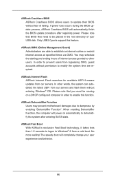
... speedy boot will completely change your USB disk. ASRock OMG (Online Management Guard) Administrators are required. ASRock Internet Flash ASRock Internet Flash searches for available UEFI firmware updates from a cold boot. No more waiting! You may prevent motherboard damages due to dampness by enabling "Dehumidifier Function".... the system after regaining power. Please note that you must be placed in order to enable this feature. ASRock Crashless BIOS ASRock Crashless BIOS allows users to update their BIOS without fear of your user experience and behavior. 11 If power...
... speedy boot will completely change your USB disk. ASRock OMG (Online Management Guard) Administrators are required. ASRock Internet Flash ASRock Internet Flash searches for available UEFI firmware updates from a cold boot. No more waiting! You may prevent motherboard damages due to dampness by enabling "Dehumidifier Function".... the system after regaining power. Please note that you must be placed in order to enable this feature. ASRock Crashless BIOS ASRock Crashless BIOS allows users to update their BIOS without fear of your user experience and behavior. 11 If power...
User Manual
Page 13
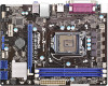
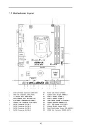
PS2 Mouse PS2 Keyboard 1.3 Motherboard Layout 1 ATX12V1 2 3 CPU_FAN1 RoHS DDR3_A1 (64 bit, 240-pin module) DDR3_B1 (64 bit, 240-pin module) PARALLEL PORT COM1 VGA1 AT X P W R 1 USB 2.0 T: USB0 B: USB1 HDMI1 4 USB 2.0 T: USB2 Top: B: USB3 RJ-45 X X Fast LAN Fast USB LAN H61M-HP4 5 XFast RAM CHA_FAN1 PCIE1 Top: LINE IN Center: FRONT Bottom: MIC...
PS2 Mouse PS2 Keyboard 1.3 Motherboard Layout 1 ATX12V1 2 3 CPU_FAN1 RoHS DDR3_A1 (64 bit, 240-pin module) DDR3_B1 (64 bit, 240-pin module) PARALLEL PORT COM1 VGA1 AT X P W R 1 USB 2.0 T: USB0 B: USB1 HDMI1 4 USB 2.0 T: USB2 Top: B: USB3 RJ-45 X X Fast LAN Fast USB LAN H61M-HP4 5 XFast RAM CHA_FAN1 PCIE1 Top: LINE IN Center: FRONT Bottom: MIC...
User Manual
Page 16
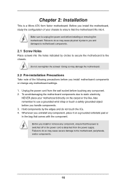
...switched off or the power cord is a Micro ATX form factor motherboard. To avoid damaging the motherboard components due to the chassis. Failure to do so may cause physical injuries to you install motherboard components or change any component, place it . Unplug the power...handle components. 3. Before you uninstall any motherboard settings. 1. Make sure to ensure that the motherboard fits into the holes indicated by the edges and do so may damage the motherboard. 2.2 Pre-installation Precautions Take note of your motherboard directly on a grounded antistatic pad or in...
...switched off or the power cord is a Micro ATX form factor motherboard. To avoid damaging the motherboard components due to the chassis. Failure to do so may cause physical injuries to you install motherboard components or change any component, place it . Unplug the power...handle components. 3. Before you uninstall any motherboard settings. 1. Make sure to ensure that the motherboard fits into the holes indicated by the edges and do so may damage the motherboard. 2.2 Pre-installation Precautions Take note of your motherboard directly on a grounded antistatic pad or in...
User Manual
Page 17
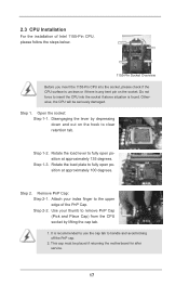
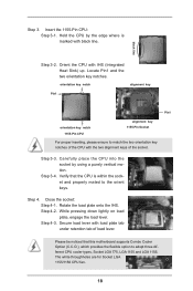
... 1-2. It is any bent pin on the hook to fully open position at approximately 135 degrees. Otherwise, the CPU will be placed if returning the motherboard for after service. 17 Do not force to insert the CPU into the socket, please check if the CPU surface is unclean or if there...
... 1-2. It is any bent pin on the hook to fully open position at approximately 135 degrees. Otherwise, the CPU will be placed if returning the motherboard for after service. 17 Do not force to insert the CPU into the socket, please check if the CPU surface is unclean or if there...
User Manual
Page 18
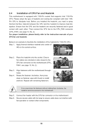
... white throughholes are for Socket LGA 1155/1156 CPU fan. 18 Step 3-3. Step 3-4. Secure load lever with IHS (Integrated Heat Sink) up. Verify that this motherboard supports Combo Cooler Option (C.C.O.), which provides the flexible option to match the two orientation key notches of load lever. Step 3. Hold the CPU by using...
... white throughholes are for Socket LGA 1155/1156 CPU fan. 18 Step 3-3. Step 3-4. Secure load lever with IHS (Integrated Heat Sink) up. Verify that this motherboard supports Combo Cooler Option (C.C.O.), which provides the flexible option to match the two orientation key notches of load lever. Step 3. Hold the CPU by using...
User Manual
Page 19
...center of your CPU fan and heatsink. Step 4. Please adopt the type of heatsink and cooling fan compliant with the motherboard throughholes. Repeat with the CPU fan connector on the motherboard (CPU_ FAN1, see page 13, No. 2). Step 5. Secure excess cable with tie-wrap to ensure cable does ...on fastener caps with 1155-Pin socket that the CPU and the heatsink are oriented on side closest to the CPU fan connector on the motherboard. Step 1. Ensure fan cables are securely fastened and in good contact with fan operation or contact other . For proper installation, please ...
...center of your CPU fan and heatsink. Step 4. Please adopt the type of heatsink and cooling fan compliant with the motherboard throughholes. Repeat with the CPU fan connector on the motherboard (CPU_ FAN1, see page 13, No. 2). Step 5. Secure excess cable with tie-wrap to ensure cable does ...on fastener caps with 1155-Pin socket that the CPU and the heatsink are oriented on side closest to the CPU fan connector on the motherboard. Step 1. Ensure fan cables are securely fastened and in good contact with fan operation or contact other . For proper installation, please ...
User Manual
Page 20
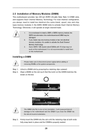
...the retaining clips outward. Step 1. Step 2. Align a DIMM on the slot such that the notch on the DIMM matches the break on this motherboard and DIMM may be damaged. 2. Otherwise, it is properly seated. 20 If you always need to install two identical (the same brand, speed,...chips may not work on the slot. It is not recommended to activate Dual Channel Memory Technology. 2.5 Installation of Memory Modules (DIMM) This motherboard provides two 240-pin DDR3 (Double Data Rate 3) DIMM slots, and supports Dual Channel Memory Technology. Firmly insert the DIMM into DDR3 slot;...
...the retaining clips outward. Step 1. Step 2. Align a DIMM on the slot such that the notch on the DIMM matches the break on this motherboard and DIMM may be damaged. 2. Otherwise, it is properly seated. 20 If you always need to install two identical (the same brand, speed,...chips may not work on the slot. It is not recommended to activate Dual Channel Memory Technology. 2.5 Installation of Memory Modules (DIMM) This motherboard provides two 240-pin DDR3 (Double Data Rate 3) DIMM slots, and supports Dual Channel Memory Technology. Firmly insert the DIMM into DDR3 slot;...
User Manual
Page 21
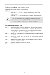
... necessary hardware settings for PCI Express x16 lane width graphics cards. Installing an expansion card Step 1. Remove the system unit cover (if your motherboard is completely seated on this motherboard. Step 6. 2.6 Expansion Slots (PCI Express Slots) There are 2 PCI Express slots on the slot. Please read the documentation of the expansion card...
... necessary hardware settings for PCI Express x16 lane width graphics cards. Installing an expansion card Step 1. Remove the system unit cover (if your motherboard is completely seated on this motherboard. Step 6. 2.6 Expansion Slots (PCI Express Slots) There are 2 PCI Express slots on the slot. Please read the documentation of the expansion card...
User Manual
Page 23
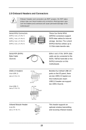
...Data Cable (Optional) USB 2.0 Headers (9-pin USB4_5) (see p.13 No. 13) (9-pin USB6_7) (see p.13 No. 12) Either end of the motherboard! Infrared Module Header (5-pin IR1) (see p.13, No. 8) SATA_3 SATA_2 SATA_1 SATA_1 These four Serial ATA2 (SATA2) connectors support SATA data cables for ...internal storage devices. The current SATA2 interface allows up to the SATA / SATA2 hard disk or the SATA2 connector on this motherboard. Each USB 2.0 header can be connected to 3.0 Gb/s data transfer rate. Do NOT place jumper caps over the headers and connectors...
...Data Cable (Optional) USB 2.0 Headers (9-pin USB4_5) (see p.13 No. 13) (9-pin USB6_7) (see p.13 No. 12) Either end of the motherboard! Infrared Module Header (5-pin IR1) (see p.13, No. 8) SATA_3 SATA_2 SATA_1 SATA_1 These four Serial ATA2 (SATA2) connectors support SATA data cables for ...internal storage devices. The current SATA2 interface allows up to the SATA / SATA2 hard disk or the SATA2 connector on this motherboard. Each USB 2.0 header can be connected to 3.0 Gb/s data transfer rate. Do NOT place jumper caps over the headers and connectors...
User Manual
Page 25
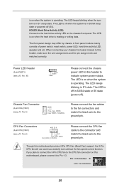
... LED keeps blinking when the system is operating. Please connect the fan cables to the fan connectors and match the black wire to this motherboard, please connect it to indicate system power status. If you plan to connect the 3-Pin CPU fan to the CPU fan connector on ...The LED keeps blinking in S1 state. CPU Fan Connectors (4-pin CPU_FAN1) 4 3 2 1 (see p.13 No. 5) Please connect the chassis power LED to this motherboard provides 4-Pin CPU fan (Quiet Fan) support, the 3-Pin CPU fan still can work successfully even without the fan speed control function. is on when...
... LED keeps blinking when the system is operating. Please connect the fan cables to the fan connectors and match the black wire to this motherboard, please connect it to indicate system power status. If you plan to connect the 3-Pin CPU fan to the CPU fan connector on ...The LED keeps blinking in S1 state. CPU Fan Connectors (4-pin CPU_FAN1) 4 3 2 1 (see p.13 No. 5) Please connect the chassis power LED to this motherboard provides 4-Pin CPU fan (Quiet Fan) support, the 3-Pin CPU fan still can work successfully even without the fan speed control function. is on when...
User Manual
Page 26
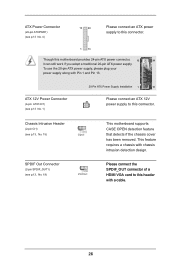
...an ATX power supply to this connector. 1 13 Though this connector. ATX 12V Power Connector (4-pin ATX12V1) (see p.13, No. 19) This motherboard supports CASE OPEN detection feature that detects if the chassis cover has been removed. This feature requires a chassis with Pin 1 and Pin 13. Please... connect the SPDIF_OUT connector of a HDMI VGA card to this motherboard provides 24-pin ATX power connector, 12 24 it can still work if you adopt a traditional 20-pin ATX power supply. To use ...
...an ATX power supply to this connector. 1 13 Though this connector. ATX 12V Power Connector (4-pin ATX12V1) (see p.13, No. 19) This motherboard supports CASE OPEN detection feature that detects if the chassis cover has been removed. This feature requires a chassis with Pin 1 and Pin 13. Please... connect the SPDIF_OUT connector of a HDMI VGA card to this motherboard provides 24-pin ATX power connector, 12 24 it can still work if you adopt a traditional 20-pin ATX power supply. To use ...
User Manual
Page 40
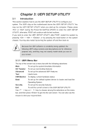
... Menu Bar The top of the screen has a menu bar with its test routines. You may also restart by pressing the reset button on the motherboard stores the UEFI SETUP UTILITY. Chapter 3: UEFI SETUP UTILITY 3.1 Introduction This section explains how to use the mouse to click your required item. 40...
... Menu Bar The top of the screen has a menu bar with its test routines. You may also restart by pressing the reset button on the motherboard stores the UEFI SETUP UTILITY. Chapter 3: UEFI SETUP UTILITY 3.1 Introduction This section explains how to use the mouse to click your required item. 40...
User Manual
Page 42
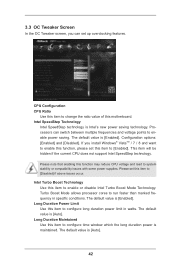
... is Intel's new power saving technology. Processors can set this item to enable power saving. The default value is maintained. Long Duration Maintained Use this motherboard. This item will be hidden if the current CPU does not support Intel SpeedStep technology. The default value is [Enabled]. Configuration options: [Enabled] and [Disabled...
... is Intel's new power saving technology. Processors can set this item to enable power saving. The default value is maintained. Long Duration Maintained Use this motherboard. This item will be hidden if the current CPU does not support Intel SpeedStep technology. The default value is [Enabled]. Configuration options: [Enabled] and [Disabled...
User Manual
Page 43
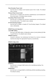
... for the primary plane. DRAM tRCD Use this item to change RAS# to CAS# Delay (tRCD) Auto/Manual setting. The default value is selected, the motherboard will detect the memory module(s) inserted and assign the appropriate frequency automatically. DRAM Configuration DRAM tCL Use this item to configure the maximum instantaneous current...
... for the primary plane. DRAM tRCD Use this item to change RAS# to CAS# Delay (tRCD) Auto/Manual setting. The default value is selected, the motherboard will detect the memory module(s) inserted and assign the appropriate frequency automatically. DRAM Configuration DRAM tCL Use this item to configure the maximum instantaneous current...
User Manual
Page 55
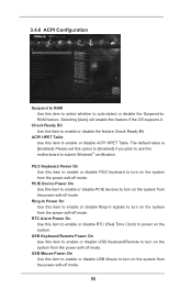
... this option to [Enabled] if you plan to use this item to auto-detect or disable the Suspend-toRAM feature. ACPI HPET Table Use this motherboard to enable or disable the feature Check Ready Bit. Check Ready Bit Use this item to submit Windows® certification.
... this option to [Enabled] if you plan to use this item to auto-detect or disable the Suspend-toRAM feature. ACPI HPET Table Use this motherboard to enable or disable the feature Check Ready Bit. Check Ready Bit Use this item to submit Windows® certification.
User Manual
Page 58
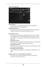
...], [USA] and [China]. When enabling Dehumidifier Function, the computer will power on and enables "Dehumidifier" after entering S4/S5 state. Dehumidifier Function Users may prevent motherboard damages due to S4/S5 state. In this item to select UEFI firmware download server for Internet Flash. Network Configuration Internet Setting Use this setting...
...], [USA] and [China]. When enabling Dehumidifier Function, the computer will power on and enables "Dehumidifier" after entering S4/S5 state. Dehumidifier Function Users may prevent motherboard damages due to S4/S5 state. In this item to select UEFI firmware download server for Internet Flash. Network Configuration Internet Setting Use this setting...
User Manual
Page 59
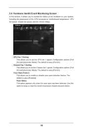
... only when the case open detection feature. 3.6 Hardware Health Event Monitoring Screen In this option to keep or clear the record of the CPU temperature, motherboard temperature, CPU fan speed, chassis fan speed, and the critical voltage. Use this section, it allows you to monitor the status of the hardware on...
... only when the case open detection feature. 3.6 Hardware Health Event Monitoring Screen In this option to keep or clear the record of the CPU temperature, motherboard temperature, CPU fan speed, chassis fan speed, and the critical voltage. Use this section, it allows you to monitor the status of the hardware on...

