User Manual
Page 2
... and to infringe. This device complies with Part 15 of merchantability or fitness for backup purpose, without written consent of ASRock Inc. CALIFORNIA, USA ONLY The Lithium battery adopted on this motherboard contains Perchlorate, a toxic substance controlled in Perchlorate Best Management Practices (BMP) regulations passed by the purchaser for a particular purpose. In...
... and to infringe. This device complies with Part 15 of merchantability or fitness for backup purpose, without written consent of ASRock Inc. CALIFORNIA, USA ONLY The Lithium battery adopted on this motherboard contains Perchlorate, a toxic substance controlled in Perchlorate Best Management Practices (BMP) regulations passed by the purchaser for a particular purpose. In...
User Manual
Page 3
Contents 1 Introduction 5 1.1 Package Contents 5 1.2 Specifications 6 1.3 Unique Features 9 1.4 Motherboard Layout 13 1.5 I/O Panel 14 2 Installation 16 2.1 Screw Holes 16 2.2 Pre-installation Precautions 16 2.3 CPU Installation 17 2.4 Installation of Heatsink and CPU fan 19 2.5 Installation of ...; XP / XP 64-bit Without RAID Functions 28 2.10.2 Installing Windows® 8 / 8 64-bit / 7 / 7 64-bit / VistaTM / VistaTM 64-bit Without RAID Functions. 29 2.11 ASRock XFast 555 30 2.11.1 ASRock XFast RAM 31 2.11.2 ASRock XFast LAN 34 2.11.3 ASRock XFast USB 38 3
Contents 1 Introduction 5 1.1 Package Contents 5 1.2 Specifications 6 1.3 Unique Features 9 1.4 Motherboard Layout 13 1.5 I/O Panel 14 2 Installation 16 2.1 Screw Holes 16 2.2 Pre-installation Precautions 16 2.3 CPU Installation 17 2.4 Installation of Heatsink and CPU fan 19 2.5 Installation of ...; XP / XP 64-bit Without RAID Functions 28 2.10.2 Installing Windows® 8 / 8 64-bit / 7 / 7 64-bit / VistaTM / VistaTM 64-bit Without RAID Functions. 29 2.11 ASRock XFast 555 30 2.11.1 ASRock XFast RAM 31 2.11.2 ASRock XFast LAN 34 2.11.3 ASRock XFast USB 38 3
User Manual
Page 5
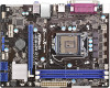
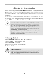
... website for specific information about the model you for purchasing ASRock H61M-HP4 motherboard, a reliable motherboard produced under ASRock's consistently stringent quality control. www.asrock.com/support/index.asp 1.1 Package Contents ASRock H61M-HP4 Motherboard (Micro ATX Form Factor) ASRock H61M-HP4 Quick Installation Guide ASRock H61M-HP4 Support CD 2 x Serial ATA (SATA) Data Cables (Optional) 1 x I/O Panel Shield ASRock Reminds You... It delivers excellent performance with robust design...
... website for specific information about the model you for purchasing ASRock H61M-HP4 motherboard, a reliable motherboard produced under ASRock's consistently stringent quality control. www.asrock.com/support/index.asp 1.1 Package Contents ASRock H61M-HP4 Motherboard (Micro ATX Form Factor) ASRock H61M-HP4 Quick Installation Guide ASRock H61M-HP4 Support CD 2 x Serial ATA (SATA) Data Cables (Optional) 1 x I/O Panel Shield ASRock Reminds You... It delivers excellent performance with robust design...
User Manual
Page 11
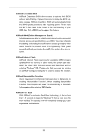
... that you must be placed in order to enable this feature. Only USB2.0 ports support this function. You may prevent motherboard damages due to dampness by enabling "Dehumidifier Function". When enabling Dehumidifier Function, the computer will automatically finish the BIOS update procedure... after entering S4/S5 state. ASRock Crashless BIOS ASRock Crashless BIOS allows users to update their BIOS without fear of internet access granted to other words, the system can ...
... that you must be placed in order to enable this feature. Only USB2.0 ports support this function. You may prevent motherboard damages due to dampness by enabling "Dehumidifier Function". When enabling Dehumidifier Function, the computer will automatically finish the BIOS update procedure... after entering S4/S5 state. ASRock Crashless BIOS ASRock Crashless BIOS allows users to update their BIOS without fear of internet access granted to other words, the system can ...
User Manual
Page 13
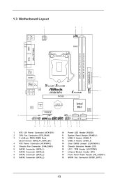
PS2 Mouse PS2 Keyboard 1.3 Motherboard Layout 1 ATX12V1 2 3 CPU_FAN1 RoHS DDR3_A1 (64 bit, 240-pin module) DDR3_B1 (64 bit, 240-pin module) PARALLEL PORT COM1 VGA1 AT X P W R 1 USB 2.0 T: USB0 B: USB1 HDMI1 4 USB 2.0 T: USB2 Top: B: USB3 RJ-45 X X Fast LAN Fast USB LAN H61M-HP4 5 XFast RAM CHA_FAN1 PCIE1 Top: LINE IN Center: FRONT Bottom: MIC...
PS2 Mouse PS2 Keyboard 1.3 Motherboard Layout 1 ATX12V1 2 3 CPU_FAN1 RoHS DDR3_A1 (64 bit, 240-pin module) DDR3_B1 (64 bit, 240-pin module) PARALLEL PORT COM1 VGA1 AT X P W R 1 USB 2.0 T: USB0 B: USB1 HDMI1 4 USB 2.0 T: USB2 Top: B: USB3 RJ-45 X X Fast LAN Fast USB LAN H61M-HP4 5 XFast RAM CHA_FAN1 PCIE1 Top: LINE IN Center: FRONT Bottom: MIC...
User Manual
Page 16
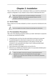
Do not over-tighten the screws! Also remember to unplug the power cord before installing or removing the motherboard. Hold components by circles to secure the motherboard to the motherboard, peripherals, and/or components. 16 Before you handle components. 3. Make sure to use a grounded wrist strap or touch a safety grounded object before you install...
Do not over-tighten the screws! Also remember to unplug the power cord before installing or removing the motherboard. Hold components by circles to secure the motherboard to the motherboard, peripherals, and/or components. 16 Before you handle components. 3. Make sure to use a grounded wrist strap or touch a safety grounded object before you install...
User Manual
Page 17
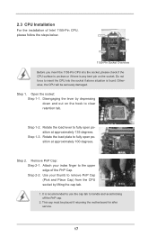
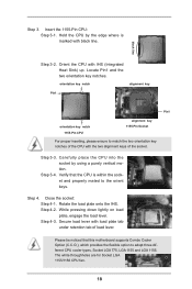
... load plate to clear retention tab. 2.3 CPU Installation For the installation of the PnP Cap. Step 1. Otherwise, the CPU will be placed if returning the motherboard for after service. 17 Step 2-2. Do not force to fully open position at approximately 135 degrees. Open the socket: Step 1-1. Disengaging the lever by lifting...
... load plate to clear retention tab. 2.3 CPU Installation For the installation of the PnP Cap. Step 1. Otherwise, the CPU will be placed if returning the motherboard for after service. 17 Step 2-2. Do not force to fully open position at approximately 135 degrees. Open the socket: Step 1-1. Disengaging the lever by lifting...
User Manual
Page 18
.... Carefully place the CPU into the socket by the edge where is within the socket and properly mated to the orient keys. Verify that this motherboard supports Combo Cooler Option (C.C.O.), which provides the flexible option to match the two orientation key notches of the socket. Step 3-4. Rotate the load plate onto...
.... Carefully place the CPU into the socket by the edge where is within the socket and properly mated to the orient keys. Verify that this motherboard supports Combo Cooler Option (C.C.O.), which provides the flexible option to match the two orientation key notches of the socket. Step 3-4. Rotate the load plate onto...
User Manual
Page 19
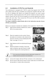
...IHS on the socket surface. Align fasteners with remaining fasteners. Apply thermal interface material onto center of CPU Fan and Heatsink This motherboard is an example to ensure cable does not interfere with Intel 1155Pin CPU to MB header Fastener slots pointing straight out Press Down ...compliant with fan operation or contact other . Ensure fan cables are securely fastened and in good contact with the CPU fan connector on the motherboard. Step 5. Step 6. Then connect the CPU fan to improve heat dissipation. Step 4. Rotate the fastener clockwise, then press down the...
...IHS on the socket surface. Align fasteners with remaining fasteners. Apply thermal interface material onto center of CPU Fan and Heatsink This motherboard is an example to ensure cable does not interfere with Intel 1155Pin CPU to MB header Fastener slots pointing straight out Press Down ...compliant with fan operation or contact other . Ensure fan cables are securely fastened and in good contact with the CPU fan connector on the motherboard. Step 5. Step 6. Then connect the CPU fan to improve heat dissipation. Step 4. Rotate the fastener clockwise, then press down the...
User Manual
Page 20
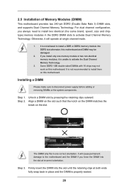
... make sure to install them on the slot. Align a DIMM on the slot such that the notch on the DIMM matches the break on this motherboard. Step 3. Some DDR3 1GB double-sided DIMMs with 16 chips may be damaged. 2. Unlock a DIMM slot by pressing the retaining clips outward. It.... 20 Step 1. It is unable to activate Dual Channel Memory Technology. Firmly insert the DIMM into DDR3 slot;otherwise, this motherboard and DIMM may not work on this motherboard. The DIMM only fits in one memory module or two non-identical memory modules, it will cause permanent damage to the...
... make sure to install them on the slot. Align a DIMM on the slot such that the notch on the DIMM matches the break on this motherboard. Step 3. Some DDR3 1GB double-sided DIMMs with 16 chips may be damaged. 2. Unlock a DIMM slot by pressing the retaining clips outward. It.... 20 Step 1. It is unable to activate Dual Channel Memory Technology. Firmly insert the DIMM into DDR3 slot;otherwise, this motherboard and DIMM may not work on this motherboard. The DIMM only fits in one memory module or two non-identical memory modules, it will cause permanent damage to the...
User Manual
Page 21
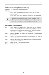
... 4. Align the card connector with screws. If you start the installation. Installing an expansion card Step 1. Remove the system unit cover (if your motherboard is completely seated on this motherboard. PCIE slots: PCIE1 (PCIE 3.0 x16 slot) is used for later use . Fasten the card to use . Replace the system cover. 21 Keep...
... 4. Align the card connector with screws. If you start the installation. Installing an expansion card Step 1. Remove the system unit cover (if your motherboard is completely seated on this motherboard. PCIE slots: PCIE1 (PCIE 3.0 x16 slot) is used for later use . Fasten the card to use . Replace the system cover. 21 Keep...
User Manual
Page 23
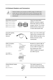
... connectors support SATA data cables for internal storage devices. 2.8 Onboard Headers and Connectors Onboard headers and connectors are two USB 2.0 headers on this motherboard. Serial ATA (SATA) Data Cable (Optional) USB 2.0 Headers (9-pin USB4_5) (see p.13 No. 13) (9-pin USB6_7) (see p.13 No.... 12) Either end of the motherboard! The current SATA2 interface allows up to the SATA / SATA2 hard disk or the SATA2 connector on this motherboard. Serial ATA2 Connectors (SATA_0: see p.13, No. 7) (SATA_1: see p.13, No. 6) (SATA_2:...
... connectors support SATA data cables for internal storage devices. 2.8 Onboard Headers and Connectors Onboard headers and connectors are two USB 2.0 headers on this motherboard. Serial ATA (SATA) Data Cable (Optional) USB 2.0 Headers (9-pin USB4_5) (see p.13 No. 13) (9-pin USB6_7) (see p.13 No.... 12) Either end of the motherboard! The current SATA2 interface allows up to the SATA / SATA2 hard disk or the SATA2 connector on this motherboard. Serial ATA2 Connectors (SATA_0: see p.13, No. 7) (SATA_1: see p.13, No. 6) (SATA_2:...
User Manual
Page 25
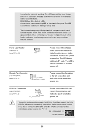
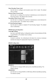
...this header to Pin 1-3. A front panel module mainly consists of power switch, reset switch, power LED, hard drive activity LED, speaker and etc. Though this motherboard, please connect it to indicate system power status. The LED is on when the system is operating. The LED is off in S3/S4 sleep...system is in S3/S4 state or S5 state (power off (S5). HDLED (Hard Drive Activity LED): Connect to the CPU fan connector on this motherboard provides 4-Pin CPU fan (Quiet Fan) support, the 3-Pin CPU fan still can work successfully even without the fan speed control function. If you ...
...this header to Pin 1-3. A front panel module mainly consists of power switch, reset switch, power LED, hard drive activity LED, speaker and etc. Though this motherboard, please connect it to indicate system power status. The LED is on when the system is operating. The LED is off in S3/S4 sleep...system is in S3/S4 state or S5 state (power off (S5). HDLED (Hard Drive Activity LED): Connect to the CPU fan connector on this motherboard provides 4-Pin CPU fan (Quiet Fan) support, the 3-Pin CPU fan still can work successfully even without the fan speed control function. If you ...
User Manual
Page 26
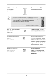
... supply along with chassis intrusion detection design. Please connect the SPDIF_OUT connector of a HDMI VGA card to this connector. 1 13 Though this motherboard provides 24-pin ATX power connector, 12 24 it can still work if you adopt a traditional 20-pin ATX power supply. ATX 12V... Power Connector (4-pin ATX12V1) (see p.13, No. 19) This motherboard supports CASE OPEN detection feature that detects if the chassis cover has been removed. Chassis Intrusion Header (2-pin CI1) (see p.13, No. 15)...
... supply along with chassis intrusion detection design. Please connect the SPDIF_OUT connector of a HDMI VGA card to this connector. 1 13 Though this motherboard provides 24-pin ATX power connector, 12 24 it can still work if you adopt a traditional 20-pin ATX power supply. ATX 12V... Power Connector (4-pin ATX12V1) (see p.13, No. 19) This motherboard supports CASE OPEN detection feature that detects if the chassis cover has been removed. Chassis Intrusion Header (2-pin CI1) (see p.13, No. 15)...
User Manual
Page 40
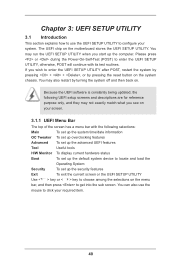
... (POST) to enter the UEFI SETUP UTILITY after POST, restart the system by pressing + + , or by turning the system off and then back on the motherboard stores the UEFI SETUP UTILITY. The UEFI chip on . You may run the UEFI SETUP UTILITY when you start up the security features Exit To...
... (POST) to enter the UEFI SETUP UTILITY after POST, restart the system by pressing + + , or by turning the system off and then back on the motherboard stores the UEFI SETUP UTILITY. The UEFI chip on . You may run the UEFI SETUP UTILITY when you start up the security features Exit To...
User Manual
Page 42
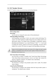
... to configure time window which the long duration power is maintained. CPU Configuration CPU Ratio Use this item to change the ratio value of this motherboard.
... to configure time window which the long duration power is maintained. CPU Configuration CPU Ratio Use this item to change the ratio value of this motherboard.
User Manual
Page 43
... default value is [Auto]. DRAM Timing Configuration Load XMP Setting Use this item to enable or disable GT OverClocking Support. The default is selected, the motherboard will detect the memory module(s) inserted and assign the appropriate frequency automatically. Short Duration Power Limit Use this item to change CAS# Latency (tCL) Auto...
... default value is [Auto]. DRAM Timing Configuration Load XMP Setting Use this item to enable or disable GT OverClocking Support. The default is selected, the motherboard will detect the memory module(s) inserted and assign the appropriate frequency automatically. Short Duration Power Limit Use this item to change CAS# Latency (tCL) Auto...
User Manual
Page 55
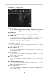
... to enable or disable USB Mouse to turn on the system from the power-soft-off mode. 55 USB Keyboard/Remote Power On Use this motherboard to submit Windows® certification. 3.4.8 ACPI Configuration Suspend to RAM Use this feature if the OS supports it. Please set this option to [Enabled] if...
... to enable or disable USB Mouse to turn on the system from the power-soft-off mode. 55 USB Keyboard/Remote Power On Use this motherboard to submit Windows® certification. 3.4.8 ACPI Configuration Suspend to RAM Use this feature if the OS supports it. Please set this option to [Enabled] if...
User Manual
Page 58
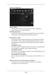
... this item to configure the duration of time until the computer powers on automatically to dampness by enabling "Dehumidifier Function". Dehumidifier Function Users may prevent motherboard damages due to dehumidify the system after entering S4/S5 state. Would you are allowed to S4/S5 state. When enabling Dehumidifier Function, the computer...
... this item to configure the duration of time until the computer powers on automatically to dampness by enabling "Dehumidifier Function". Dehumidifier Function Users may prevent motherboard damages due to dehumidify the system after entering S4/S5 state. Would you are allowed to S4/S5 state. When enabling Dehumidifier Function, the computer...
User Manual
Page 59
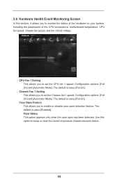
..., including the parameters of previous chassis intrusion status. 59 CPU Fan 1 Setting This allows you to keep or clear the record of the CPU temperature, motherboard temperature, CPU fan speed, chassis fan speed, and the critical voltage. Configuration options: [Full On] and [Automatic Mode]. Configuration options: [Full On] and [Automatic Mode...
..., including the parameters of previous chassis intrusion status. 59 CPU Fan 1 Setting This allows you to keep or clear the record of the CPU temperature, motherboard temperature, CPU fan speed, chassis fan speed, and the critical voltage. Configuration options: [Full On] and [Automatic Mode]. Configuration options: [Full On] and [Automatic Mode...

