User Manual
Page 4
...figuration 42 3.4.3 South Bridge Configuration 43 3.4.4 Storage Configuration 44 3.4.5 Super IO Configuration 45 3.4.6 ACPI Configuration 46 3.4.7 USB Configuration 47 3.5 Hardware Health Event Monitoring Screen 48 3.6 Boot Screen 49 3.7 Security Screen 50 3.8 Exit Screen 51 4 Software Support 52 4.1 Install Operating System...
...figuration 42 3.4.3 South Bridge Configuration 43 3.4.4 Storage Configuration 44 3.4.5 Super IO Configuration 45 3.4.6 ACPI Configuration 46 3.4.7 USB Configuration 47 3.5 Hardware Health Event Monitoring Screen 48 3.6 Boot Screen 49 3.7 Security Screen 50 3.8 Exit Screen 51 4 Software Support 52 4.1 Install Operating System...
User Manual
Page 7
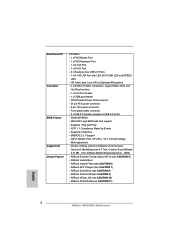
..., AntiVirus Software (Trial Version), CyberLink MediaEspresso 6.5 Trial, Creative Sound Blaster X-Fi MB - ASRock APP Charger (see CAUTION 8) - Front panel audio connector - 2 x USB 2.0 headers (support 4 USB 2.0 ports) - 32Mb AMI BIOS - Trial, ASRock MAGIX Multimedia Suite - ASRock XFast RAM (see CAUTION 9) - ASRock XFast USB (see CAUTION 11) 7 ASRock Instant Flash (see CAUTION 6) - SMBIOS 2.3.1 Support - Supports "Plug and Play" - IGPU, DRAM...
..., AntiVirus Software (Trial Version), CyberLink MediaEspresso 6.5 Trial, Creative Sound Blaster X-Fi MB - ASRock APP Charger (see CAUTION 8) - Front panel audio connector - 2 x USB 2.0 headers (support 4 USB 2.0 ports) - 32Mb AMI BIOS - Trial, ASRock MAGIX Multimedia Suite - ASRock XFast RAM (see CAUTION 9) - ASRock XFast USB (see CAUTION 11) 7 ASRock Instant Flash (see CAUTION 6) - SMBIOS 2.3.1 Support - Supports "Plug and Play" - IGPU, DRAM...
User Manual
Page 9
... Flash. About the setting of ASRock Extreme Tuning Utility (AXTU). In Hardware Monitor, it shows the fan speed and temperature for the operation procedures of "Hyper Threading Technology", please check page 40. 2. In Overclocking, you to utilize the memory that the USB flash drive or hard drive must use . 4. Please visit...
... Flash. About the setting of ASRock Extreme Tuning Utility (AXTU). In Hardware Monitor, it shows the fan speed and temperature for the operation procedures of "Hyper Threading Technology", please check page 40. 2. In Overclocking, you to utilize the memory that the USB flash drive or hard drive must use . 4. Please visit...
User Manual
Page 10
... used under Windows® OS 32-bit CPU. Traffic Shaping: You can boost USB storage device performance. And it can easily recognize which includes below benefits. ASRock motherboards are currently transferring. 11. Combo Cooler Option (C.C.O.) provides the flexible option to...bit / VistaTM / VistaTM 64 bit, and your computer and up to RAM (S3), hibernation mode (S4) or power off (S5). ASRock APP Charger. ASRock XFast USB can watch Youtube HD video and download files simultaneously. Real-Time Analysis of Your Data: With the status window, you desire a...
... used under Windows® OS 32-bit CPU. Traffic Shaping: You can boost USB storage device performance. And it can easily recognize which includes below benefits. ASRock motherboards are currently transferring. 11. Combo Cooler Option (C.C.O.) provides the flexible option to...bit / VistaTM / VistaTM 64 bit, and your computer and up to RAM (S3), hibernation mode (S4) or power off (S5). ASRock APP Charger. ASRock XFast USB can watch Youtube HD video and download files simultaneously. Real-Time Analysis of Your Data: With the status window, you desire a...

User Manual
Page 12
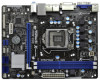
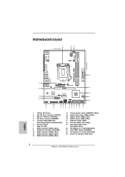
...LAN PHY 5 22 PCIE1 Designed in ) DDR3_B1 (64 bit, 240-pin module) DDR3_A1 (64 bit, 240-pin module) DVI1 ErP/EuP Ready DDR3 USB 2.0 T: USB0 B: USB1 4 USB 2.0 T: USB2 B: USB3 USB 2.0 T: USB4 B: USB5 Top: RJ-45 23 Top: LINE IN Center: FRONT Bottom: MIC IN XFast RAM H 6 1 M - VGA1 ...PS2 Mouse PS2 Keyboard 1.3 Motherboard Layout 1 17.3cm (6.8 in) 23 CPU_FAN1 ATX12V1 RoHS Fast USB X Fast LAN X AT X P W R 1 22.6cm (8.9 in Taipei AUDIO CODEC Super I/O CLRCMOS1 1 CMOS 21 Battery 20 PCIE2 Intel 6 H61 32Mb BIOS 7...
...LAN PHY 5 22 PCIE1 Designed in ) DDR3_B1 (64 bit, 240-pin module) DDR3_A1 (64 bit, 240-pin module) DVI1 ErP/EuP Ready DDR3 USB 2.0 T: USB0 B: USB1 4 USB 2.0 T: USB2 B: USB3 USB 2.0 T: USB4 B: USB5 Top: RJ-45 23 Top: LINE IN Center: FRONT Bottom: MIC IN XFast RAM H 6 1 M - VGA1 ...PS2 Mouse PS2 Keyboard 1.3 Motherboard Layout 1 17.3cm (6.8 in) 23 CPU_FAN1 ATX12V1 RoHS Fast USB X Fast LAN X AT X P W R 1 22.6cm (8.9 in Taipei AUDIO CODEC Super I/O CLRCMOS1 1 CMOS 21 Battery 20 PCIE2 Intel 6 H61 32Mb BIOS 7...
User Manual
Page 13
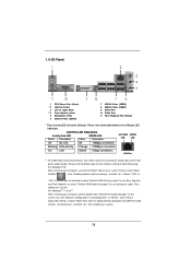
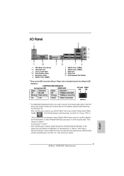
..." tool on the system tray. 1.4 I/O Panel 1 PS/2 Mouse Port (Green) * 2 LAN RJ-45 Port 3 Line In (Light Blue) ** 4 Front Speaker (Lime) 5 Microphone (Pink) 6 USB 2.0 Ports (USB45) 7 USB 2.0 Ports (USB23) 8 USB 2.0 Ports (USB01) 9 DVI-D Port 10 D-Sub Port 11 PS/2 Keyboard Port (Purple) * There are allowed to select "Realtek HDA Primary output" to use...
..." tool on the system tray. 1.4 I/O Panel 1 PS/2 Mouse Port (Green) * 2 LAN RJ-45 Port 3 Line In (Light Blue) ** 4 Front Speaker (Lime) 5 Microphone (Pink) 6 USB 2.0 Ports (USB45) 7 USB 2.0 Ports (USB23) 8 USB 2.0 Ports (USB01) 9 DVI-D Port 10 D-Sub Port 11 PS/2 Keyboard Port (Purple) * There are allowed to select "Realtek HDA Primary output" to use...
User Manual
Page 24
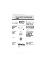
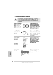
...PINIT# SLIN# GND 1 SPD7 SPD6 ACK# SPD5 BUSY SPD4 PE SPD3 SLCT SPD2 SPD1 SPD0 STB# This is an interface for internal storage devices. USB 2.0 Headers (9-pin USB6_7) (see p.12 No. 15) (9-pin USB8_9) (see p.12, No. 11) SATA2_3 SATA2_1 SATA2_2 SATA2_0 These four ... Placing jumper caps over these headers and connectors. Serial ATA (SATA) Data Cable (Optional) Either end of the SATA data cable can support two USB 2.0 ports. Each USB 2.0 header can be connected to 3.0 Gb/s data transfer rate. Serial ATAII Connectors (SATA2_0: see p.12, No. 10) (SATA2_1: see p....
...PINIT# SLIN# GND 1 SPD7 SPD6 ACK# SPD5 BUSY SPD4 PE SPD3 SLCT SPD2 SPD1 SPD0 STB# This is an interface for internal storage devices. USB 2.0 Headers (9-pin USB6_7) (see p.12 No. 15) (9-pin USB8_9) (see p.12, No. 11) SATA2_3 SATA2_1 SATA2_2 SATA2_0 These four ... Placing jumper caps over these headers and connectors. Serial ATA (SATA) Data Cable (Optional) Either end of the SATA data cable can support two USB 2.0 ports. Each USB 2.0 header can be connected to 3.0 Gb/s data transfer rate. Serial ATAII Connectors (SATA2_0: see p.12, No. 10) (SATA2_1: see p....
User Manual
Page 31
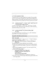
...figuration. B. B. E. Please select CD-ROM as the boot device. C. Then, the drivers compatible to your system. STEP 2: Make a SATA / SATAII driver diskette. (Please use USB floppy or floppy disk.) A. Using SATA / SATAII HDDs with NCQ function STEP 1: Set Up UEFI. When you see these messages, Please insert a diskette...
...figuration. B. B. E. Please select CD-ROM as the boot device. C. Then, the drivers compatible to your system. STEP 2: Make a SATA / SATAII driver diskette. (Please use USB floppy or floppy disk.) A. Using SATA / SATAII HDDs with NCQ function STEP 1: Set Up UEFI. When you see these messages, Please insert a diskette...
User Manual
Page 39
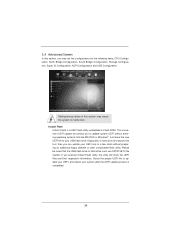
...in a few clicks without entering operating systems first like MS-DOS or Windows®. If you to update your UEFI, and reboot your USB flash drive, floppy disk or hard drive and launch this section may set the configurations for the following items: CPU ..., North Bridge Configuration, South Bridge Configuration, Storage Configuration, Super IO Configuration, ACPI Configuration and USB Configuration. 3.4 Advanced Screen In this section, you may cause the system to malfunction. Select the proper UEFI file to update system...
...in a few clicks without entering operating systems first like MS-DOS or Windows®. If you to update your UEFI, and reboot your USB flash drive, floppy disk or hard drive and launch this section may set the configurations for the following items: CPU ..., North Bridge Configuration, South Bridge Configuration, Storage Configuration, Super IO Configuration, ACPI Configuration and USB Configuration. 3.4 Advanced Screen In this section, you may cause the system to malfunction. Select the proper UEFI file to update system...
User Manual
Page 46
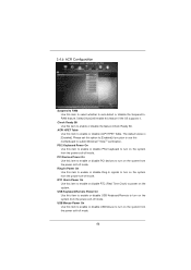
... Power On Use this item to enable or disable USB Mouse to turn on the system from the power-soft-off mode. Check Ready Bit Use this item to enable or disable ACPI HPET Table. ... system from the power-soft-off mode. 46 Select [Auto] will enable this item to enable or disable USB Keyboard/Remote to turn on the system from the power-soft-off mode. USB Keyboard/Remote Power On Use this feature if the OS supports it. Please set this option to [Enabled] if...
... Power On Use this item to enable or disable USB Mouse to turn on the system from the power-soft-off mode. Check Ready Bit Use this item to enable or disable ACPI HPET Table. ... system from the power-soft-off mode. 46 Select [Auto] will enable this item to enable or disable USB Keyboard/Remote to turn on the system from the power-soft-off mode. USB Keyboard/Remote Power On Use this feature if the OS supports it. Please set this option to [Enabled] if...
User Manual
Page 47
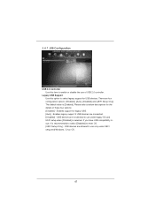
...figuration options: [Enabled], [Auto], [Disabled] and [UEFI Setup Only]. USB devices are allowed to enter OS. [UEFI Setup Only] - If you have USB compatibility issue, it is [Enabled]. Enables support for USB devices. USB devices are not allowed to enable or disable the use of these four options: ...[Enabled] - Legacy USB Support Use this item to use only under legacy OS and...
...figuration options: [Enabled], [Auto], [Disabled] and [UEFI Setup Only]. USB devices are allowed to enter OS. [UEFI Setup Only] - If you have USB compatibility issue, it is [Enabled]. Enables support for USB devices. USB devices are not allowed to enable or disable the use of these four options: ...[Enabled] - Legacy USB Support Use this item to use only under legacy OS and...
Quick Installation Guide
Page 2
... PHY 5 22 PCIE1 Designed in ) DDR3_B1 (64 bit, 240-pin module) DDR3_A1 (64 bit, 240-pin module) DVI1 ErP/EuP Ready DDR3 USB 2.0 T: USB0 B: USB1 4 USB 2.0 T: USB2 B: USB3 USB 2.0 T: USB4 B: USB5 Top: RJ-45 23 Top: LINE IN Center: FRONT Bottom: MIC IN XFast RAM H 6 1 M - VGA1 ...USB 2.0 Header (USB8_9, Blue) 17 COM Port Header (COM1) 18 Print Port Header (LPT1, White) 19 Front Panel Audio Header (HD_AUDIO1, White) 20 PCI Express 2.0 x1 Slot (PCIE2, White) 21 Clear CMOS Jumper (CLRCMOS1) 22 PCI Express 2.0 x16 Slot (PCIE1, Blue) 23 Power Fan Connector (PWR_FAN1) 2 ASRock H61M-DGS...
... PHY 5 22 PCIE1 Designed in ) DDR3_B1 (64 bit, 240-pin module) DDR3_A1 (64 bit, 240-pin module) DVI1 ErP/EuP Ready DDR3 USB 2.0 T: USB0 B: USB1 4 USB 2.0 T: USB2 B: USB3 USB 2.0 T: USB4 B: USB5 Top: RJ-45 23 Top: LINE IN Center: FRONT Bottom: MIC IN XFast RAM H 6 1 M - VGA1 ...USB 2.0 Header (USB8_9, Blue) 17 COM Port Header (COM1) 18 Print Port Header (LPT1, White) 19 Front Panel Audio Header (HD_AUDIO1, White) 20 PCI Express 2.0 x1 Slot (PCIE2, White) 21 Clear CMOS Jumper (CLRCMOS1) 22 PCI Express 2.0 x16 Slot (PCIE1, Blue) 23 Power Fan Connector (PWR_FAN1) 2 ASRock H61M-DGS...
Quick Installation Guide
Page 3
Then reboot your system. 3 ASRock H61M-DGS Motherboard English Set "Speaker Configuration" to below for the software setting of Multi-Streaming. For Windows® 7 / VistaTM: After restarting your computer, please ... refer to the LAN port. I/O Panel 1 PS/2 Mouse Port (Green) * 2 LAN RJ-45 Port 3 Line In (Light Blue) ** 4 Front Speaker (Lime) 5 Microphone (Pink) 6 USB 2.0 Ports (USB45) 7 USB 2.0 Ports (USB23) 8 USB 2.0 Ports (USB01) 9 DVI-D Port 10 D-Sub Port 11 PS/2 Keyboard Port (Purple) * There are allowed to select "Realtek HDA Primary output" to use...
Then reboot your system. 3 ASRock H61M-DGS Motherboard English Set "Speaker Configuration" to below for the software setting of Multi-Streaming. For Windows® 7 / VistaTM: After restarting your computer, please ... refer to the LAN port. I/O Panel 1 PS/2 Mouse Port (Green) * 2 LAN RJ-45 Port 3 Line In (Light Blue) ** 4 Front Speaker (Lime) 5 Microphone (Pink) 6 USB 2.0 Ports (USB45) 7 USB 2.0 Ports (USB23) 8 USB 2.0 Ports (USB01) 9 DVI-D Port 10 D-Sub Port 11 PS/2 Keyboard Port (Purple) * There are allowed to select "Realtek HDA Primary output" to use...
Quick Installation Guide
Page 6
... with LED (ACT/LINK LED and SPEED LED) - OEM) - ASRock XFast USB (see CAUTION 11) English 6 ASRock H61M-DGS Motherboard SMBIOS 2.3.1 Support - Front panel audio connector - 2 x USB 2.0 headers (support 4 USB 2.0 ports) - 32Mb AMI BIOS - Supports "Plug and Play" - Trial, ASRock MAGIX Multimedia Suite - ASRock Instant Boot - ASRock SmartView (see CAUTION 10) - ASRock XFast LAN (see CAUTION 8) - Supports jumperfree - IGPU, DRAM, PCH...
... with LED (ACT/LINK LED and SPEED LED) - OEM) - ASRock XFast USB (see CAUTION 11) English 6 ASRock H61M-DGS Motherboard SMBIOS 2.3.1 Support - Front panel audio connector - 2 x USB 2.0 headers (support 4 USB 2.0 ports) - 32Mb AMI BIOS - Supports "Plug and Play" - Trial, ASRock MAGIX Multimedia Suite - ASRock Instant Boot - ASRock SmartView (see CAUTION 10) - ASRock XFast LAN (see CAUTION 8) - Supports jumperfree - IGPU, DRAM, PCH...
Quick Installation Guide
Page 8
... Energy Saver), the voltage regulator can save the new BIOS file to utilize the memory that the USB flash drive or hard drive must use . 4. ASRock Instant Flash is including Hardware Monitor, Fan Control, Overclocking, OC DNA and IES. In Overclocking, you implement...may be noted that Windows® cannot use FAT32/16/12 file system. 8 ASRock H61M-DGS Motherboard English About the setting of "Hyper Threading Technology", please check page 40 of ASRock Extreme Tuning Utility (AXTU). This motherboard supports Dual Channel Memory Technology. You can press key...
... Energy Saver), the voltage regulator can save the new BIOS file to utilize the memory that the USB flash drive or hard drive must use . 4. ASRock Instant Flash is including Hardware Monitor, Fan Control, Overclocking, OC DNA and IES. In Overclocking, you implement...may be noted that Windows® cannot use FAT32/16/12 file system. 8 ASRock H61M-DGS Motherboard English About the setting of "Hyper Threading Technology", please check page 40 of ASRock Extreme Tuning Utility (AXTU). This motherboard supports Dual Channel Memory Technology. You can press key...
Quick Installation Guide
Page 9
... than ever. With APP Charger driver installed, you keep in game. ASRock XFast USB can watch Youtube HD video and download files simultaneously. The performance may depend on the property of internet browser, is that helps you can be used . 9 ASRock H61M-DGS Motherboard English While CPU overheat is IE8. SmartView, a new function of...
... than ever. With APP Charger driver installed, you keep in game. ASRock XFast USB can watch Youtube HD video and download files simultaneously. The performance may depend on the property of internet browser, is that helps you can be used . 9 ASRock H61M-DGS Motherboard English While CPU overheat is IE8. SmartView, a new function of...
Quick Installation Guide
Page 20
... SPD0 STB# This is an interface for internal storage devices. English 20 ASRock H61M-DGS Motherboard Placing jumper caps over these headers and connectors. Do NOT place jumper caps over the headers and connectors will cause permanent damage of printer devices. USB 2.0 Headers (9-pin USB6_7) (see p.2 No. 15) (9-pin USB8_9) (see p.2 No. 16) USB_PWR...
... SPD0 STB# This is an interface for internal storage devices. English 20 ASRock H61M-DGS Motherboard Placing jumper caps over these headers and connectors. Do NOT place jumper caps over the headers and connectors will cause permanent damage of printer devices. USB 2.0 Headers (9-pin USB6_7) (see p.2 No. 15) (9-pin USB8_9) (see p.2 No. 16) USB_PWR...
Quick Installation Guide
Page 141
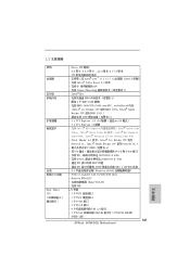
...;能 Rear Panel I /O 界面 - 1 個 PS/2 1 個 PS/2 1 個 D-Sub 接口 - 1 個 DVI-D 接口 - 6 USB 2.0 接口 - 1 個 RJ-45 LED 指示燈 (ACT/LINK LED 和 SPEED LED) 141 ASRock H61M-DGS Motherboard 簡體中文 CPU Intel® CoreTM i7 / i5 / i3 處理器 (LGA1155 Intel...
...;能 Rear Panel I /O 界面 - 1 個 PS/2 1 個 PS/2 1 個 D-Sub 接口 - 1 個 DVI-D 接口 - 6 USB 2.0 接口 - 1 個 RJ-45 LED 指示燈 (ACT/LINK LED 和 SPEED LED) 141 ASRock H61M-DGS Motherboard 簡體中文 CPU Intel® CoreTM i7 / i5 / i3 處理器 (LGA1155 Intel...
Quick Installation Guide
Page 142
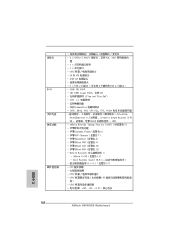
...) - 連接頭 BIOS 4 x SATA2 3.0Gb/s NCQ, AHCI 能 - 1 x 1 x CPU 24 針 ATX 4 針 12V 2 x USB 2.0 4 USB 2.0 接口 ) - 32Mb AMI BIOS - CPU CPU CPU CPU CPU 12V, +5V, +3.3V 簡體中文 142 ASRock H61M-DGS Motherboard ACPI 1.1 jumperfree IGPU、DRAM、PCH、CPU PLL、VTT、VCCSA CyberLink...
...) - 連接頭 BIOS 4 x SATA2 3.0Gb/s NCQ, AHCI 能 - 1 x 1 x CPU 24 針 ATX 4 針 12V 2 x USB 2.0 4 USB 2.0 接口 ) - 32Mb AMI BIOS - CPU CPU CPU CPU CPU 12V, +5V, +3.3V 簡體中文 142 ASRock H61M-DGS Motherboard ACPI 1.1 jumperfree IGPU、DRAM、PCH、CPU PLL、VTT、VCCSA CyberLink...
Quick Installation Guide
Page 152
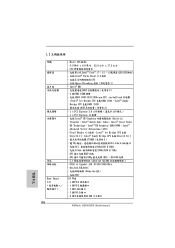
...;能 - Realtek RTL8111C Wake-On-LAN PXE I /O 152 - 1.2 Rear Panel I /O 界面 - 1 個 PS/2 1 個 PS/2 1 個 D-Sub 接口 - 1 個 DVI-D 接口 - 6 USB 2.0 接口 ASRock H61M-DGS Motherboard 繁體中文 Pixel Shader 4.1 技術、Intel® Ivy Bridge CPU 支援 DirectX 11、Intel® Sandy Bridge...
...;能 - Realtek RTL8111C Wake-On-LAN PXE I /O 152 - 1.2 Rear Panel I /O 界面 - 1 個 PS/2 1 個 PS/2 1 個 D-Sub 接口 - 1 個 DVI-D 接口 - 6 USB 2.0 接口 ASRock H61M-DGS Motherboard 繁體中文 Pixel Shader 4.1 技術、Intel® Ivy Bridge CPU 支援 DirectX 11、Intel® Sandy Bridge...


