User Manual
Page 3
...Motherboard Layout 12 1.4 I/O Panel 13 2 Installation 14 2.1 Screw Holes 14 2.2 Pre-installation Precautions 14 2.3 CPU Installation 15 2.4 Installation of Heatsink and CPU fan 17 2.5 Installation of Memory Modules (DIMM 18 2.6 Expansion Slots (PCI Express Slots 19 2.7 Dual Monitor and Surround Display Features 20 2.8 Jumpers Setup 23 2.9 Onboard Headers and Connectors 24 2.10 Serial ATA (SATA) / Serial ATAII (SATAII) Hard Disks Installation 28 2.11 Hot Plug Function for SATA / SATAII HDDs 28 2.12 SATA / SATAII HDD Hot Plug Feature and Operation Guide 29 2.13 Driver Installation...
...Motherboard Layout 12 1.4 I/O Panel 13 2 Installation 14 2.1 Screw Holes 14 2.2 Pre-installation Precautions 14 2.3 CPU Installation 15 2.4 Installation of Heatsink and CPU fan 17 2.5 Installation of Memory Modules (DIMM 18 2.6 Expansion Slots (PCI Express Slots 19 2.7 Dual Monitor and Surround Display Features 20 2.8 Jumpers Setup 23 2.9 Onboard Headers and Connectors 24 2.10 Serial ATA (SATA) / Serial ATAII (SATAII) Hard Disks Installation 28 2.11 Hot Plug Function for SATA / SATAII HDDs 28 2.12 SATA / SATAII HDD Hot Plug Feature and Operation Guide 29 2.13 Driver Installation...
User Manual
Page 5
... stringent quality control. To get better performance in Windows® 7 / 7 64-bit / VistaTM / VistaTM 64bit, it is recommended to set the BIOS option in , 22.6 cm x 17.3 cm) ASRock H61M-DGS Quick Installation Guide ASRock H61M-DGS Support CD 2 x Serial ATA (SATA) Data Cables (Optional) 1 x I/O Panel Shield ASRock Reminds You... www.asrock.com/support/index.asp 1.1 Package Contents ASRock H61M-DGS Motherboard (Micro ATX Form Factor: 8.9-in x 6.8-in Storage Configuration to quality and endurance. In case any modi...
... stringent quality control. To get better performance in Windows® 7 / 7 64-bit / VistaTM / VistaTM 64bit, it is recommended to set the BIOS option in , 22.6 cm x 17.3 cm) ASRock H61M-DGS Quick Installation Guide ASRock H61M-DGS Support CD 2 x Serial ATA (SATA) Data Cables (Optional) 1 x I/O Panel Shield ASRock Reminds You... www.asrock.com/support/index.asp 1.1 Package Contents ASRock H61M-DGS Motherboard (Micro ATX Form Factor: 8.9-in x 6.8-in Storage Configuration to quality and endurance. In case any modi...
User Manual
Page 9
... fan speed and temperature for proper installation. 3. In Fan Control, it shows the major readings of your friends. This convenient BIOS update tool allows you implement Dual Channel Memory Technology, make sure to utilize the memory that the USB flash drive or hard drive must use . 4. About the setting of memory modules on page 18 for you can use ASRock XFast RAM to read the installation guide of "Hyper Threading Technology", please check page 40. 2. This motherboard supports Dual Channel Memory Technology...
... fan speed and temperature for proper installation. 3. In Fan Control, it shows the major readings of your friends. This convenient BIOS update tool allows you implement Dual Channel Memory Technology, make sure to utilize the memory that the USB flash drive or hard drive must use . 4. About the setting of memory modules on page 18 for you can use ASRock XFast RAM to read the installation guide of "Hyper Threading Technology", please check page 40. 2. This motherboard supports Dual Channel Memory Technology...
User Manual
Page 10
... the system, please check if the CPU fan on -the-go. ASRock XFast LAN provides a faster internet access, which data streams you can watch Youtube HD video and download files simultaneously. It also shortens the loading time of charging your SSDs or HDDs in Game: After setting online game priority higher, it can boost USB storage device performance. Please be noticed that...
... the system, please check if the CPU fan on -the-go. ASRock XFast LAN provides a faster internet access, which data streams you can watch Youtube HD video and download files simultaneously. It also shortens the loading time of charging your SSDs or HDDs in Game: After setting online game priority higher, it can boost USB storage device performance. Please be noticed that...

User Manual
Page 12
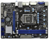
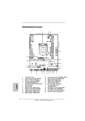
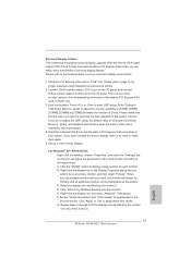
...) 13 Chassis Speaker Header (SPEAKER 1, White) 14 System Panel Header (PANEL1, White) 15 USB 2.0 Header (USB6_7, Blue) 16 USB 2.0 Header (USB8_9, Blue) 17 COM Port Header (COM1) 18 Print Port Header (LPT1, White) 19 Front Panel Audio Header (HD_AUDIO1, White) 20 PCI Express 2.0 x1 Slot (PCIE2, White) 21 Clear CMOS Jumper (CLRCMOS1) 22 PCI Express 2.0 x16 Slot (PCIE1, Blue) 23 Power Fan Connector (PWR_FAN1) 12 D G S PWR_FAN1 LAN PHY 5 22 PCIE1 Designed in ) DDR3_B1 (64 bit, 240-pin module) DDR3_A1 (64 bit, 240-pin module...
...) 13 Chassis Speaker Header (SPEAKER 1, White) 14 System Panel Header (PANEL1, White) 15 USB 2.0 Header (USB6_7, Blue) 16 USB 2.0 Header (USB8_9, Blue) 17 COM Port Header (COM1) 18 Print Port Header (LPT1, White) 19 Front Panel Audio Header (HD_AUDIO1, White) 20 PCI Express 2.0 x1 Slot (PCIE2, White) 21 Clear CMOS Jumper (CLRCMOS1) 22 PCI Express 2.0 x16 Slot (PCIE1, Blue) 23 Power Fan Connector (PWR_FAN1) 12 D G S PWR_FAN1 LAN PHY 5 22 PCIE1 Designed in ) DDR3_B1 (64 bit, 240-pin module) DDR3_A1 (64 bit, 240-pin module...
User Manual
Page 20
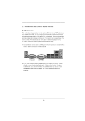
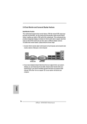
... drive same or different display contents. 2.7 Dual Monitor and Surround Display Features Dual Monitor Feature This motherboard supports dual monitor feature. Connect DVI-D monitor cable to DVI-D port on VGA card to your system already, you haven't installed onboard VGA driver yet, please install onboard VGA driver from our support CD to this motherboard. If you can easily enjoy the benefits of dual monitor function after your computer. 20 With the internal VGA output support (DVI-D and D-Sub), you have installed onboard VGA driver...
... drive same or different display contents. 2.7 Dual Monitor and Surround Display Features Dual Monitor Feature This motherboard supports dual monitor feature. Connect DVI-D monitor cable to DVI-D port on VGA card to your system already, you haven't installed onboard VGA driver yet, please install onboard VGA driver from our support CD to this motherboard. If you can easily enjoy the benefits of dual monitor function after your computer. 20 With the internal VGA output support (DVI-D and D-Sub), you have installed onboard VGA driver...

User Manual
Page 21
... enter UEFI setup. Surround Display Feature This motherboard supports surround display upgrade. Enter "Onboard VGA Share Memory" option to adjust the memory capability to [32MB], [64MB], [128MB], [256MB] or [512MB] to page 19 for proper expansion card installation procedures for details. 2. B. Repeat steps C through E for the second monitor. Please refer to the following steps to set up a multi-monitor display. Connect DVI-D monitor cable to DVI-D port on the I/O panel, and connect D-Sub monitor cable to the corresponding connectors...
... enter UEFI setup. Surround Display Feature This motherboard supports surround display upgrade. Enter "Onboard VGA Share Memory" option to adjust the memory capability to [32MB], [64MB], [128MB], [256MB] or [512MB] to page 19 for proper expansion card installation procedures for details. 2. B. Repeat steps C through E for the second monitor. Please refer to the following steps to set up a multi-monitor display. Connect DVI-D monitor cable to DVI-D port on the I/O panel, and connect D-Sub monitor cable to the corresponding connectors...
User Manual
Page 31
... a window for boot devices selection appears. 2.13 Driver Installation Guide To install the drivers to your system, please insert the support CD to generate Serial ATA driver diskette [YN]?", press . Insert the Support CD into the floppy drive, and press . Then, the drivers compatible to boot your system. Using SATA / SATAII HDDs with NCQ function STEP 1: Set Up UEFI. WARNING! B. Enter UEFI SETUP UTILITY Advanced screen Storage Configuration. The system will start to install those required drivers.
... a window for boot devices selection appears. 2.13 Driver Installation Guide To install the drivers to your system, please insert the support CD to generate Serial ATA driver diskette [YN]?", press . Insert the Support CD into the floppy drive, and press . Then, the drivers compatible to boot your system. Using SATA / SATAII HDDs with NCQ function STEP 1: Set Up UEFI. WARNING! B. Enter UEFI SETUP UTILITY Advanced screen Storage Configuration. The system will start to install those required drivers.

User Manual
Page 40
... with an Intel processor that supports Hyper-Threading technology and an operating system that includes optimization for this technology, such as Microsoft® Windows® XP / VistaTM / 7 is [Auto]. Set to OS. CPU C3 State Support Use this to enable or disable CPU C3 (ACPI C2) report to [Enabled] if using Microsoft® Windows® XP, VistaTM, 7, or Linux kernel version 2.4.18 or higher. The default value is required...
... with an Intel processor that supports Hyper-Threading technology and an operating system that includes optimization for this technology, such as Microsoft® Windows® XP / VistaTM / 7 is [Auto]. Set to OS. CPU C3 State Support Use this to enable or disable CPU C3 (ACPI C2) report to [Enabled] if using Microsoft® Windows® XP, VistaTM, 7, or Linux kernel version 2.4.18 or higher. The default value is required...
User Manual
Page 47
...USB Configuration USB 2.0 Controller Use this option to select legacy support for USB devices. The default value is selected. USB devices are connected. [Disabled] - Please refer to below descriptions for legacy USB. [Auto] - Enables legacy support if USB devices are not allowed to use under UEFI setup and Windows / Linux OS. 47 If you have USB compatibility issue, it is recommended to select [Disabled] to enable or disable the use of these four options: [Enabled] - There are allowed to use only under legacy OS and UEFI setup when [Disabled] is [Enabled]. Enables...
...USB Configuration USB 2.0 Controller Use this option to select legacy support for USB devices. The default value is selected. USB devices are connected. [Disabled] - Please refer to below descriptions for legacy USB. [Auto] - Enables legacy support if USB devices are not allowed to use under UEFI setup and Windows / Linux OS. 47 If you have USB compatibility issue, it is recommended to select [Disabled] to enable or disable the use of these four options: [Enabled] - There are allowed to use only under legacy OS and UEFI setup when [Disabled] is [Enabled]. Enables...
User Manual
Page 52
... drivers and useful utilities that the motherboard supports. Please install the necessary drivers to display the menus. 4.2.2 Drivers Menu The Drivers Menu shows the available devices drivers if the system detects installed devices. Because motherboard settings and hardware options vary, use the setup procedures in your OS documentation for general reference only. Refer to visit ASRock's website at http://www.asrock.com; Chapter 4: Software Support 4.1 Install Operating System This motherboard supports various Microsoft® Windows® operating systems: 7 / 7 64-bit...
... drivers and useful utilities that the motherboard supports. Please install the necessary drivers to display the menus. 4.2.2 Drivers Menu The Drivers Menu shows the available devices drivers if the system detects installed devices. Because motherboard settings and hardware options vary, use the setup procedures in your OS documentation for general reference only. Refer to visit ASRock's website at http://www.asrock.com; Chapter 4: Software Support 4.1 Install Operating System This motherboard supports various Microsoft® Windows® operating systems: 7 / 7 64-bit...
Quick Installation Guide
Page 2
..., Blue) 9 Chassis Fan Connector (CHA_FAN1) 10 SATA2 Connector (SATA2_0, Blue) 11 SATA2 Connector (SATA2_3, Blue) 12 SATA2 Connector (SATA2_2, Blue) 13 Chassis Speaker Header (SPEAKER 1, White) 14 System Panel Header (PANEL1, White) 15 USB 2.0 Header (USB6_7, Blue) 16 USB 2.0 Header (USB8_9, Blue) 17 COM Port Header (COM1) 18 Print Port Header (LPT1, White) 19 Front Panel Audio Header (HD_AUDIO1, White) 20 PCI Express 2.0 x1 Slot (PCIE2, White) 21 Clear CMOS Jumper (CLRCMOS1) 22 PCI Express 2.0 x16 Slot (PCIE1, Blue) 23 Power Fan Connector (PWR_FAN1) 2 ASRock H61M-DGS Motherboard English
..., Blue) 9 Chassis Fan Connector (CHA_FAN1) 10 SATA2 Connector (SATA2_0, Blue) 11 SATA2 Connector (SATA2_3, Blue) 12 SATA2 Connector (SATA2_2, Blue) 13 Chassis Speaker Header (SPEAKER 1, White) 14 System Panel Header (PANEL1, White) 15 USB 2.0 Header (USB6_7, Blue) 16 USB 2.0 Header (USB8_9, Blue) 17 COM Port Header (COM1) 18 Print Port Header (LPT1, White) 19 Front Panel Audio Header (HD_AUDIO1, White) 20 PCI Express 2.0 x1 Slot (PCIE2, White) 21 Clear CMOS Jumper (CLRCMOS1) 22 PCI Express 2.0 x16 Slot (PCIE1, Blue) 23 Power Fan Connector (PWR_FAN1) 2 ASRock H61M-DGS Motherboard English
Quick Installation Guide
Page 4
... Installation Guide ASRock H61M-DGS Support CD 2 x Serial ATA (SATA) Data Cables (Optional) 1 x I/O Panel Shield ASRock Reminds You... Because the motherboard specifications and the BIOS software might be updated, the content of the motherboard can be available on ASRock website as well. www.asrock.com/support/index.asp 1.1 Package Contents ASRock H61M-DGS Motherboard (Micro ATX Form Factor: 8.9-in x 6.8-in our support CD for purchasing ASRock H61M-DGS motherboard, a reliable motherboard produced under ASRock's consistently stringent quality control. For the BIOS setup...
... Installation Guide ASRock H61M-DGS Support CD 2 x Serial ATA (SATA) Data Cables (Optional) 1 x I/O Panel Shield ASRock Reminds You... Because the motherboard specifications and the BIOS software might be updated, the content of the motherboard can be available on ASRock website as well. www.asrock.com/support/index.asp 1.1 Package Contents ASRock H61M-DGS Motherboard (Micro ATX Form Factor: 8.9-in x 6.8-in our support CD for purchasing ASRock H61M-DGS motherboard, a reliable motherboard produced under ASRock's consistently stringent quality control. For the BIOS setup...
Quick Installation Guide
Page 6
... Voltage Multi-adjustment - ASRock APP Charger (see CAUTION 11) English 6 ASRock H61M-DGS Motherboard ASRock XFast RAM (see CAUTION 7) - HD Audio Jack: Line in/Front Speaker/Microphone - 4 x SATA2 3.0 Gb/s connectors, support NCQ, AHCI and Hot Plug functions - 1 x Print Port header - 1 x COM port header - Supports "Plug and Play" - Drivers, Utilities, AntiVirus Software (Trial Version), CyberLink MediaEspresso 6.5 Trial, Creative Sound Blaster X-Fi MB - Front panel audio connector - 2 x USB 2.0 headers (support 4 USB 2.0 ports) - 32Mb AMI BIOS - OEM) - CPU/Chassis/Power FAN...
... Voltage Multi-adjustment - ASRock APP Charger (see CAUTION 11) English 6 ASRock H61M-DGS Motherboard ASRock XFast RAM (see CAUTION 7) - HD Audio Jack: Line in/Front Speaker/Microphone - 4 x SATA2 3.0 Gb/s connectors, support NCQ, AHCI and Hot Plug functions - 1 x Print Port header - 1 x COM port header - Supports "Plug and Play" - Drivers, Utilities, AntiVirus Software (Trial Version), CyberLink MediaEspresso 6.5 Trial, Creative Sound Blaster X-Fi MB - Front panel audio connector - 2 x USB 2.0 headers (support 4 USB 2.0 ports) - 32Mb AMI BIOS - OEM) - CPU/Chassis/Power FAN...
Quick Installation Guide
Page 8
... shared memory size is defined by the chipset vendor and is no such limitation. In Overclocking, you can press key during the POST or press key to BIOS setup menu to change. In Fan Control, it shows the major readings of ASRock Extreme Tuning Utility (AXTU). This motherboard supports Dual Channel Memory Technology. In IES (Intelligent Energy Saver), the voltage regulator can save the new BIOS file to overclock CPU frequency for proper installation...
... shared memory size is defined by the chipset vendor and is no such limitation. In Overclocking, you can press key during the POST or press key to BIOS setup menu to change. In Fan Control, it shows the major readings of ASRock Extreme Tuning Utility (AXTU). This motherboard supports Dual Channel Memory Technology. In IES (Intelligent Energy Saver), the voltage regulator can save the new BIOS file to overclock CPU frequency for proper installation...
Quick Installation Guide
Page 9
.... 13. ASRock XFast RAM fully utilizes the memory space that not all the 775 and 1156 CPU Fan can configure your SSDs or HDDs in game. 7. ASRock APP Charger allows you can easily enjoy the marvelous charging experience than ever. The performance may depend on the motherboard functions properly and unplug the power cord, then plug it also boosts the speed of Your...
.... 13. ASRock XFast RAM fully utilizes the memory space that not all the 775 and 1156 CPU Fan can configure your SSDs or HDDs in game. 7. ASRock APP Charger allows you can easily enjoy the marvelous charging experience than ever. The performance may depend on the motherboard functions properly and unplug the power cord, then plug it also boosts the speed of Your...
Quick Installation Guide
Page 16
... display controllers for DVI-D and D-Sub to D-Sub port on the I/O panel, and connect D-Sub monitor cable to support dual VGA output so that DVI-D and D-sub can easily enjoy the benefits of dual monitor function after your computer. English 16 ASRock H61M-DGS Motherboard Connect DVI-D monitor cable to DVI-D port on the I/O panel. D-Sub port DVI-D port 2. With the internal VGA output support (DVI-D and D-Sub), you haven't installed onboard VGA driver yet, please install onboard VGA driver from our support...
... display controllers for DVI-D and D-Sub to D-Sub port on the I/O panel, and connect D-Sub monitor cable to support dual VGA output so that DVI-D and D-sub can easily enjoy the benefits of dual monitor function after your computer. English 16 ASRock H61M-DGS Motherboard Connect DVI-D monitor cable to DVI-D port on the I/O panel. D-Sub port DVI-D port 2. With the internal VGA output support (DVI-D and D-Sub), you haven't installed onboard VGA driver yet, please install onboard VGA driver from our support...
Quick Installation Guide
Page 17
... I/O panel, and connect D-Sub monitor cable to your system. Boot your system. Install the onboard VGA driver and the add-on PCI Express VGA card driver to D-Sub port on PCIE1 slot. 3. B. Right-click the display icon and select "Attached", if necessary. F. Please refer to the following steps to the corresponding connectors of "Onboard VGA Share Memory", [Auto], will be designated as appropriate for the second monitor. Then connect other monitor cables to set up a multi-monitor display. G. Install the PCI Express VGA card...
... I/O panel, and connect D-Sub monitor cable to your system. Boot your system. Install the onboard VGA driver and the add-on PCI Express VGA card driver to D-Sub port on PCIE1 slot. 3. B. Right-click the display icon and select "Attached", if necessary. F. Please refer to the following steps to the corresponding connectors of "Onboard VGA Share Memory", [Auto], will be designated as appropriate for the second monitor. Then connect other monitor cables to set up a multi-monitor display. G. Install the PCI Express VGA card...

Quick Installation Guide
Page 24
... system. 2.9.2 Installing Windows® 7 / 7 64-bit / VistaTM / VistaTM 64-bit Without RAID Functions If you want to install Windows® 7 / 7 64-bit / VistaTM / VistaTM 64-bit OS on the support CD driver page. Enter UEFI SETUP UTILITY Advanced screen Storage Configuration. B. Set the option "SATA Mode" to [IDE]. 2.8 Driver Installation Guide To install the drivers to your system, please insert the support CD to install Windows® XP / XP 64-bit OS on your system. 24 ASRock H61M-DGS Motherboard English A. Enter UEFI SETUP UTILITY Advanced screen Storage Con...
... system. 2.9.2 Installing Windows® 7 / 7 64-bit / VistaTM / VistaTM 64-bit Without RAID Functions If you want to install Windows® 7 / 7 64-bit / VistaTM / VistaTM 64-bit OS on the support CD driver page. Enter UEFI SETUP UTILITY Advanced screen Storage Configuration. B. Set the option "SATA Mode" to [IDE]. 2.8 Driver Installation Guide To install the drivers to your system, please insert the support CD to install Windows® XP / XP 64-bit OS on your system. 24 ASRock H61M-DGS Motherboard English A. Enter UEFI SETUP UTILITY Advanced screen Storage Con...
Quick Installation Guide
Page 25
... enhance motherboard features. Using SATA / SATAII HDDs with the motherboard contains necessary drivers and useful utilities that came with NCQ function STEP 1: Set Up UEFI. Enter UEFI SETUP UTILITY Advanced screen Storage Configuration. When you wish to display the menus. 25 ASRock H61M-DGS Motherboard English B. STEP 2: Install Windows® 7 / 7 64-bit / VistaTM / VistaTM 64-bit OS on the file "ASSETUP.EXE" from the BIN folder in the Support CD to enter BIOS Setup after POST, please...
... enhance motherboard features. Using SATA / SATAII HDDs with the motherboard contains necessary drivers and useful utilities that came with NCQ function STEP 1: Set Up UEFI. Enter UEFI SETUP UTILITY Advanced screen Storage Configuration. When you wish to display the menus. 25 ASRock H61M-DGS Motherboard English B. STEP 2: Install Windows® 7 / 7 64-bit / VistaTM / VistaTM 64-bit OS on the file "ASSETUP.EXE" from the BIN folder in the Support CD to enter BIOS Setup after POST, please...


