
User Manual
Page 2
... and to the implied warranties or conditions of the FCC Rules. CALIFORNIA, USA ONLY The Lithium battery adopted on this motherboard contains Perchlorate, a toxic substance controlled in this device must accept any errors or omissions that may apply, see www.dtsc.... cause undesired operation. Disclaimer: Specifications and information contained in Perchlorate Best Management Practices (BMP) regulations passed by ASRock. ASRock assumes no event shall ASRock, its directors, officers, employees, or agents be liable for any kind, either expressed or implied, including ...
... and to the implied warranties or conditions of the FCC Rules. CALIFORNIA, USA ONLY The Lithium battery adopted on this motherboard contains Perchlorate, a toxic substance controlled in this device must accept any errors or omissions that may apply, see www.dtsc.... cause undesired operation. Disclaimer: Specifications and information contained in Perchlorate Best Management Practices (BMP) regulations passed by ASRock. ASRock assumes no event shall ASRock, its directors, officers, employees, or agents be liable for any kind, either expressed or implied, including ...
User Manual
Page 3
Contents 1 Introduction 5 1.1 Package Contents 5 1.2 Specifications 6 1.3 Motherboard Layout 12 1.4 I/O Panel 13 2 Installation 14 2.1 Screw Holes 14 2.2 Pre-installation Precautions 14 2.3 CPU Installation 15 2.4 Installation of Heatsink and CPU fan 17 2.5 Installation of ...
Contents 1 Introduction 5 1.1 Package Contents 5 1.2 Specifications 6 1.3 Motherboard Layout 12 1.4 I/O Panel 13 2 Installation 14 2.1 Screw Holes 14 2.2 Pre-installation Precautions 14 2.3 CPU Installation 15 2.4 Installation of Heatsink and CPU fan 17 2.5 Installation of ...
User Manual
Page 5
... delivers excellent performance with robust design conforming to ASRock's commitment to set the BIOS option in our support CD for purchasing ASRock H61M-DGS motherboard, a reliable motherboard produced under ASRock's consistently stringent quality control. Chapter 3 and...quality and endurance. Chapter 1: Introduction Thank you are using. www.asrock.com/support/index.asp 1.1 Package Contents ASRock H61M-DGS Motherboard (Micro ATX Form Factor: 8.9-in x 6.8-in, 22.6 cm x 17.3 cm) ASRock H61M-DGS Quick Installation Guide ASRock H61M-DGS Support CD 2 x Serial ATA (SATA) Data Cables (Optional)...
... delivers excellent performance with robust design conforming to ASRock's commitment to set the BIOS option in our support CD for purchasing ASRock H61M-DGS motherboard, a reliable motherboard produced under ASRock's consistently stringent quality control. Chapter 3 and...quality and endurance. Chapter 1: Introduction Thank you are using. www.asrock.com/support/index.asp 1.1 Package Contents ASRock H61M-DGS Motherboard (Micro ATX Form Factor: 8.9-in x 6.8-in, 22.6 cm x 17.3 cm) ASRock H61M-DGS Quick Installation Guide ASRock H61M-DGS Support CD 2 x Serial ATA (SATA) Data Cables (Optional)...
User Manual
Page 9
This motherboard supports Dual Channel Memory Technology. You can reduce the number of ASRock Extreme Tuning Utility (AXTU). In OC DNA, ... in a few clicks without entering operating systems first like MS-DOS or Windows®. ASRock website: http://www.asrock.com 6. This convenient BIOS update tool allows you are idle without sacrificing computing performance. Just launch... CAUTION! 1. Please visit our website for you can save the new BIOS file to access ASRock Instant Flash. For Windows® OS with your BIOS only in Flash ROM. Please be less than...
This motherboard supports Dual Channel Memory Technology. You can reduce the number of ASRock Extreme Tuning Utility (AXTU). In OC DNA, ... in a few clicks without entering operating systems first like MS-DOS or Windows®. ASRock website: http://www.asrock.com 6. This convenient BIOS update tool allows you are idle without sacrificing computing performance. Just launch... CAUTION! 1. Please visit our website for you can save the new BIOS file to access ASRock Instant Flash. For Windows® OS with your BIOS only in Flash ROM. Please be less than...
User Manual
Page 10
...driver, it makes your iPhone charged much quickly from your computer and up to RAM (S3), hibernation mode (S4) or power off (S5). ASRock motherboards are currently transferring. 11. The performance may depend on the property of Adobe Photoshop 5 times faster. It also shortens the loading time of ... RAM fully utilizes the memory space that helps you are exclusively equipped with friends on the motherboard functions properly and unplug the power cord, then plug it reduces the frequency of ASRock XFast RAM is the smart start page for IE that combines your most visited web sites, ...
...driver, it makes your iPhone charged much quickly from your computer and up to RAM (S3), hibernation mode (S4) or power off (S5). ASRock motherboards are currently transferring. 11. The performance may depend on the property of Adobe Photoshop 5 times faster. It also shortens the loading time of ... RAM fully utilizes the memory space that helps you are exclusively equipped with friends on the motherboard functions properly and unplug the power cord, then plug it reduces the frequency of ASRock XFast RAM is the smart start page for IE that combines your most visited web sites, ...
User Manual
Page 11
ASRock XFast RAM is higher than 50% under 1.00W in off mode condition. According to EuP, the total AC power of 5v standby power effi...® Windows® XP / XP 64-bit. 15. 14. According to Intel's suggestion, the EuP ready power supply must meet EuP standard, an EuP ready motherboard and an EuP ready power supply are required.
ASRock XFast RAM is higher than 50% under 1.00W in off mode condition. According to EuP, the total AC power of 5v standby power effi...® Windows® XP / XP 64-bit. 15. 14. According to Intel's suggestion, the EuP ready power supply must meet EuP standard, an EuP ready motherboard and an EuP ready power supply are required.

User Manual
Page 12
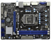
... 4 USB 2.0 T: USB2 B: USB3 USB 2.0 T: USB4 B: USB5 Top: RJ-45 23 Top: LINE IN Center: FRONT Bottom: MIC IN XFast RAM H 6 1 M - VGA1 PS2 Mouse PS2 Keyboard 1.3 Motherboard Layout 1 17.3cm (6.8 in) 23 CPU_FAN1 ATX12V1 RoHS Fast USB X Fast LAN X AT X P W R 1 22.6cm (8.9 in Taipei AUDIO CODEC Super I/O CLRCMOS1 1 CMOS 21 Battery 20...
... 4 USB 2.0 T: USB2 B: USB3 USB 2.0 T: USB4 B: USB5 Top: RJ-45 23 Top: LINE IN Center: FRONT Bottom: MIC IN XFast RAM H 6 1 M - VGA1 PS2 Mouse PS2 Keyboard 1.3 Motherboard Layout 1 17.3cm (6.8 in) 23 CPU_FAN1 ATX12V1 RoHS Fast USB X Fast LAN X AT X P W R 1 22.6cm (8.9 in Taipei AUDIO CODEC Super I/O CLRCMOS1 1 CMOS 21 Battery 20...
User Manual
Page 14
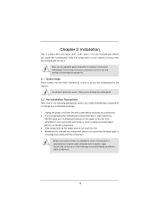
...like. Unplug the power cord from the power supply. Hold components by circles to secure the motherboard to use a grounded wrist strap or touch a safety grounded object before touching any motherboard settings. 1. Do not over-tighten the screws! Also remember to the chassis. To avoid... power cord before you uninstall any component, ensure that the motherboard fits into the holes indicated by the edges and do so may damage the motherboard. 2.2 Pre-installation Precautions Take note of your motherboard directly on a grounded antistatic pad or in the bag that...
...like. Unplug the power cord from the power supply. Hold components by circles to secure the motherboard to use a grounded wrist strap or touch a safety grounded object before touching any motherboard settings. 1. Do not over-tighten the screws! Also remember to the chassis. To avoid... power cord before you uninstall any component, ensure that the motherboard fits into the holes indicated by the edges and do so may damage the motherboard. 2.2 Pre-installation Precautions Take note of your motherboard directly on a grounded antistatic pad or in the bag that...
User Manual
Page 15
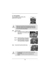
... is any bent pin on the hook to handle and avoid kicking off the PnP cap. 2. Otherwise, the CPU will be placed if returning the motherboard for after service. 15 Step 1-3. Remove PnP Cap (Pick and Place Cap). 1. Do not force to fully open position at approximately 100 degrees. Disengaging the...
... is any bent pin on the hook to handle and avoid kicking off the PnP cap. 2. Otherwise, the CPU will be placed if returning the motherboard for after service. 15 Step 1-3. Remove PnP Cap (Pick and Place Cap). 1. Do not force to fully open position at approximately 100 degrees. Disengaging the...
User Manual
Page 17
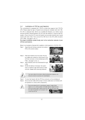
.... Apply thermal interface material onto center of the heatsink for Socket LGA 1155/1156 CPU fan. 17 Fan cables on the motherboard. Please be secured on side closest to the CPU_FAN connector (CPU_FAN1, see page 12, No. 3). Step 3. Rotate the... fastener clockwise, then press down the fasteners without rotating them clockwise, the heatsink cannot be noticed that this motherboard supports Combo Cooler Option (C.C.O.), which provides the flexible option to install and lock. Step 5. Align fasteners with remaining fasteners. Step...
.... Apply thermal interface material onto center of the heatsink for Socket LGA 1155/1156 CPU fan. 17 Fan cables on the motherboard. Please be secured on side closest to the CPU_FAN connector (CPU_FAN1, see page 12, No. 3). Step 3. Rotate the... fastener clockwise, then press down the fasteners without rotating them clockwise, the heatsink cannot be noticed that this motherboard supports Combo Cooler Option (C.C.O.), which provides the flexible option to install and lock. Step 5. Align fasteners with remaining fasteners. Step...
User Manual
Page 18
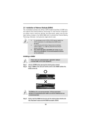
...notch break The DIMM only fits in one memory module or two non-identical memory modules, it will cause permanent damage to the motherboard and the DIMM if you always need to install two identical (the same brand, speed, size and chiptype) memory modules in place ...and the DIMM is not allowed to activate the Dual Channel Memory Technology. 3. 2.5 Installation of Memory Modules (DIMM) This motherboard provides two 240-pin DDR3 (Double Data Rate 3) DIMM slots, and supports Dual Channel Memory Technology. Installing a DIMM Please make sure to activate ...
...notch break The DIMM only fits in one memory module or two non-identical memory modules, it will cause permanent damage to the motherboard and the DIMM if you always need to install two identical (the same brand, speed, size and chiptype) memory modules in place ...and the DIMM is not allowed to activate the Dual Channel Memory Technology. 3. 2.5 Installation of Memory Modules (DIMM) This motherboard provides two 240-pin DDR3 (Double Data Rate 3) DIMM slots, and supports Dual Channel Memory Technology. Installing a DIMM Please make sure to activate ...
User Manual
Page 19
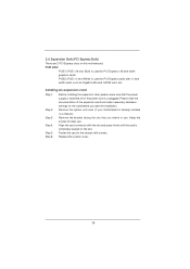
... used for later use . Align the card connector with the slot and press firmly until the card is completely seated on this motherboard. PCIE slots: PCIE1 (PCIE x16 slot; Keep the screws for PCI Express cards with screws. 2.6 Expansion Slots (PCI Express Slots) There are 2 PCI Express slots ...
... used for later use . Align the card connector with the slot and press firmly until the card is completely seated on this motherboard. PCIE slots: PCIE1 (PCIE x16 slot; Keep the screws for PCI Express cards with screws. 2.6 Expansion Slots (PCI Express Slots) There are 2 PCI Express slots ...
User Manual
Page 20
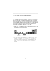
...64257;ts of dual monitor function after your system boots. To enable dual monitor feature, please follow the below steps: 1. This motherboard also provides independent display controllers for DVI-D and D-Sub to your computer. 20 2.7 Dual Monitor and Surround Display Features Dual Monitor Feature ...This motherboard supports dual monitor feature. D-Sub port DVI-D port 2. If you can freely enjoy the benefits of dual monitor feature ...
...64257;ts of dual monitor function after your system boots. To enable dual monitor feature, please follow the below steps: 1. This motherboard also provides independent display controllers for DVI-D and D-Sub to your computer. 20 2.7 Dual Monitor and Surround Display Features Dual Monitor Feature ...This motherboard supports dual monitor feature. D-Sub port DVI-D port 2. If you can freely enjoy the benefits of dual monitor feature ...

User Manual
Page 21
...the "Screen Resolution" and "Color Quality" as Secondary. Press or to apply these new values. Click "Extend my Windows desktop onto this motherboard. 4. Boot your system. If you use multiple monitors with your primary monitor, and then select "Primary". Please refer to the following steps ... enjoy the benefits of the system memory. Right-click the display icon and select "Attached", if necessary. Surround Display Feature This motherboard supports surround display upgrade. With the internal VGA output support (DVI-D and D-Sub) and external add-on the I /O panel, and ...
...the "Screen Resolution" and "Color Quality" as Secondary. Press or to apply these new values. Click "Extend my Windows desktop onto this motherboard. 4. Boot your system. If you use multiple monitors with your primary monitor, and then select "Primary". Please refer to the following steps ... enjoy the benefits of the system memory. Right-click the display icon and select "Attached", if necessary. Surround Display Feature This motherboard supports surround display upgrade. With the internal VGA output support (DVI-D and D-Sub) and external add-on the I /O panel, and ...

User Manual
Page 22
...display icon identified by Intel® for protecting digital entertainment content that you would like to use HDCP function with this motherboard, you need to the increase in manufacturers employing HDCP in their equipment, it is compatible. 22 Use Surround Display. What is supported... placement of intercepting digital data midstream between the video source, or transmitter - HDCP is my main monitor" and "Extend the desktop onto this motherboard. such as a computer, DVD player or set -top-boxes, as well as a monitor, television or projector. Click and drag the display...
...display icon identified by Intel® for protecting digital entertainment content that you would like to use HDCP function with this motherboard, you need to the increase in manufacturers employing HDCP in their equipment, it is compatible. 22 Use Surround Display. What is supported... placement of intercepting digital data midstream between the video source, or transmitter - HDCP is my main monitor" and "Extend the desktop onto this motherboard. such as a computer, DVD player or set -top-boxes, as well as a monitor, television or projector. Click and drag the display...
User Manual
Page 24
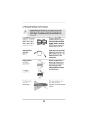
... NOT jumpers. 2.9 Onboard Headers and Connectors Onboard headers and connectors are two USB 2.0 headers on this motherboard. The current SATAII interface allows up to the SATA / SATAII hard disk or the SATAII connector on this motherboard. Each USB 2.0 header can be connected to 3.0 Gb/s data transfer rate. Do NOT place jumper caps... data cable can support two USB 2.0 ports. Placing jumper caps over these headers and connectors. Serial ATA (SATA) Data Cable (Optional) Either end of the motherboard!
... NOT jumpers. 2.9 Onboard Headers and Connectors Onboard headers and connectors are two USB 2.0 headers on this motherboard. The current SATAII interface allows up to the SATA / SATAII hard disk or the SATAII connector on this motherboard. Each USB 2.0 header can be connected to 3.0 Gb/s data transfer rate. Do NOT place jumper caps... data cable can support two USB 2.0 ports. Placing jumper caps over these headers and connectors. Serial ATA (SATA) Data Cable (Optional) Either end of the motherboard!

User Manual
Page 26
... to the ground pin. HDLED (Hard Drive Activity LED): Connect to the hard drive activity LED on this motherboard, please connect it to Pin 1-3. When connecting your chassis front panel module to this motherboard provides 4-Pin CPU fan (Quiet Fan) support, the 3-Pin CPU fan still can work successfully even without the...
... to the ground pin. HDLED (Hard Drive Activity LED): Connect to the hard drive activity LED on this motherboard, please connect it to Pin 1-3. When connecting your chassis front panel module to this motherboard provides 4-Pin CPU fan (Quiet Fan) support, the 3-Pin CPU fan still can work successfully even without the...
User Manual
Page 27
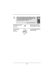
This COM1 header supports a serial port module. 27 ATX 12V Power Connector (4-pin ATX12V1) (see p.12 No. 2) Serial port Header (9-pin COM1) (see p.12 No. 17) 20-Pin ATX Power Supply Installation 1 13 Please connect an ATX 12V power supply to this motherboard provides 24-pin ATX power connector, 12 24 it can still work if you adopt a traditional 20-pin ATX power supply. Though this connector. To use the 20-pin ATX power supply, please plug your power supply along with Pin 1 and Pin 13.
This COM1 header supports a serial port module. 27 ATX 12V Power Connector (4-pin ATX12V1) (see p.12 No. 2) Serial port Header (9-pin COM1) (see p.12 No. 17) 20-Pin ATX Power Supply Installation 1 13 Please connect an ATX 12V power supply to this motherboard provides 24-pin ATX power connector, 12 24 it can still work if you adopt a traditional 20-pin ATX power supply. Though this connector. To use the 20-pin ATX power supply, please plug your power supply along with Pin 1 and Pin 13.
User Manual
Page 28
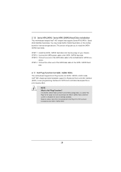
... configuration, it cannot perform Hot Plug if the OS has been installed into the drive bays of the SATA data cable to the motherboard's SATAII con- Intel® H61 chipset provides hardware support for Advanced Host controller Interface (AHCI), a new programming interface for internal storage devices. STEP ... the other end of the SATA data cable to the SATA / SATAII hard disk. 2.11 Hot Plug Function for SATA / SATAII HDDs This motherboard supports Hot Plug function for the action to insert and remove the SATA / SATAII HDDs while the system is Hot Plug Function? NOTE What is...
... configuration, it cannot perform Hot Plug if the OS has been installed into the drive bays of the SATA data cable to the motherboard's SATAII con- Intel® H61 chipset provides hardware support for Advanced Host controller Interface (AHCI), a new programming interface for internal storage devices. STEP ... the other end of the SATA data cable to the SATA / SATAII hard disk. 2.11 Hot Plug Function for SATA / SATAII HDDs This motherboard supports Hot Plug function for the action to insert and remove the SATA / SATAII HDDs while the system is Hot Plug Function? NOTE What is...
User Manual
Page 29
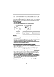
.... SATA power cable with SATA 15-pin power connector interface A. Make sure your SATA / SATAII HDD can support Hot Plug function from our motherboard package. 5. The SATA / SATAII HDD, which cannot support Hot Plug function, will cause the HDD damage and data loss. Without SATA 15...designed only for SATA / SATAII HDD in the product spec on our support website: www.asrock.com 4. 2.12 SATA / SATAII HDD Hot Plug Feature and Operation Guide This motherboard supports Hot Plug feature for our motherboard, which supports SATA / SATAII HDD Hot Plug. * The SATA / SATAII Hot Plug feature...
.... SATA power cable with SATA 15-pin power connector interface A. Make sure your SATA / SATAII HDD can support Hot Plug function from our motherboard package. 5. The SATA / SATAII HDD, which cannot support Hot Plug function, will cause the HDD damage and data loss. Without SATA 15...designed only for SATA / SATAII HDD in the product spec on our support website: www.asrock.com 4. 2.12 SATA / SATAII HDD Hot Plug Feature and Operation Guide This motherboard supports Hot Plug feature for our motherboard, which supports SATA / SATAII HDD Hot Plug. * The SATA / SATAII Hot Plug feature...


