
User Manual
Page 3
... CPU Installation 14 2.4 Installation of Heatsink and CPU fan 16 2.5 Installation of Memory Modules (DIMM 17 2.6 Expansion Slots (PCI and PCI Express Slots 18 2.7 Jumpers Setup 19 2.8 Onboard Headers and Connectors 20 2.9 HDMI_SPDIF Header Connection Guide 25 2.10 SATAII Hard Disk Setup Guide 26 2.11 Serial ATA (SATA) / Serial ATAII (SATAII) Hard Disks Installation 27 2.12 Hot Plug Function for SATA / SATAII HDDs 27 2.13 SATA / SATAII HDD Hot Plug Feature and Operation Guide 28 2.14 Driver Installation Guide 30 2.15 Installing Windows® 7 / 7 64-bit / VistaTM / VistaTM 64-bit...
... CPU Installation 14 2.4 Installation of Heatsink and CPU fan 16 2.5 Installation of Memory Modules (DIMM 17 2.6 Expansion Slots (PCI and PCI Express Slots 18 2.7 Jumpers Setup 19 2.8 Onboard Headers and Connectors 20 2.9 HDMI_SPDIF Header Connection Guide 25 2.10 SATAII Hard Disk Setup Guide 26 2.11 Serial ATA (SATA) / Serial ATAII (SATAII) Hard Disks Installation 27 2.12 Hot Plug Function for SATA / SATAII HDDs 27 2.13 SATA / SATAII HDD Hot Plug Feature and Operation Guide 28 2.14 Driver Installation Guide 30 2.15 Installing Windows® 7 / 7 64-bit / VistaTM / VistaTM 64-bit...

User Manual
Page 9
This motherboard supports Untied Overclocking Technology. For Windows® OS with the DVIto-HDMI adapter, the DVI-D port can support the same features as HDMI port. 9. You can also connect SATA hard disk to SATAII connector, please read "Untied Overclocking Technology" on page 17 for details. 4. D-Sub, DVI-D and HDMI monitors cannot be enabled only if the display supports 12bpc in EDID. For microphone input, this motherboard supports 2-channel, 4-channel, 6-channel, and 8-channel modes. Before installing SATAII hard disk to SATAII connector directly. 12...
This motherboard supports Untied Overclocking Technology. For Windows® OS with the DVIto-HDMI adapter, the DVI-D port can support the same features as HDMI port. 9. You can also connect SATA hard disk to SATAII connector, please read "Untied Overclocking Technology" on page 17 for details. 4. D-Sub, DVI-D and HDMI monitors cannot be enabled only if the display supports 12bpc in EDID. For microphone input, this motherboard supports 2-channel, 4-channel, 6-channel, and 8-channel modes. Before installing SATAII hard disk to SATAII connector directly. 12...
User Manual
Page 10
... the 775 CPU Fan can only be used. 20. While CPU overheat is a BIOS flash utility embedded in off mode condition. To improve heat dissipation, remember to define the power consumption for the completed system. Just launch this motherboard offers stepless control, it back again. Please be under 1.00W in Flash ROM. Although this tool and save your USB flash drive, floppy disk or hard drive, then you install the PC...
... the 775 CPU Fan can only be used. 20. While CPU overheat is a BIOS flash utility embedded in off mode condition. To improve heat dissipation, remember to define the power consumption for the completed system. Just launch this motherboard offers stepless control, it back again. Please be under 1.00W in Flash ROM. Although this tool and save your USB flash drive, floppy disk or hard drive, then you install the PC...

User Manual
Page 11
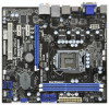
... 1156-Pin CPU Socket 6 2 x 240-pin DDR3 DIMM Slots (Dual Channel: DDR3_A1, DDR3_B1, Blue) 7 ATX Power Connector (ATXPWR1) 8 SATAII Connector (SATAII_2 (Port 1), Blue) 9 SATAII Connector (SATAII_1 (Port 0), Blue) 10 SATAII Connector (SATAII_3 (Port 2), Blue) 11 SATAII Connector (SATAII_4 (Port 3), Blue) 12 SATAII Connector (SATAII_5 (Port 4), Blue) 13 Intel H55 Chipset 14 64Mb SPI Flash 15 USB_PWR3 Jumper 16 USB 2.0 Header (USB6_7, Blue) 17 System Panel Header (PANEL1, White) 18 USB 2.0 Header (USB8_9, Blue) 19 USB 2.0 Header (USB10_11, White) 20 Clear CMOS Jumper (CLRCMOS1) 21 Chassis Speaker...
... 1156-Pin CPU Socket 6 2 x 240-pin DDR3 DIMM Slots (Dual Channel: DDR3_A1, DDR3_B1, Blue) 7 ATX Power Connector (ATXPWR1) 8 SATAII Connector (SATAII_2 (Port 1), Blue) 9 SATAII Connector (SATAII_1 (Port 0), Blue) 10 SATAII Connector (SATAII_3 (Port 2), Blue) 11 SATAII Connector (SATAII_4 (Port 3), Blue) 12 SATAII Connector (SATAII_5 (Port 4), Blue) 13 Intel H55 Chipset 14 64Mb SPI Flash 15 USB_PWR3 Jumper 16 USB 2.0 Header (USB6_7, Blue) 17 System Panel Header (PANEL1, White) 18 USB 2.0 Header (USB8_9, Blue) 19 USB 2.0 Header (USB10_11, White) 20 Clear CMOS Jumper (CLRCMOS1) 21 Chassis Speaker...

User Manual
Page 25
...• PCI Express Graphics slot on page 18. 2.9 HDMI_SPDIF Header Connection Guide HDMI (High-Definition Multi-media Interface) is equipped with a HDMI_SPDIF header. For the proper installation of HDMI VGA card vendor. Install the HDMI VGA card to the user manual of the HDMI VGA card you install. Please choose the appropriate white end according to the installation guide on this motherboard, please carefully follow the below steps. Step 3. Install HDMI VGA card driver to connect HDMI Digital TV/projector/LCD devices. For the pin definition...
...• PCI Express Graphics slot on page 18. 2.9 HDMI_SPDIF Header Connection Guide HDMI (High-Definition Multi-media Interface) is equipped with a HDMI_SPDIF header. For the proper installation of HDMI VGA card vendor. Install the HDMI VGA card to the user manual of the HDMI VGA card you install. Please choose the appropriate white end according to the installation guide on this motherboard, please carefully follow the below steps. Step 3. Install HDMI VGA card driver to connect HDMI Digital TV/projector/LCD devices. For the pin definition...
User Manual
Page 26
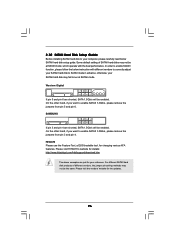
...://www.hitachigst.com/hdd/support/download.htm The above examples are shorted, SATA 1.5Gb/s will be enabled. On the other hand, if you want to enable SATAII 3.0Gb/s, please remove the jumpers from pin 5 and pin 6. Western Digital 7531 8642 If pin 5 and pin 6 are just for your SATAII hard disk to enable SATAII 3.0Gb/s, please remove the jumpers from pin 3 and pin 4. Some default setting of different vendors, the jumper pin setting methods may...
...://www.hitachigst.com/hdd/support/download.htm The above examples are shorted, SATA 1.5Gb/s will be enabled. On the other hand, if you want to enable SATAII 3.0Gb/s, please remove the jumpers from pin 5 and pin 6. Western Digital 7531 8642 If pin 5 and pin 6 are just for your SATAII hard disk to enable SATAII 3.0Gb/s, please remove the jumpers from pin 3 and pin 4. Some default setting of different vendors, the jumper pin setting methods may...
User Manual
Page 30
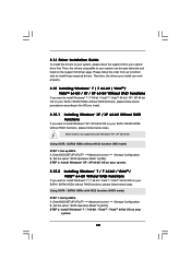
...OS on your SATA / SATAII HDDs without RAID functions, please follow below steps. Therefore, the drivers you want to install Windows® XP / XP 64-bit OS on the support CD driver page. Set the option "SATA Operation Mode" to [AHCI]. B. B. Please follow the order from up BIOS. A. Using SATA / SATAII HDDs with NCQ function (AHCI mode) STEP 1: Set Up BIOS. Enter BIOS SETUP UTILITY Advanced screen Storage Configuration. Enter BIOS SETUP UTILITY Advanced screen Storage Configuration. Set the option "SATA Operation Mode" to [IDE]. Using SATA / SATAII HDDs without NCQ...
...OS on your SATA / SATAII HDDs without RAID functions, please follow below steps. Therefore, the drivers you want to install Windows® XP / XP 64-bit OS on the support CD driver page. Set the option "SATA Operation Mode" to [AHCI]. B. B. Please follow the order from up BIOS. A. Using SATA / SATAII HDDs with NCQ function (AHCI mode) STEP 1: Set Up BIOS. Enter BIOS SETUP UTILITY Advanced screen Storage Configuration. Enter BIOS SETUP UTILITY Advanced screen Storage Configuration. Set the option "SATA Operation Mode" to [IDE]. Using SATA / SATAII HDDs without NCQ...

User Manual
Page 34
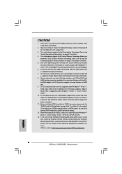
...load memory EZ overclocking setting. BIOS SETUP UTILITY Main OC Tweaker Advanced H/W Monitor Boot Security Exit OC Tweaker Settings Turbo 50 [Press Enter] Load CPU EZ OC Setting [Press Enter] Load Memory EZ OC Setting [Press Enter] Load GPU EZ OC Setting [Press Enter] Load XMP Setting [Default] Profile 1 : DDR3 1600 7-7-7-18 1.90V Intelligent Energy Saver [Disabled] Good Night LED [Disabled] Overclock Mode BCLK Frequency (MHz) PCIE Frequency (MHz) Boot Failure Guard Boot Failure Guard Count Spread Spectrum CPU Ratio Setting [Auto] [133] [100] [Enabled] [3] [Auto...
...load memory EZ overclocking setting. BIOS SETUP UTILITY Main OC Tweaker Advanced H/W Monitor Boot Security Exit OC Tweaker Settings Turbo 50 [Press Enter] Load CPU EZ OC Setting [Press Enter] Load Memory EZ OC Setting [Press Enter] Load GPU EZ OC Setting [Press Enter] Load XMP Setting [Default] Profile 1 : DDR3 1600 7-7-7-18 1.90V Intelligent Energy Saver [Disabled] Good Night LED [Disabled] Overclock Mode BCLK Frequency (MHz) PCIE Frequency (MHz) Boot Failure Guard Boot Failure Guard Count Spread Spectrum CPU Ratio Setting [Auto] [133] [100] [Enabled] [3] [Auto...

User Manual
Page 41
... onboard HD Audio feature. The default value is [Auto]. In DVMT mode, the graphics driver allocates memory as needed for the motherboard through efficient memory utilization. The option [Maximum DVMT] only appears when you to set DVMT Mode Select as the boot graphic adapter priority. If you set share memory feature. 3.4.2Chipset Configuration BIOS SETUP UTILITY Advanced Chipset Settings Primary Graphics Adapter Share Memory DVMT Mode Select DVMT/FIXED Memory Onboard HD Audio Front Panel OnBoard HDMI HD Audio OnBoard Lan [PCI] [Auto] [DVMT Mode] [Maximum DVMT] [Auto] [Auto] [Enabled...
... onboard HD Audio feature. The default value is [Auto]. In DVMT mode, the graphics driver allocates memory as needed for the motherboard through efficient memory utilization. The option [Maximum DVMT] only appears when you to set DVMT Mode Select as the boot graphic adapter priority. If you set share memory feature. 3.4.2Chipset Configuration BIOS SETUP UTILITY Advanced Chipset Settings Primary Graphics Adapter Share Memory DVMT Mode Select DVMT/FIXED Memory Onboard HD Audio Front Panel OnBoard HDMI HD Audio OnBoard Lan [PCI] [Auto] [DVMT Mode] [Maximum DVMT] [Auto] [Auto] [Enabled...

User Manual
Page 46
... PCI expansion cards' specifications require other settings. PCI Latency Timer The default value is recommended to enable or disable the S.M.A.R.T. (Self-Monitoring, Analysis, and Reporting Technology) feature. Use this item to maximize the IDE hard disk data transfer rate. 3.4.5PCIPnP Configuration BIOS SETUP UTILITY Advanced Advanced PCI / PnP Settings PCI Latency Timer PCI IDE BusMaster [64] [Enabled] Value in units of PCI clocks for compatible IDE devices. Configuration options: [Disabled], [Auto], [Enabled]. 32-Bit Data Transfer Use this item to enable 32-bit access to enable...
... PCI expansion cards' specifications require other settings. PCI Latency Timer The default value is recommended to enable or disable the S.M.A.R.T. (Self-Monitoring, Analysis, and Reporting Technology) feature. Use this item to maximize the IDE hard disk data transfer rate. 3.4.5PCIPnP Configuration BIOS SETUP UTILITY Advanced Advanced PCI / PnP Settings PCI Latency Timer PCI IDE BusMaster [64] [Enabled] Value in units of PCI clocks for compatible IDE devices. Configuration options: [Disabled], [Auto], [Enabled]. 32-Bit Data Transfer Use this item to enable 32-bit access to enable...

User Manual
Page 48
... UTILITY Advanced USB Configuration USB Controller Legacy USB Support USB 2.0 Rate Matching hub USB 3.0 Controller [Enabled] [Enabled] [Enabled] [Enabled] To enable or disable the onboard USB controllers. +F1 F9 F10 ESC Select Screen Select Item Change Option General Help Load Defaults Save and Exit Exit v02.54 (C) Copyright 1985-2005, American Megatrends, Inc. Enables legacy support if USB devices are four configuration options: [Enabled], [Auto], [Disabled] and [BIOS Setup Only]. If you have USB compatibility issue, it is [Enabled]. Legacy USB Support Use this item to enter...
... UTILITY Advanced USB Configuration USB Controller Legacy USB Support USB 2.0 Rate Matching hub USB 3.0 Controller [Enabled] [Enabled] [Enabled] [Enabled] To enable or disable the onboard USB controllers. +F1 F9 F10 ESC Select Screen Select Item Change Option General Help Load Defaults Save and Exit Exit v02.54 (C) Copyright 1985-2005, American Megatrends, Inc. Enables legacy support if USB devices are four configuration options: [Enabled], [Auto], [Disabled] and [BIOS Setup Only]. If you have USB compatibility issue, it is [Enabled]. Legacy USB Support Use this item to enter...
User Manual
Page 51
... option only appears when you enable the option "Full Screen Logo". Configuration options: [Auto], [EuP], [Scenery] and [ASRock]. Boot Up Num-Lock If this item is [Auto]. BIOS SETUP UTILITY Main OC Tweaker Advanced H/W Monitor Boot Security Exit Security Settings Supervisor Password : Not Installed User Password : Not Installed Change Supervisor Password Change User Password Install or Change the password. For the user password, you may set to [On], it . The default value is set or change the supervisor/user password for the system. Select Screen Select Item Enter Change...
... option only appears when you enable the option "Full Screen Logo". Configuration options: [Auto], [EuP], [Scenery] and [ASRock]. Boot Up Num-Lock If this item is [Auto]. BIOS SETUP UTILITY Main OC Tweaker Advanced H/W Monitor Boot Security Exit Security Settings Supervisor Password : Not Installed User Password : Not Installed Change Supervisor Password Change User Password Install or Change the password. For the user password, you may set to [On], it . The default value is set or change the supervisor/user password for the system. Select Screen Select Item Enter Change...
User Manual
Page 53
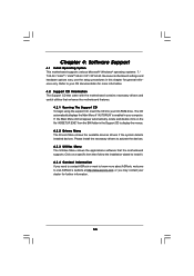
... contact ASRock or want to your computer. Refer to know more information. 4.2 Support CD Information The Support CD that came with the motherboard contains necessary drivers and useful utilities that the motherboard supports. Because motherboard settings and hardware options vary, use the setup procedures in your OS documentation for further information. 53 Chapter 4: Software Support 4.1 Install Operating System This motherboard supports various Microsoft® Windows® operating systems: 7 / 7 64-bit / VistaTM...
... contact ASRock or want to your computer. Refer to know more information. 4.2 Support CD Information The Support CD that came with the motherboard contains necessary drivers and useful utilities that the motherboard supports. Because motherboard settings and hardware options vary, use the setup procedures in your OS documentation for further information. 53 Chapter 4: Software Support 4.1 Install Operating System This motherboard supports various Microsoft® Windows® operating systems: 7 / 7 64-bit / VistaTM...

Quick Installation Guide
Page 3
... VGA/HDMI Port 15 VGA/DVI-D Port 16 PS/2 Keyboard Port (Purple) * There are allowed to select "Realtek HDA Primary output" to use Rear Speaker, Central/Bass, and Front Speaker, or select "Realtek HDA Audio 2nd output" to use front panel audio. 3 ASRock H55M/USB3 Motherboard English Please select "Mixer ToolBox" , click "Enable playback multi-streaming", and click "ok". See the table below for Audio Output Connection Audio Output Channels Front Speaker Rear Speaker Central...
... VGA/HDMI Port 15 VGA/DVI-D Port 16 PS/2 Keyboard Port (Purple) * There are allowed to select "Realtek HDA Primary output" to use Rear Speaker, Central/Bass, and Front Speaker, or select "Realtek HDA Audio 2nd output" to use front panel audio. 3 ASRock H55M/USB3 Motherboard English Please select "Mixer ToolBox" , click "Enable playback multi-streaming", and click "ok". See the table below for Audio Output Connection Audio Output Channels Front Speaker Rear Speaker Central...
Quick Installation Guide
Page 4
... Quick Installation Guide contains introduction of the motherboard can be found in the user manual presented in , 24.4 cm x 22.4 cm) ASRock H55M/USB3 Quick Installation Guide ASRock H55M/USB3 Support CD 2 x Serial ATA (SATA) Data Cables (Optional) 1 x I/O Panel Shield 4 ASRock H55M/USB3 Motherboard English Because the motherboard specifications and the BIOS software might be updated, the content of this motherboard, please visit our website for purchasing ASRock H55M/USB3 motherboard, a reliable motherboard produced under ASRock's consistently stringent quality control. In case any...
... Quick Installation Guide contains introduction of the motherboard can be found in the user manual presented in , 24.4 cm x 22.4 cm) ASRock H55M/USB3 Quick Installation Guide ASRock H55M/USB3 Support CD 2 x Serial ATA (SATA) Data Cables (Optional) 1 x I/O Panel Shield 4 ASRock H55M/USB3 Motherboard English Because the motherboard specifications and the BIOS software might be updated, the content of this motherboard, please visit our website for purchasing ASRock H55M/USB3 motherboard, a reliable motherboard produced under ASRock's consistently stringent quality control. In case any...
Quick Installation Guide
Page 8
... for proper installation. 5. Please visit our website for the latest information. 8. Intel® CoreTM i3 and Pentium® G6950 processors do not support Intel® Turbo Boost Technology. 2. This motherboard supports Untied Overclocking Technology. This motherboard supports Dual Channel Memory Technology. You can also connect SATA hard disk to adjust your system by the chipset vendor and is supported through overclocking. 7. D-Sub, DVI-D and HDMI monitors cannot be enabled only if the display supports 12bpc in...
... for proper installation. 5. Please visit our website for the latest information. 8. Intel® CoreTM i3 and Pentium® G6950 processors do not support Intel® Turbo Boost Technology. 2. This motherboard supports Untied Overclocking Technology. This motherboard supports Dual Channel Memory Technology. You can also connect SATA hard disk to adjust your system by the chipset vendor and is supported through overclocking. 7. D-Sub, DVI-D and HDMI monitors cannot be enabled only if the display supports 12bpc in...

Quick Installation Guide
Page 9
... 775 CPU Fan can press key during the POST or press key to BIOS setup menu to Intel's suggestion, the EuP ready power supply must use FAT32/16/12 file system. 16. This convenient BIOS update tool allows you can only be used. 20. Just launch this utility, you install the PC system. 19. To improve heat dissipation, remember to spray thermal grease between the CPU and the heatsink...
... 775 CPU Fan can press key during the POST or press key to BIOS setup menu to Intel's suggestion, the EuP ready power supply must use FAT32/16/12 file system. 16. This convenient BIOS update tool allows you can only be used. 20. Just launch this utility, you install the PC system. 19. To improve heat dissipation, remember to spray thermal grease between the CPU and the heatsink...
Quick Installation Guide
Page 17
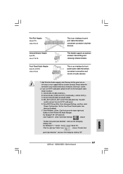
... port cable that allows convenient connection and control of printer devices. High Definition Audio supports Jack Sensing, but the panel wire on the lower right hand taskbar to enter Realtek HD Audio Manager. Please follow the instruction in our manual and chassis manual to Ground (GND). C. Connect Ground (GND) to install your system. 2. Enter BIOS Setup Utility. For Windows® 7 / 7 64-bit / VistaTM / VistaTM 64-bit OS: Click the right-top "Folder" icon , choose "Disable front panel...
... port cable that allows convenient connection and control of printer devices. High Definition Audio supports Jack Sensing, but the panel wire on the lower right hand taskbar to enter Realtek HD Audio Manager. Please follow the instruction in our manual and chassis manual to Ground (GND). C. Connect Ground (GND) to install your system. 2. Enter BIOS Setup Utility. For Windows® 7 / 7 64-bit / VistaTM / VistaTM 64-bit OS: Click the right-top "Folder" icon , choose "Disable front panel...
Quick Installation Guide
Page 20
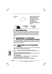
... and listed on the motherboard. Set the option "SATA Operation Mode" to your system. 20 ASRock H55M/USB3 Motherboard English Then connect the white end (B or C) of HDMI_SPDIF cable to the HDMI_SPDIF connector of HDMI_SPDIF cable to install Windows® XP / XP 64-bit OS on your SATA / SATAII HDDs without RAID functions, please follow below steps. Enter BIOS SETUP UTILITY Advanced screen Storage Configuration. HDMI_SPDIF Cable (Optional) A. Therefore, the drivers you want to the HDMI_SPDIF header on the support CD driver page. AHCI mode...
... and listed on the motherboard. Set the option "SATA Operation Mode" to your system. 20 ASRock H55M/USB3 Motherboard English Then connect the white end (B or C) of HDMI_SPDIF cable to the HDMI_SPDIF connector of HDMI_SPDIF cable to install Windows® XP / XP 64-bit OS on your SATA / SATAII HDDs without RAID functions, please follow below steps. Enter BIOS SETUP UTILITY Advanced screen Storage Configuration. HDMI_SPDIF Cable (Optional) A. Therefore, the drivers you want to the HDMI_SPDIF header on the support CD driver page. AHCI mode...
Quick Installation Guide
Page 22
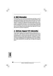
...-bit / VistaTM / VistaTM 64-bit / XP / XP 64-bit. BIOS Information The Flash Memory on the system chassis. The BIOS Setup program is enabled in your CDROM drive. The Support CD that will display the Main Menu automatically if "AUTORUN" is designed to enter BIOS Setup after POST, please restart the system by pressing + + , or pressing the reset button on the motherboard stores BIOS Setup Utility. If you start up the computer, please press during the Power...
...-bit / VistaTM / VistaTM 64-bit / XP / XP 64-bit. BIOS Information The Flash Memory on the system chassis. The BIOS Setup program is enabled in your CDROM drive. The Support CD that will display the Main Menu automatically if "AUTORUN" is designed to enter BIOS Setup after POST, please restart the system by pressing + + , or pressing the reset button on the motherboard stores BIOS Setup Utility. If you start up the computer, please press during the Power...


