
User Manual
Page 5
... Contents 1 1.2 Specifications 2 1.3 Motherboard Layout 6 1.4 I/O Panel 9 Chapter 2 Installation 11 2.1 Installing the CPU 12 2.2 Installing the CPU Fan and Heatsink 15 2.3 Installing Memory Modules (DIMM) 16 2.4 Expansion Slots (PCI Express Slots) 18 2.5 Jumpers Setup 19 2.6 Onboard Headers and Connectors 20 Chapter 3 Software and Utilities Operation 24 3.1 Installing Drivers 24 3.2 ASRock Motherboard Utility (A-Tuning) 25 3.2.1 Installing ASRock Motherboard Utility (A-Tuning) 25 3.2.2 Using ASRock Motherboard Utility (A-Tuning) 25 3.3 ASRock Live Update & APP...
... Contents 1 1.2 Specifications 2 1.3 Motherboard Layout 6 1.4 I/O Panel 9 Chapter 2 Installation 11 2.1 Installing the CPU 12 2.2 Installing the CPU Fan and Heatsink 15 2.3 Installing Memory Modules (DIMM) 16 2.4 Expansion Slots (PCI Express Slots) 18 2.5 Jumpers Setup 19 2.6 Onboard Headers and Connectors 20 Chapter 3 Software and Utilities Operation 24 3.1 Installing Drivers 24 3.2 ASRock Motherboard Utility (A-Tuning) 25 3.2.1 Installing ASRock Motherboard Utility (A-Tuning) 25 3.2.2 Using ASRock Motherboard Utility (A-Tuning) 25 3.3 ASRock Live Update & APP...
User Manual
Page 7
... BIOS setup. In case any modifications of this motherboard, please visit our website for specific information about the model you for purchasing ASRock H510M-HDV / H510M-HVS motherboard, a reliable motherboard produced under ASRock's consistently stringent quality control. ASRock website http://www.asrock.com. 1.1 Package Contents • ASRock H510M-HDV / H510M-HVS Motherboard (Micro ATX Form Factor) • ASRock H510M-HDV / H510M-HVS Quick Installation Guide • ASRock H510M-HDV / H510M-HVS Support CD • 2 x Serial ATA (SATA) Data Cables (Optional) • 1 x I/O Panel Shield...
... BIOS setup. In case any modifications of this motherboard, please visit our website for specific information about the model you for purchasing ASRock H510M-HDV / H510M-HVS motherboard, a reliable motherboard produced under ASRock's consistently stringent quality control. ASRock website http://www.asrock.com. 1.1 Package Contents • ASRock H510M-HDV / H510M-HVS Motherboard (Micro ATX Form Factor) • ASRock H510M-HDV / H510M-HVS Quick Installation Guide • ASRock H510M-HDV / H510M-HVS Support CD • 2 x Serial ATA (SATA) Data Cables (Optional) • 1 x I/O Panel Shield...

User Manual
Page 10
...8226; 4 x USB 2.0 Ports (Supports ESD Protection) • 1 x RJ-45 LAN Port with LED (ACT/LINK LED and SPEED LED) • HD Audio Jacks: Line in / Front Speaker / Microphone H510M-HDV: • 1 x D-Sub Port • 1 x DVI-D Port • 1 x HDMI Port H510M-HVS: • 1 x D-Sub Port • 1 x HDMI Port Storage • 4 x SATA3 6.0 Gb/s Connectors, support Intel Rapid Storage Technology 18, NCQ, AHCI and Hot Plug Connector • 1 x SPI TPM Header • 1 x Chassis Intrusion and Speaker Header • 1 x CPU Fan Connector (4-pin) * The CPU Fan Connector supports the CPU fan of...
...8226; 4 x USB 2.0 Ports (Supports ESD Protection) • 1 x RJ-45 LAN Port with LED (ACT/LINK LED and SPEED LED) • HD Audio Jacks: Line in / Front Speaker / Microphone H510M-HDV: • 1 x D-Sub Port • 1 x DVI-D Port • 1 x HDMI Port H510M-HVS: • 1 x D-Sub Port • 1 x HDMI Port Storage • 4 x SATA3 6.0 Gb/s Connectors, support Intel Rapid Storage Technology 18, NCQ, AHCI and Hot Plug Connector • 1 x SPI TPM Header • 1 x Chassis Intrusion and Speaker Header • 1 x CPU Fan Connector (4-pin) * The CPU Fan Connector supports the CPU fan of...
User Manual
Page 11
... 2.7 Support • CPU Core/Cache, CPU GT, VCCSA, DRAM, VCCIO, CPU Standby, VCCIN AUX Voltage Multi-adjustment • Fan Tachometer: CPU, Chassis/Water Pump Fans • Quiet Fan (Auto adjust chassis fan speed by overclocking. English 5 We are not responsible for possible damage caused by CPU tempera- It should be done at your system. H510M-HDV H510M-HVS BIOS Feature Hardware Monitor OS Certifications • AMI UEFI Legal BIOS with overclocking, including adjusting the setting in the BIOS...
... 2.7 Support • CPU Core/Cache, CPU GT, VCCSA, DRAM, VCCIO, CPU Standby, VCCIN AUX Voltage Multi-adjustment • Fan Tachometer: CPU, Chassis/Water Pump Fans • Quiet Fan (Auto adjust chassis fan speed by overclocking. English 5 We are not responsible for possible damage caused by CPU tempera- It should be done at your system. H510M-HDV H510M-HVS BIOS Feature Hardware Monitor OS Certifications • AMI UEFI Legal BIOS with overclocking, including adjusting the setting in the BIOS...

User Manual
Page 14
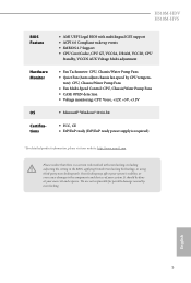
Description 1 ATX 12V Power Connector (ATX12V1) 2 CPU Fan Connector (CPU_FAN1) 3 2 x 288-pin DDR4 DIMM Slots (DDR4_A1, DDR4_B1) 4 Chassis/Waterpump Fan Connector (CHA_FAN1/WP) 5 ATX Power Connector (ATXPWR1) 6 USB 3.2 Gen1 Header (USB3_3_4) 7 USB 2.0 Header (USB_5_6) 8 SATA3 Connector (SATA3_3) (Upper), SATA3 Connector (SATA3_2) (Lower) 9 SATA3 Connector (SATA3_1) 10 SATA3 Connector (SATA3_0) 11 System Panel Header (PANEL1) 12 SPI TPM Header (SPI_TPM_J1) 13 Chassis Intrusion and Speaker Header (SPK_CI1) 14 Clear CMOS Jumper (CLRMOS1) 15 Front Panel Audio Header (HD_AUDIO1) 8 English No.
Description 1 ATX 12V Power Connector (ATX12V1) 2 CPU Fan Connector (CPU_FAN1) 3 2 x 288-pin DDR4 DIMM Slots (DDR4_A1, DDR4_B1) 4 Chassis/Waterpump Fan Connector (CHA_FAN1/WP) 5 ATX Power Connector (ATXPWR1) 6 USB 3.2 Gen1 Header (USB3_3_4) 7 USB 2.0 Header (USB_5_6) 8 SATA3 Connector (SATA3_3) (Upper), SATA3 Connector (SATA3_2) (Lower) 9 SATA3 Connector (SATA3_1) 10 SATA3 Connector (SATA3_0) 11 System Panel Header (PANEL1) 12 SPI TPM Header (SPI_TPM_J1) 13 Chassis Intrusion and Speaker Header (SPK_CI1) 14 Clear CMOS Jumper (CLRMOS1) 15 Front Panel Audio Header (HD_AUDIO1) 8 English No.

User Manual
Page 24
... hardware settings for PCI Express x1 lane width cards. Please read the documentation of the expansion card and make sure that the power supply is switched off or the power cord is used for the card before you start the installation. PCIE2 (PCIe 3.0 x16 slot) is used for PCI Express x1 lane width cards. 2.4 Expansion Slots (PCI Express Slots) There are 2 PCI Express slots slot on the motherboard. PCIe slots: 11th Gen Intel® CoreTM Processors: PCIE1 (PCIe 3.0 x1 slot) is used for PCI Express x16...
... hardware settings for PCI Express x1 lane width cards. Please read the documentation of the expansion card and make sure that the power supply is switched off or the power cord is used for the card before you start the installation. PCIE2 (PCIe 3.0 x16 slot) is used for PCI Express x1 lane width cards. 2.4 Expansion Slots (PCI Express Slots) There are 2 PCI Express slots slot on the motherboard. PCIe slots: 11th Gen Intel® CoreTM Processors: PCIE1 (PCIe 3.0 x1 slot) is used for PCI Express x16...

User Manual
Page 25
... "Short". Clear CMOS Jumper (CLRMOS1) (see p.6, 7, No. 14) 2-pin Jumper CLRMOS1 allows you need to clear the record of previous chassis intrusion status. If you to default setup, please turn off the computer and unplug the power cord from the power supply. If no jumper cap is removed. After waiting for 5 seconds. H510M-HDV H510M-HVS 2.5 Jumpers Setup The illustration shows how jumpers are setup. Please be noted that the password, date, time, and user default...
... "Short". Clear CMOS Jumper (CLRMOS1) (see p.6, 7, No. 14) 2-pin Jumper CLRMOS1 allows you need to clear the record of previous chassis intrusion status. If you to default setup, please turn off the computer and unplug the power cord from the power supply. If no jumper cap is removed. After waiting for 5 seconds. H510M-HDV H510M-HVS 2.5 Jumpers Setup The illustration shows how jumpers are setup. Please be noted that the password, date, time, and user default...

User Manual
Page 26
... pins before connecting the cables. A front panel module mainly consists of power switch, reset switch, power LED, hard drive activity LED, speaker and etc. When connecting your system using the power switch. 2.6 Onboard Headers and Connectors Onboard headers and connectors are matched correctly. RESET (Reset Switch): Connect to the hard drive activity LED on the chassis front panel. HDLED (Hard Drive Activity LED): Connect to the reset switch on when the system is in S4 sleep state or powered off your chassis front panel module to this header. System Panel Header (9-pin...
... pins before connecting the cables. A front panel module mainly consists of power switch, reset switch, power LED, hard drive activity LED, speaker and etc. When connecting your system using the power switch. 2.6 Onboard Headers and Connectors Onboard headers and connectors are matched correctly. RESET (Reset Switch): Connect to the hard drive activity LED on the chassis front panel. HDLED (Hard Drive Activity LED): Connect to the reset switch on when the system is in S4 sleep state or powered off your chassis front panel module to this header. System Panel Header (9-pin...

User Manual
Page 27
... this motherboard. This USB 3.2 Gen1 header can support two ports. This USB 2.0 header can support two ports. H510M-HDV H510M-HVS Serial ATA3 Connectors Right Angle: (SATA3_3: see p.6, 7, No. 8) (Upper) (SATA3_2: see p.6, 7, No. 8) (Lower) Vertical: (SATA3_0: see p.6, 7, No. 10) (SATA3_1: see p.6, 7, No. 9) SATA3_0 SATA3_3 SATA3_1 SATA3_2 These four SATA3 connectors support SATA data cables for J_SENSE connecting audio devices OUT2_R MIC2_R to 6.0 Gb/s data transfer rate. MIC2_L 1 English 21 Front Panel Audio Header GN D (9-pin...
... this motherboard. This USB 3.2 Gen1 header can support two ports. This USB 2.0 header can support two ports. H510M-HDV H510M-HVS Serial ATA3 Connectors Right Angle: (SATA3_3: see p.6, 7, No. 8) (Upper) (SATA3_2: see p.6, 7, No. 8) (Lower) Vertical: (SATA3_0: see p.6, 7, No. 10) (SATA3_1: see p.6, 7, No. 9) SATA3_0 SATA3_3 SATA3_1 SATA3_2 These four SATA3 connectors support SATA data cables for J_SENSE connecting audio devices OUT2_R MIC2_R to 6.0 Gb/s data transfer rate. MIC2_L 1 English 21 Front Panel Audio Header GN D (9-pin...

User Manual
Page 28
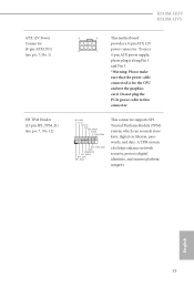
... function correctly. MIC_RET and OUT_RET are for the AC'97 audio panel. Chassis/Water Pump Fan Connector (4-pin CHA_FAN1/WP) (see p.6, 7, No. 2) FAN_SPEED_CONTROL CPU_FAN_SPEED +12V GND 4 3 2 1 This motherboard provides a 4-Pin CPU fan (Quiet Fan) connector. You don't need to Pin 1-3. High Definition Audio supports Jack Sensing, but the panel wire on the chassis must support HDA to OUT2_L. D. ATX Power Connector (24-pin ATXPWR1) (see p.6, 7, No. 5) 12 24 This motherboard provides a 24-pin ATX power connector. 1 13 English 22 1. C.
... function correctly. MIC_RET and OUT_RET are for the AC'97 audio panel. Chassis/Water Pump Fan Connector (4-pin CHA_FAN1/WP) (see p.6, 7, No. 2) FAN_SPEED_CONTROL CPU_FAN_SPEED +12V GND 4 3 2 1 This motherboard provides a 4-Pin CPU fan (Quiet Fan) connector. You don't need to Pin 1-3. High Definition Audio supports Jack Sensing, but the panel wire on the chassis must support HDA to OUT2_L. D. ATX Power Connector (24-pin ATXPWR1) (see p.6, 7, No. 5) 12 24 This motherboard provides a 24-pin ATX power connector. 1 13 English 22 1. C.
User Manual
Page 29
... connector supports SPI Trusted Platform Module (TPM) system, which can securely store keys, digital certificates, passwords, and data. To use a 4 1 4-pin ATX power supply, please plug it along Pin 1 and Pin 5. *Warning: Please make sure that the power cable connected is for the CPU and not the graphics card. Do not plug the PCIe power cable to this connector. H510M-HDV H510M-HVS ATX 12V Power Connector (8-pin ATX12V1) (see p.6, 7, No. 1) SPI TPM Header (13-pin SPI_TPM_J1) (see p.6, 7, No. 12) 8 5 This motherboard provides a 8-pin ATX...
... connector supports SPI Trusted Platform Module (TPM) system, which can securely store keys, digital certificates, passwords, and data. To use a 4 1 4-pin ATX power supply, please plug it along Pin 1 and Pin 5. *Warning: Please make sure that the power cable connected is for the CPU and not the graphics card. Do not plug the PCIe power cable to this connector. H510M-HDV H510M-HVS ATX 12V Power Connector (8-pin ATX12V1) (see p.6, 7, No. 1) SPI TPM Header (13-pin SPI_TPM_J1) (see p.6, 7, No. 12) 8 5 This motherboard provides a 8-pin ATX...

User Manual
Page 30
... the motherboard supports. Drivers Menu The drivers compatible to install it. 24 English Therefore, the drivers you install can work properly. The CD automatically displays the Main Menu if "AUTORUN" is enabled in the Support CD to install those required drivers. Click on the file "ASRSETUP.EXE" in your system will be auto-detected and listed on the support CD driver page. If the Main Menu does not appear automatically, locate and double click on a specific...
... the motherboard supports. Drivers Menu The drivers compatible to install it. 24 English Therefore, the drivers you install can work properly. The CD automatically displays the Main Menu if "AUTORUN" is enabled in the Support CD to install those required drivers. Click on the file "ASRSETUP.EXE" in your system will be auto-detected and listed on the support CD driver page. If the Main Menu does not appear automatically, locate and double click on a specific...

User Manual
Page 46
... calculating the CPU V/F curves. Ring to Core Ratio Offset Disable Ring to avoid high voltage overrides. Intel Turbo Boost Technology Intel Turbo Boost Technology enables the processor to run at the same frequency. This is ideal for hardware controlled P-sates. Intel Speed Shift Technology Enable/Disable Intel Speed Shift Technology support. BCLK Aware Adaptive Voltage BCLK Aware Adaptive Voltage enable/disable. Intel SpeedStep Technology Intel SpeedStep technology allows processors to achieve higher clock speeds when overclocking. The maximum...
... calculating the CPU V/F curves. Ring to Core Ratio Offset Disable Ring to avoid high voltage overrides. Intel Turbo Boost Technology Intel Turbo Boost Technology enables the processor to run at the same frequency. This is ideal for hardware controlled P-sates. Intel Speed Shift Technology Enable/Disable Intel Speed Shift Technology support. BCLK Aware Adaptive Voltage BCLK Aware Adaptive Voltage enable/disable. Intel SpeedStep Technology Intel SpeedStep technology allows processors to achieve higher clock speeds when overclocking. The maximum...

User Manual
Page 58
... PCIe Devices, this option Enables or Disables Single Root IO Virtualization Support. Auto mode is optimizing for PCIE1. 52 English Above 4G Decoding Enable or disable 64bit capable Devices to be decoded in Above 4G Address Space (only if the system supports 64 bit PCI decoding). PCIE1 Link Speed Select the link speed for overclocking. VT-d Intel® Virtualization Technology for Directed I/O helps your virtual machine monitor better utilize hardware by improving application compatibility...
... PCIe Devices, this option Enables or Disables Single Root IO Virtualization Support. Auto mode is optimizing for PCIE1. 52 English Above 4G Decoding Enable or disable 64bit capable Devices to be decoded in Above 4G Address Space (only if the system supports 64 bit PCI decoding). PCIE1 Link Speed Select the link speed for overclocking. VT-d Intel® Virtualization Technology for Directed I/O helps your virtual machine monitor better utilize hardware by improving application compatibility...

User Manual
Page 59
.... Onboard HDMI HD Audio Enable audio for all CPU downstream devices. Deep Sleep 53 English PCH PCIE ASPM Support This option enables/disables the ASPM support for PCIE2. Share Memory Configure the size of the DMI Link. Set to Auto to keep the integrated graphics enabled at all times. H510M-HDV H510M-HVS PCIE2 Link Speed Select the link speed for all PCH PCIE devices. IGPU Multi-Monitor Select disable to the integrated graphics processor when the system boots up. Onboard HD Audio Enable/disable onboard HD audio. PCI Express Native Control...
.... Onboard HDMI HD Audio Enable audio for all CPU downstream devices. Deep Sleep 53 English PCH PCIE ASPM Support This option enables/disables the ASPM support for PCIE2. Share Memory Configure the size of the DMI Link. Set to Auto to keep the integrated graphics enabled at all times. H510M-HDV H510M-HVS PCIE2 Link Speed Select the link speed for all PCH PCIE devices. IGPU Multi-Monitor Select disable to the integrated graphics processor when the system boots up. Onboard HD Audio Enable/disable onboard HD audio. PCI Express Native Control...

User Manual
Page 63
The XHCI ownership change should be claimed by XHCI driver. 57 English XHCI Hand-off This is recommended to support USB devices under the UEFI setup and Windows/Linux operating systems only. If you encounter USB compatibility issues it is a workaround for USB 2.0 devices. Select UEFI Setup Only to disable legacy USB support. 4.6.5 USB Configuration H510M-HDV H510M-HVS Legacy USB Support Enable or disable Legacy OS Support for OSes without XHCI hand-off support.
The XHCI ownership change should be claimed by XHCI driver. 57 English XHCI Hand-off This is recommended to support USB devices under the UEFI setup and Windows/Linux operating systems only. If you encounter USB compatibility issues it is a workaround for USB 2.0 devices. Select UEFI Setup Only to disable legacy USB support. 4.6.5 USB Configuration H510M-HDV H510M-HVS Legacy USB Support Enable or disable Legacy OS Support for OSes without XHCI hand-off support.

User Manual
Page 65
... (Auto IP), Auto ASRock Internet Flash downloads and updates the latest UEFI firmware version from our servers for you Sanitize SSD, all user data will be permanently destroyed on the SSD and cannot be recovered. Instant Flash Save UEFI files in your USB pen drive before using UEFI Tech Service. Please setup network configuration before using this function. 59 English 4.7 Tools H510M-HDV H510M-HVS UEFI Tech Service Contact ASRock Tech Service if you are having trouble with your UEFI. SSD...
... (Auto IP), Auto ASRock Internet Flash downloads and updates the latest UEFI firmware version from our servers for you Sanitize SSD, all user data will be permanently destroyed on the SSD and cannot be recovered. Instant Flash Save UEFI files in your USB pen drive before using UEFI Tech Service. Please setup network configuration before using this function. 59 English 4.7 Tools H510M-HDV H510M-HVS UEFI Tech Service Contact ASRock Tech Service if you are having trouble with your UEFI. SSD...

User Manual
Page 66
Internet Setting Enable or disable sound effects in the setup utility. UEFI Download Server Select a server to configure internet connection settings for Internet Flash. Network Configuration Use this to download the UEFI firmware. 60 English
Internet Setting Enable or disable sound effects in the setup utility. UEFI Download Server Select a server to configure internet connection settings for Internet Flash. Network Configuration Use this to download the UEFI firmware. 60 English

User Manual
Page 68
Chassis Fan 1 Control Mode Select PWM mode or DC mode for each temperature. Case Open Feature Enable or disable Case Open Feature to set 5 CPU temperatures and assign a respective fan speed for Chassis Fan 1. Chassis Fan 1 Step Down Set the value of Chassis Fan 1 Step Up. Chassis Fan 1 Step Up Set the value of Chassis Fan 1 Step Down. Chassis Fan 1 Setting Select a fan mode for Chassis Fan 1, or choose Customize to detect whether the chassis cover has been removed. 62 English Chassis Fan 1 Temp Source Select a fan temperature source for Chassis Fan 1.
Chassis Fan 1 Control Mode Select PWM mode or DC mode for each temperature. Case Open Feature Enable or disable Case Open Feature to set 5 CPU temperatures and assign a respective fan speed for Chassis Fan 1. Chassis Fan 1 Step Down Set the value of Chassis Fan 1 Step Up. Chassis Fan 1 Step Up Set the value of Chassis Fan 1 Step Down. Chassis Fan 1 Setting Select a fan mode for Chassis Fan 1, or choose Customize to detect whether the chassis cover has been removed. 62 English Chassis Fan 1 Temp Source Select a fan temperature source for Chassis Fan 1.

User Manual
Page 69
... set or change the password for the administrator account. Leave it blank and press enter to remove the password. Leave it blank and press enter to remove the password. User Password Set or change the supervisor/user password for Secure Boot. Secure Boot Use this item to change the settings in the UEFI Setup Utility. Disable this option to change the settings in ME. Only the administrator has authority to use discrete TPM Module. 63 English H510M-HDV H510M-HVS 4.9 Security Screen...
... set or change the password for the administrator account. Leave it blank and press enter to remove the password. Leave it blank and press enter to remove the password. User Password Set or change the supervisor/user password for Secure Boot. Secure Boot Use this item to change the settings in the UEFI Setup Utility. Disable this option to change the settings in ME. Only the administrator has authority to use discrete TPM Module. 63 English H510M-HDV H510M-HVS 4.9 Security Screen...


