
Intel Rapid Storage Guide
Page 12
... BIOS Setup program after the Power-On-Self-Test (POST) memory test begins. 2. Enetr the Advanced menu. 3. Enable RAID in System BIOS Use the instructions included with your motherboard to enable RAID in the system BIOS, a RAID volume must be created, and the F6 installation method must be enabled in the system BIOS. 1. Switch the SATA Operation Mode option to select the physical disks. 6. Click F2 or Delete to load the Intel® Rapid Storage Technology driver during POST...
... BIOS Setup program after the Power-On-Self-Test (POST) memory test begins. 2. Enetr the Advanced menu. 3. Enable RAID in System BIOS Use the instructions included with your motherboard to enable RAID in the system BIOS, a RAID volume must be created, and the F6 installation method must be enabled in the system BIOS. 1. Switch the SATA Operation Mode option to select the physical disks. 6. Click F2 or Delete to load the Intel® Rapid Storage Technology driver during POST...
Intel Rapid Storage Guide
Page 13
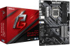
... ;a floppy disk containing the following steps to confirm your exit. Press Enter to install the Intel Rapid Storage Technology driver during text-mode phase). Select the volume size and press Enter. 8. Press Y to load support for mass storage device(s). 2. Setup will then be visible. 6. Select your controller from the list of Windows setup (during operating system setup: 1. Leave 13 7. Press F6 when you have successfully installed the driver and Windows setup should continue. Use the Floppy Configuration Utility...
... ;a floppy disk containing the following steps to confirm your exit. Press Enter to install the Intel Rapid Storage Technology driver during text-mode phase). Select the volume size and press Enter. 8. Press Y to load support for mass storage device(s). 2. Setup will then be visible. 6. Select your controller from the list of Windows setup (during operating system setup: 1. Leave 13 7. Press F6 when you have successfully installed the driver and Windows setup should continue. Use the Floppy Configuration Utility...

Intel Rapid Storage Guide
Page 16
... disk labeled Manufacturer-supplied hardware support disk into Drive A:, insert a floppy disk containing the following steps to install the Intel® Rapid Storage Technology driver using F6 when in AHCI/RAID mode In order to install an operating system onto a single Serial ATA hard drive when the system is in RAID mode or AHCI mode, the F6 installation method must be prompted with a screen asking you can use the Floppy Configuration Utility to install a third party SCSI or RAID driver. Use the following files...
... disk labeled Manufacturer-supplied hardware support disk into Drive A:, insert a floppy disk containing the following steps to install the Intel® Rapid Storage Technology driver using F6 when in AHCI/RAID mode In order to install an operating system onto a single Serial ATA hard drive when the system is in RAID mode or AHCI mode, the F6 installation method must be prompted with a screen asking you can use the Floppy Configuration Utility to install a third party SCSI or RAID driver. Use the following files...

RAID Installation Guide
Page 7
... installing the hard disk drives, please set SATA Mode Selection to save the configuration changes and exit setup. Go to Advanced Storage Configuration and set the necessary RAID items in your USB flash drive into a USB port B. Press to [RAID]. 2.3 Installing Windows® 10 64-bit With RAID Functions If you want to install Windows® 10 64-bit OS on your SATA / SATA2 / SATA3 HDDs with just one simple click in UEFI setup. STEP 2: Use ASRock Easy RAID Installer Easy RAID Installer can copy the RAID driver from a support...
... installing the hard disk drives, please set SATA Mode Selection to save the configuration changes and exit setup. Go to Advanced Storage Configuration and set the necessary RAID items in your USB flash drive into a USB port B. Press to [RAID]. 2.3 Installing Windows® 10 64-bit With RAID Functions If you want to install Windows® 10 64-bit OS on your SATA / SATA2 / SATA3 HDDs with just one simple click in UEFI setup. STEP 2: Use ASRock Easy RAID Installer Easy RAID Installer can copy the RAID driver from a support...

User Manual
Page 4
Contents Chapter 1 Introduction 1 1.1 Package Contents 1 1.2 Specifications 2 1.3 Motherboard Layout 7 1.4 I/O Panel 9 Chapter 2 Installation 10 2.1 Installing the CPU 11 2.2 Installing the CPU Fan and Heatsink 14 2.3 Installing Memory Modules (DIMM) 15 2.4 Expansion Slots (PCI Express Slots) 17 2.5 Jumpers Setup 18 2.6 Onboard Headers and Connectors 19 2.7 Post Status Checker 25 2.8 CrossFireXTM and Quad CrossFireXTM Operation Guide 26 2.8.1 Installing Two CrossFireXTM-Ready Graphics Cards 26 2.8.2 Driver Installation and Setup 28 2.9 M.2 WiFi/BT Module and ...
Contents Chapter 1 Introduction 1 1.1 Package Contents 1 1.2 Specifications 2 1.3 Motherboard Layout 7 1.4 I/O Panel 9 Chapter 2 Installation 10 2.1 Installing the CPU 11 2.2 Installing the CPU Fan and Heatsink 14 2.3 Installing Memory Modules (DIMM) 15 2.4 Expansion Slots (PCI Express Slots) 17 2.5 Jumpers Setup 18 2.6 Onboard Headers and Connectors 19 2.7 Post Status Checker 25 2.8 CrossFireXTM and Quad CrossFireXTM Operation Guide 26 2.8.1 Installing Two CrossFireXTM-Ready Graphics Cards 26 2.8.2 Driver Installation and Setup 28 2.9 M.2 WiFi/BT Module and ...
User Manual
Page 7
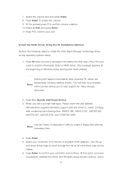
... BIOS setup. Chapter 4 contains the configuration guide of the software and utilities. In case any modifications of the motherboard and step-by-step installation guides. If you require technical support related to this documentation occur, the updated version will be updated, the content of this documentation, Chapter 1 and 2 contains the introduction of this motherboard, please visit our website for specific information about the model you for M.2 Sockets (Optional) • 1 x I/O Panel...
... BIOS setup. Chapter 4 contains the configuration guide of the software and utilities. In case any modifications of the motherboard and step-by-step installation guides. If you require technical support related to this documentation occur, the updated version will be updated, the content of this documentation, Chapter 1 and 2 contains the introduction of this motherboard, please visit our website for specific information about the model you for M.2 Sockets (Optional) • 1 x I/O Panel...
User Manual
Page 11
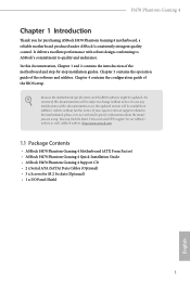
...1 x 24 pin ATX Power Connector • 1 x 8 pin 12V Power Connector • 1 x 4 pin 12V Power Connector • 1 x Front Panel Audio Connector • 1 x Thunderbolt AIC Connector (5-pin) (Supports ASRock Thunderbolt 3 AIC R2.0 Card only) • 2 x USB 2.0 Headers (Support 4 USB 2.0 ports) (Supports ESD Protection) • 2 x USB 3.2 Gen1 Headers (Support 4 USB 3.2 Gen1 ports) (Supports ESD Protection) BIOS Feature • AMI UEFI Legal BIOS with multilingual GUI support • ACPI 6.0 Compliant wake up events • SMBIOS 2.7 Support • CPU Core/Cache, GT, DRAM, PCH, VCCIO...
...1 x 24 pin ATX Power Connector • 1 x 8 pin 12V Power Connector • 1 x 4 pin 12V Power Connector • 1 x Front Panel Audio Connector • 1 x Thunderbolt AIC Connector (5-pin) (Supports ASRock Thunderbolt 3 AIC R2.0 Card only) • 2 x USB 2.0 Headers (Support 4 USB 2.0 ports) (Supports ESD Protection) • 2 x USB 3.2 Gen1 Headers (Support 4 USB 3.2 Gen1 ports) (Supports ESD Protection) BIOS Feature • AMI UEFI Legal BIOS with multilingual GUI support • ACPI 6.0 Compliant wake up events • SMBIOS 2.7 Support • CPU Core/Cache, GT, DRAM, PCH, VCCIO...

User Manual
Page 14
... Chassis/Water Pump Fan Connector (CHA_FAN4/WP) 18 SPI TPM Header (SPI_TPM_J1) 19 Power LED and Speaker Header (SPK_PLED1) 20 SATA3 Connector (SATA3_5) 21 SATA3 Connector (SATA3_4) 22 System Panel Header (PANEL1) 23 Chassis/Water Pump Fan Connector (CHA_FAN3/WP) 24 USB 3.2 Gen1 Header (USB3_5_6) 25 USB 2.0 Header (USB_5_6) 26 USB 2.0 Header (USB_3_4) 27 Addressable LED Header (ADDR_LED1) 28 RGB LED Header (RGB_LED1) 29 Front Panel Audio Header (HD_AUDIO1) 30 Clear CMOS Jumper (CLRMOS1) 31 Thunderbolt AIC Connector (TB1) 32 Chassis/Water Pump Fan Connector...
... Chassis/Water Pump Fan Connector (CHA_FAN4/WP) 18 SPI TPM Header (SPI_TPM_J1) 19 Power LED and Speaker Header (SPK_PLED1) 20 SATA3 Connector (SATA3_5) 21 SATA3 Connector (SATA3_4) 22 System Panel Header (PANEL1) 23 Chassis/Water Pump Fan Connector (CHA_FAN3/WP) 24 USB 3.2 Gen1 Header (USB3_5_6) 25 USB 2.0 Header (USB_5_6) 26 USB 2.0 Header (USB_3_4) 27 Addressable LED Header (ADDR_LED1) 28 RGB LED Header (RGB_LED1) 29 Front Panel Audio Header (HD_AUDIO1) 30 Clear CMOS Jumper (CLRMOS1) 31 Thunderbolt AIC Connector (TB1) 32 Chassis/Water Pump Fan Connector...

User Manual
Page 23
... slot) is used for PCI Express x1 lane width cards. PCIe Slot Configurations Single Graphics Card PCIE2 x16 PCIE4 N/A Two Graphics Cards in CrossFireXTM Mode x16 x4 For a better thermal environment, please connect a chassis fan to the motherboard's chassis fan connector (CHA_FAN1/WP, CHA_FAN2/WP, CHA_FAN3/WP or CHA_FAN4/WP) when using multiple graphics cards. H470 Phantom Gaming 4 2.4 Expansion Slots (PCI Express Slots) There are 5 PCI Express slots on the motherboard. Please read the documentation of the expansion card and make sure that the power supply is switched...
... slot) is used for PCI Express x1 lane width cards. PCIe Slot Configurations Single Graphics Card PCIE2 x16 PCIE4 N/A Two Graphics Cards in CrossFireXTM Mode x16 x4 For a better thermal environment, please connect a chassis fan to the motherboard's chassis fan connector (CHA_FAN1/WP, CHA_FAN2/WP, CHA_FAN3/WP or CHA_FAN4/WP) when using multiple graphics cards. H470 Phantom Gaming 4 2.4 Expansion Slots (PCI Express Slots) There are 5 PCI Express slots on the motherboard. Please read the documentation of the expansion card and make sure that the power supply is switched...
User Manual
Page 29
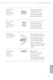
... (default slot). To use a 4-pin 4 1 ATX power supply, please plug it along Pin 1 and Pin 5. A TPM system also helps enhance network security, protects digital identities, and ensures platform integrity. 1 Please connect a Thunderbolt™ add-in only one orientation. English 23 SPI TPM Header (13-pin SPI_TPM_J1) (see p.7, No. 18) Thunderbolt AIC Connector (5-pin TB1) (see p.7, No. 2) This motherboard provides 8 5 an 8-pin ATX 12V power connector. H470 Phantom Gaming 4 ATX 12V Power Connector (8-pin ATX12V1) (see p.7, No. 1) ATX 12V Power Connector (4-pin ATX12V2...
... (default slot). To use a 4-pin 4 1 ATX power supply, please plug it along Pin 1 and Pin 5. A TPM system also helps enhance network security, protects digital identities, and ensures platform integrity. 1 Please connect a Thunderbolt™ add-in only one orientation. English 23 SPI TPM Header (13-pin SPI_TPM_J1) (see p.7, No. 18) Thunderbolt AIC Connector (5-pin TB1) (see p.7, No. 2) This motherboard provides 8 5 an 8-pin ATX 12V power connector. H470 Phantom Gaming 4 ATX 12V Power Connector (8-pin ATX12V1) (see p.7, No. 1) ATX 12V Power Connector (4-pin ATX12V2...

User Manual
Page 32
Download the drivers from the AMD's website: www.amd.com 3. CrossFire Bridge Step 2 Connect two graphics cards by installing a CrossFire Bridge on the CrossFire Bridge Interconnects on the slots. Please refer to AMD graphics card manuals for details.) English 26 2.8 CrossFireXTM and Quad CrossFireXTM Operation Guide This motherboard supports CrossFireXTM and Quad CrossFireXTM that are properly seated on the top of the graphics cards. (The CrossFire Bridge is recommended...
Download the drivers from the AMD's website: www.amd.com 3. CrossFire Bridge Step 2 Connect two graphics cards by installing a CrossFire Bridge on the CrossFire Bridge Interconnects on the slots. Please refer to AMD graphics card manuals for details.) English 26 2.8 CrossFireXTM and Quad CrossFireXTM Operation Guide This motherboard supports CrossFireXTM and Quad CrossFireXTM that are properly seated on the top of the graphics cards. (The CrossFire Bridge is recommended...
User Manual
Page 34
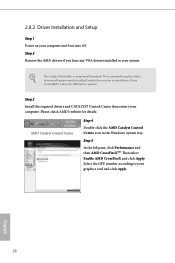
... Then select Enable AMD CrossFireX and click Apply. The Catalyst Uninstaller is an optional download. Step 5 In the left pane, click Performance and then AMD CrossFireXTM. Step 2 Remove the AMD drivers if you have any previously installed Catalyst drivers prior to uninstall any VGA drivers installed in the Windows® system tray. Please check AMD's website for AMD driver updates. We recommend using this utility to installation. 2.8.2 Driver Installation and Setup Step 1 Power on your...
... Then select Enable AMD CrossFireX and click Apply. The Catalyst Uninstaller is an optional download. Step 5 In the left pane, click Performance and then AMD CrossFireXTM. Step 2 Remove the AMD drivers if you have any previously installed Catalyst drivers prior to uninstall any VGA drivers installed in the Windows® system tray. Please check AMD's website for AMD driver updates. We recommend using this utility to installation. 2.8.2 Driver Installation and Setup Step 1 Power on your...
User Manual
Page 45
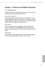
... your CD-ROM drive. If the Main Menu does not appear automatically, locate and double click on the file "ASRSETUP.EXE" in your system will be auto-detected and listed on a specific item then follow the order from top to bottom to your computer. Please click Install All or follow the installation wizard to display the menu. H470 Phantom Gaming 4 Chapter 3 Software and Utilities Operation 3.1 Installing Drivers The Support CD that...
... your CD-ROM drive. If the Main Menu does not appear automatically, locate and double click on the file "ASRSETUP.EXE" in your system will be auto-detected and listed on a specific item then follow the order from top to bottom to your computer. Please click Install All or follow the installation wizard to display the menu. H470 Phantom Gaming 4 Chapter 3 Software and Utilities Operation 3.1 Installing Drivers The Support CD that...

User Manual
Page 76
... if the system supports 64 bit PCI decoding). DMI Link Speed Configure DMI Slot Link Speed. PCIE1 Link Speed Select the link speed for overclocking. SR-IOV Support If system has SR-IOV capable PCIe Devices, this option Enables or Disables Single Root IO Virtualization Support. 4.6.2 Chipset Configuration Primary Graphics Adapter Select a primary VGA. Auto mode is optimizing for PCIE1. 70 English VT-d Intel® Virtualization Technology for Directed I/O helps your virtual machine monitor better utilize hardware by improving...
... if the system supports 64 bit PCI decoding). DMI Link Speed Configure DMI Slot Link Speed. PCIE1 Link Speed Select the link speed for overclocking. SR-IOV Support If system has SR-IOV capable PCIe Devices, this option Enables or Disables Single Root IO Virtualization Support. 4.6.2 Chipset Configuration Primary Graphics Adapter Select a primary VGA. Auto mode is optimizing for PCIE1. 70 English VT-d Intel® Virtualization Technology for Directed I/O helps your virtual machine monitor better utilize hardware by improving...

User Manual
Page 77
... all PCH PCIE devices. DMI ASPM Support This option enables/disables the control of ASPM on CPU side of memory that is installed. Share Memory Configure the size of the DMI Link. IGPU Multi-Monitor Select disable to disable the integrated graphics when an external graphics card is allocated to the integrated graphics processor when the system boots up. PCI Express Native Control Select Enable for PCIE2. H470 Phantom Gaming 4 PCIE2 Link Speed Select the link speed for enhanced PCI Express power saving in...
... all PCH PCIE devices. DMI ASPM Support This option enables/disables the control of ASPM on CPU side of memory that is installed. Share Memory Configure the size of the DMI Link. IGPU Multi-Monitor Select disable to disable the integrated graphics when an external graphics card is allocated to the integrated graphics processor when the system boots up. PCI Express Native Control Select Enable for PCIE2. H470 Phantom Gaming 4 PCIE2 Link Speed Select the link speed for enhanced PCI Express power saving in...

User Manual
Page 78
... panel HD audio. Onboard WAN Device Use this item to boot up when the power recovers. Turn On Onboard LED in the ACPI S5 state. Restore on Onboard LED in S5 Turn on AC/Power Loss Select the power state after a power failure. RGB LED This option enables/disables the RGB LED. 72 English Bluetooth Enable/disable the Bluetooth connectivity. Restore Onboard LED Default Restore Onboard LED default value. automatically disable it when a sound card is selected, the power will start to enable or disable the onboard WAN device. Deep Sleep Configure deep sleep mode...
... panel HD audio. Onboard WAN Device Use this item to boot up when the power recovers. Turn On Onboard LED in the ACPI S5 state. Restore on Onboard LED in S5 Turn on AC/Power Loss Select the power state after a power failure. RGB LED This option enables/disables the RGB LED. 72 English Bluetooth Enable/disable the Bluetooth connectivity. Restore Onboard LED Default Restore Onboard LED default value. automatically disable it when a sound card is selected, the power will start to enable or disable the onboard WAN device. Deep Sleep Configure deep sleep mode...

User Manual
Page 80
4.6.4 Intel(R) Thunderbolt Discrete Thunderbolt(TM) Support Enable or disable the Discrete Thunderbolt(TM) Support. Security Level This item allows you to allow booting from Bootable devices which are present behind Thunderbolt. Titan Ridge Workaround for OSUP Enable or disable Titan Ridge Workaround for the Thunderbolt ports. 74 English Thunderbolt Usb Support Enabled to allow booting from Usb devices which are present behind Thunderbolt. Thunderbolt Boot Support Enabled to choose a security level for OSUP.
4.6.4 Intel(R) Thunderbolt Discrete Thunderbolt(TM) Support Enable or disable the Discrete Thunderbolt(TM) Support. Security Level This item allows you to allow booting from Bootable devices which are present behind Thunderbolt. Titan Ridge Workaround for OSUP Enable or disable Titan Ridge Workaround for the Thunderbolt ports. 74 English Thunderbolt Usb Support Enabled to allow booting from Usb devices which are present behind Thunderbolt. Thunderbolt Boot Support Enabled to choose a security level for OSUP.
User Manual
Page 85
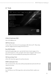
... system in RAID mode. Please setup network configuration before using UEFI Tech Service. Easy RAID Installer Easy RAID Installer helps you are having trouble with your USB storage device. After copying the drivers please change the SATA mode to update your UEFI. 79 English UEFI Tech Service Contact ASRock Tech Service if you to copy the RAID driver from the support CD to your PC. Instant Flash Save UEFI files in your USB storage device and run Instant Flash to RAID, then you Sanitize SSD, all user data...
... system in RAID mode. Please setup network configuration before using UEFI Tech Service. Easy RAID Installer Easy RAID Installer helps you are having trouble with your USB storage device. After copying the drivers please change the SATA mode to update your UEFI. 79 English UEFI Tech Service Contact ASRock Tech Service if you to copy the RAID driver from the support CD to your PC. Instant Flash Save UEFI files in your USB storage device and run Instant Flash to RAID, then you Sanitize SSD, all user data...
User Manual
Page 86
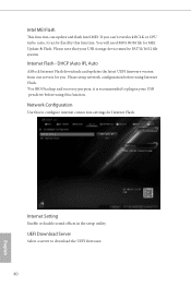
... Auto ASRock Internet Flash downloads and updates the latest UEFI firmware version from our servers for you can't overclock BCLK or CPU turbo ratio, it is recommended to plug in the setup utility. Please setup network configuration before using Internet Flash. *For BIOS backup and recovery purpose, it can update and flash Intel MEI. UEFI Download Server Select a server to configure internet connection settings for MEI Update & Flash. Network Configuration Use this function. Internet Flash - Internet Setting Enable or disable sound effects in your USB storage device must...
... Auto ASRock Internet Flash downloads and updates the latest UEFI firmware version from our servers for you can't overclock BCLK or CPU turbo ratio, it is recommended to plug in the setup utility. Please setup network configuration before using Internet Flash. *For BIOS backup and recovery purpose, it can update and flash Intel MEI. UEFI Download Server Select a server to configure internet connection settings for MEI Update & Flash. Network Configuration Use this function. Internet Flash - Internet Setting Enable or disable sound effects in your USB storage device must...

User Manual
Page 91
... Secure Boot. Supervisor Password Set or change the settings in the UEFI Setup Utility. Disable this section you may also clear the user password. H470 Phantom Gaming 4 4.9 Security Screen In this option to use discrete TPM Module. 85 English Leave it blank and press enter to remove the password. You may set or change the password for the system. Intel(R) Platform Trust Technology Enable/disable Intel PTT in ME. Secure Boot Use this item to remove the password. User Password Set or change the supervisor/user password...
... Secure Boot. Supervisor Password Set or change the settings in the UEFI Setup Utility. Disable this section you may also clear the user password. H470 Phantom Gaming 4 4.9 Security Screen In this option to use discrete TPM Module. 85 English Leave it blank and press enter to remove the password. You may set or change the password for the system. Intel(R) Platform Trust Technology Enable/disable Intel PTT in ME. Secure Boot Use this item to remove the password. User Password Set or change the supervisor/user password...


