
User Manual
Page 4
... 1 1.2 Specifications 2 1.3 Motherboard Layout 6 1.4 I/O Panel 8 Chapter 2 Installation 9 2.1 Installing the CPU 10 2.2 Installing the CPU Fan and Heatsink 13 2.3 Installing Memory Modules (SO-DIMM) 14 2.4 Jumpers Setup 15 2.5 Onboard Headers and Connectors 17 2.6 M.2 WiFi/BT Module Installation Guide 21 2.7 M.2_SSD (NGFF) Module Installation Guide 23 Chapter 3 Software and Utilities Operation 28 3.1 Installing Drivers 28 Chapter 4 UEFI SETUP UTILITY 29 4.1 Introduction 29 4.2 EZ Mode 30 4.3 Advanced Mode 31 4.3.1 UEFI Menu Bar 31 4.3.2 Navigation Keys 32...
... 1 1.2 Specifications 2 1.3 Motherboard Layout 6 1.4 I/O Panel 8 Chapter 2 Installation 9 2.1 Installing the CPU 10 2.2 Installing the CPU Fan and Heatsink 13 2.3 Installing Memory Modules (SO-DIMM) 14 2.4 Jumpers Setup 15 2.5 Onboard Headers and Connectors 17 2.6 M.2 WiFi/BT Module Installation Guide 21 2.7 M.2_SSD (NGFF) Module Installation Guide 23 Chapter 3 Software and Utilities Operation 28 3.1 Installing Drivers 28 Chapter 4 UEFI SETUP UTILITY 29 4.1 Introduction 29 4.2 EZ Mode 30 4.3 Advanced Mode 31 4.3.1 UEFI Menu Bar 31 4.3.2 Navigation Keys 32...

User Manual
Page 6
... (Optional) • 2 x Serial ATA (SATA) Data Cables (Optional) • 2 x SATA Power Cables (Optional) • 2 x Screws for purchasing H410TM-ITX motherboard. Chapter 4 contains the configuration guide of the motherboard and step-by-step installation guides. Because the motherboard specifications and the BIOS software might be updated, the content of the software and utilities. Chapter 3 contains the operation guide of this documentation, Chapter 1 and 2 contains the introduction of the BIOS setup. H410TM-ITX Chapter 1 Introduction Thank you for M.2 Sockets (M2*2) (Optional...
... (Optional) • 2 x Serial ATA (SATA) Data Cables (Optional) • 2 x SATA Power Cables (Optional) • 2 x Screws for purchasing H410TM-ITX motherboard. Chapter 4 contains the configuration guide of the motherboard and step-by-step installation guides. Because the motherboard specifications and the BIOS software might be updated, the content of the software and utilities. Chapter 3 contains the operation guide of this documentation, Chapter 1 and 2 contains the introduction of the BIOS setup. H410TM-ITX Chapter 1 Introduction Thank you for M.2 Sockets (M2*2) (Optional...

User Manual
Page 8
... power adapter) • 1 x Serial Port: COM • 2 x HDMI Ports: HDMI1 (Rear), HDMI2 (Internal) • 4 x USB 3.2 Gen1 Ports (Supports ESD Protection) • 1 x RJ-45 LAN Port with max. resolution up to 4K x 2K (4096x2160) @ 30Hz HDMI x 1 port (Rear) HDMI x 1 port (Internal) • Supports Auto Lip Sync, Deep Color (12bpc), xvYCC and HBR (High Bit Rate Audio) with HDMI 1.4 Port (Compliant HDMI monitor is required) • Supports LVDS with LED (ACT/LINK LED and SPEED LED) • HD Audio Jacks: Line out / Microphone English 3 H410TM-ITX Audio LAN...
... power adapter) • 1 x Serial Port: COM • 2 x HDMI Ports: HDMI1 (Rear), HDMI2 (Internal) • 4 x USB 3.2 Gen1 Ports (Supports ESD Protection) • 1 x RJ-45 LAN Port with max. resolution up to 4K x 2K (4096x2160) @ 30Hz HDMI x 1 port (Rear) HDMI x 1 port (Internal) • Supports Auto Lip Sync, Deep Color (12bpc), xvYCC and HBR (High Bit Rate Audio) with HDMI 1.4 Port (Compliant HDMI monitor is required) • Supports LVDS with LED (ACT/LINK LED and SPEED LED) • HD Audio Jacks: Line out / Microphone English 3 H410TM-ITX Audio LAN...

User Manual
Page 9
...x Internal Speaker Header (4-Pin) • 2 x SATA Power Connectors • 2 x USB 2.0 Headers (Support 4 USB 2.0 ports) (Supports ESD Protection) BIOS Feature • AMI UEFI Legal BIOS with GUI support • ACPI 6.0 Compliant wake up events • SMBIOS 2.7 Support Hardware Monitor • CPU Temperature Sensing • CPU Fan Tachometer • CPU Quiet Fan (Auto adjust chassis fan speed by CPU temperature) • CPU Fan Multi-Speed Control • CASE OPEN detection • Voltage monitoring: +12V, +5V, +3.3V, CPU Vcore OS • Microsoft® Windows® 10 64-bit...
...x Internal Speaker Header (4-Pin) • 2 x SATA Power Connectors • 2 x USB 2.0 Headers (Support 4 USB 2.0 ports) (Supports ESD Protection) BIOS Feature • AMI UEFI Legal BIOS with GUI support • ACPI 6.0 Compliant wake up events • SMBIOS 2.7 Support Hardware Monitor • CPU Temperature Sensing • CPU Fan Tachometer • CPU Quiet Fan (Auto adjust chassis fan speed by CPU temperature) • CPU Fan Multi-Speed Control • CASE OPEN detection • Voltage monitoring: +12V, +5V, +3.3V, CPU Vcore OS • Microsoft® Windows® 10 64-bit...

User Manual
Page 13
...! This jack accepts dual barrel plugs with support for either 4-pin ATX 19V power or DC-in power adapter, please use a 19V power adapter for the DC jack. ACT/LINK LED SPEED LED LAN Port Activity / Link LED Status Description Off Blinking On No Link Data Activity Link Speed LED Status Off Green Green Description 10Mbps connection 100Mbps connection 1Gbps connection ** Please use the onboard SATA power connector to the table below for HDDs. 8 English DELTA...
...! This jack accepts dual barrel plugs with support for either 4-pin ATX 19V power or DC-in power adapter, please use a 19V power adapter for the DC jack. ACT/LINK LED SPEED LED LAN Port Activity / Link LED Status Description Off Blinking On No Link Data Activity Link Speed LED Status Off Green Green Description 10Mbps connection 100Mbps connection 1Gbps connection ** Please use the onboard SATA power connector to the table below for HDDs. 8 English DELTA...

User Manual
Page 14
... static electricity to the motherboard's components, NEVER place your chassis to ensure that comes with the components. • When placing screws to secure the motherboard to unplug the power cord before you install the motherboard, study the configuration of the following precautions before installing or removing the motherboard. H410TM-ITX Chapter 2 Installation This is a Thin Mini-ITX form factor motherboard. Pre-installation Precautions Take note of...
... static electricity to the motherboard's components, NEVER place your chassis to ensure that comes with the components. • When placing screws to secure the motherboard to unplug the power cord before you install the motherboard, study the configuration of the following precautions before installing or removing the motherboard. H410TM-ITX Chapter 2 Installation This is a Thin Mini-ITX form factor motherboard. Pre-installation Precautions Take note of...

User Manual
Page 20
... chassis intrusion status. Please adjust the BIOS option "Clear Status" to default setup, please turn off the computer and unplug the power cord from the power supply. Please be noted that the password, date, time, and user default profile will be detected. H410TM-ITX 2.4 Jumpers Setup The illustration shows how jumpers are setup. If no jumper cap is placed on the pins, the jumper is "Short". When the jumper cap is placed on the pins...
... chassis intrusion status. Please adjust the BIOS option "Clear Status" to default setup, please turn off the computer and unplug the power cord from the power supply. Please be noted that the password, date, time, and user default profile will be detected. H410TM-ITX 2.4 Jumpers Setup The illustration shows how jumpers are setup. If no jumper cap is placed on the pins, the jumper is "Short". When the jumper cap is placed on the pins...

User Manual
Page 22
... and negative pins before connecting the cables. You may differ by chassis. When connecting your system using the power button. System Panel Header (9-pin PANEL1) (see p.6, No. 17) PLED+ PLEDPWRBTN# GND 1 GND RESET# GND HDLEDHDLED+ Connect the power button, reset button and system status indicator on the chassis to this header, make sure the wire assignments and the pin assignments are NOT jumpers. HDLED (Hard Drive Activity LED): Connect to the pin assignments below. H410TM-ITX 2.5 Onboard Headers and Connectors Onboard headers and connectors are...
... and negative pins before connecting the cables. You may differ by chassis. When connecting your system using the power button. System Panel Header (9-pin PANEL1) (see p.6, No. 17) PLED+ PLEDPWRBTN# GND 1 GND RESET# GND HDLEDHDLED+ Connect the power button, reset button and system status indicator on the chassis to this header, make sure the wire assignments and the pin assignments are NOT jumpers. HDLED (Hard Drive Activity LED): Connect to the pin assignments below. H410TM-ITX 2.5 Onboard Headers and Connectors Onboard headers and connectors are...

User Manual
Page 23
... connect SATA power cables. 1 USB 2.0 Headers (9-pin USB2_1_2) (see p.6, No. 7) (9-pin USB2_3_4) (see p.6, No. 6) SATA_1 SATA_2 These two SATA3 connectors support SATA data cable for J_SENSE OUT2_R connecting audio devices MIC2_R to the front audio panel. Serial ATA3 Connectors (SATA_1: see p.6, No. 3) (SATA_2: see p.6, No. 8) USB_PWR PP+ GND DUMMY 1 GND P+ PUSB_PWR There are two headers on this header. Front Panel Audio Header OUT_RET (9-pin HD_AUDIO1) (see p.6, No. 18) 1 R+ - - +L Please connect the chassis speaker to this motherboard. Internal Speaker Header...
... connect SATA power cables. 1 USB 2.0 Headers (9-pin USB2_1_2) (see p.6, No. 7) (9-pin USB2_3_4) (see p.6, No. 6) SATA_1 SATA_2 These two SATA3 connectors support SATA data cable for J_SENSE OUT2_R connecting audio devices MIC2_R to the front audio panel. Serial ATA3 Connectors (SATA_1: see p.6, No. 3) (SATA_2: see p.6, No. 8) USB_PWR PP+ GND DUMMY 1 GND P+ PUSB_PWR There are two headers on this header. Front Panel Audio Header OUT_RET (9-pin HD_AUDIO1) (see p.6, No. 18) 1 R+ - - +L Please connect the chassis speaker to this motherboard. Internal Speaker Header...

User Manual
Page 24
... our manual and chassis manual to MIC2_L. To activate the front mic, go to OUT2_L. CPU Fan Connectors (4-pin CPU_FAN1) (see p.6, No. 14) (4-pin CPU_FAN2) (see p.6, No. 9) Please connect an ATX +19V 19V power supply to Pin 1-3. Please follow the instructions in the Realtek Control panel and adjust "Recording Volume". C. D. E. B. MIC_RET and OUT_RET are for the AC'97 audio panel. H410TM-ITX 1. If you plan to connect a 3-Pin CPU fan, please connect it to connect them...
... our manual and chassis manual to MIC2_L. To activate the front mic, go to OUT2_L. CPU Fan Connectors (4-pin CPU_FAN1) (see p.6, No. 14) (4-pin CPU_FAN2) (see p.6, No. 9) Please connect an ATX +19V 19V power supply to Pin 1-3. Please follow the instructions in the Realtek Control panel and adjust "Recording Volume". C. D. E. B. MIC_RET and OUT_RET are for the AC'97 audio panel. H410TM-ITX 1. If you plan to connect a 3-Pin CPU fan, please connect it to connect them...

User Manual
Page 26
The M.2 Socket (Key E) supports type 2230 WiFi/BT module. Please be used. A English A 20o 21 Installing the WiFi/BT module Step 1 Prepare a type 2230 WiFi/BT module and the screw. A Step 3 Gently insert the WiFi/BT module into the M.2 slot. PCB Length: 3cm Module Type: Type2230 Step 2 Find the nut location to be aware that aims to replace mPCIe and mSATA. H410TM-ITX 2.6 M.2 WiFi/BT Module Installation Guide The M.2, also known as the Next Generation Form Factor (NGFF), is a small size and versatile card edge connector that the module only fits in one orientation.
The M.2 Socket (Key E) supports type 2230 WiFi/BT module. Please be used. A English A 20o 21 Installing the WiFi/BT module Step 1 Prepare a type 2230 WiFi/BT module and the screw. A Step 3 Gently insert the WiFi/BT module into the M.2 slot. PCB Length: 3cm Module Type: Type2230 Step 2 Find the nut location to be aware that aims to replace mPCIe and mSATA. H410TM-ITX 2.6 M.2 WiFi/BT Module Installation Guide The M.2, also known as the Next Generation Form Factor (NGFF), is a small size and versatile card edge connector that the module only fits in one orientation.
User Manual
Page 33
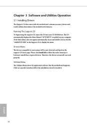
..., the drivers you install can work properly. Click on the support CD driver page. Chapter 3 Software and Utilities Operation 3.1 Installing Drivers The Support CD that comes with the motherboard contains necessary drivers and useful utilities that the motherboard supports. If the Main Menu does not appear automatically, locate and double click on the file "ASRSETUP.EXE" in your CD-ROM drive. Utilities Menu The Utilities Menu shows the application software that enhance the motherboard's features. Running The Support CD...
..., the drivers you install can work properly. Click on the support CD driver page. Chapter 3 Software and Utilities Operation 3.1 Installing Drivers The Support CD that comes with the motherboard contains necessary drivers and useful utilities that the motherboard supports. If the Main Menu does not appear automatically, locate and double click on the file "ASRSETUP.EXE" in your CD-ROM drive. Utilities Menu The Utilities Menu shows the application software that enhance the motherboard's features. Running The Support CD...

User Manual
Page 40
... frequency. This is only supported with processors with Config TDP support. H410TM-ITX Boot Performance Mode Select the performance state that implment the Intel Thermal Velocity Boost (TVB) feature. Long Duration Maintained Configure the period of time until the CPU ratio is lowered when the Long Duration Power Limit is exceeded, the CPU ratio will set before OS handoff. Intel Speed Shift Technology Enable/Disable Intel Speed Shift Technology support. FCLK Frequency Configure the FCLK Frequency...
... frequency. This is only supported with processors with Config TDP support. H410TM-ITX Boot Performance Mode Select the performance state that implment the Intel Thermal Velocity Boost (TVB) feature. Long Duration Maintained Configure the period of time until the CPU ratio is lowered when the Long Duration Power Limit is exceeded, the CPU ratio will set before OS handoff. Intel Speed Shift Technology Enable/Disable Intel Speed Shift Technology support. FCLK Frequency Configure the FCLK Frequency...

User Manual
Page 50
... your virtual machine monitor better utilize hardware by improving application compatibility and reliability, and providing additional levels of the DMI Link. 45 English PCH PCIE ASPM Support This option enables/disables the ASPM support for all PCH PCIE devices. 4.6.2 Chipset Configuration H410TM-ITX VT-d Intel® Virtualization Technology for PCIE1. DMI ASPM Support This option enables/disables the control of ASPM on CPU side of manageability, security, isolation, and I/O performance. PCI Express Native Control Select Enable for overclocking. Auto mode is...
... your virtual machine monitor better utilize hardware by improving application compatibility and reliability, and providing additional levels of the DMI Link. 45 English PCH PCIE ASPM Support This option enables/disables the ASPM support for all PCH PCIE devices. 4.6.2 Chipset Configuration H410TM-ITX VT-d Intel® Virtualization Technology for PCIE1. DMI ASPM Support This option enables/disables the control of ASPM on CPU side of manageability, security, isolation, and I/O performance. PCI Express Native Control Select Enable for overclocking. Auto mode is...

User Manual
Page 51
... graphics processor when the system boots up when the power recovers. Restore on AC/Power Loss Select the power state after a power failure. PCH DMI ASPM Support This option enables/disables the ASPM support for Port 80 debug. 46 English Set to Auto to enable or disable the onboard WAN device. Deep Sleep Configure deep sleep mode for the onboard digital outputs. Serial Port/UART Switch Select Serial Port or UART for all PCH DMI devices. BT Control Enable/disable the Bluetooth connectivity. WAN Radio Enable/disable...
... graphics processor when the system boots up when the power recovers. Restore on AC/Power Loss Select the power state after a power failure. PCH DMI ASPM Support This option enables/disables the ASPM support for Port 80 debug. 46 English Set to Auto to enable or disable the onboard WAN device. Deep Sleep Configure deep sleep mode for the onboard digital outputs. Serial Port/UART Switch Select Serial Port or UART for all PCH DMI devices. BT Control Enable/disable the Bluetooth connectivity. WAN Radio Enable/disable...

User Manual
Page 55
The XHCI ownership change should be claimed by XHCI driver. 50 English If you encounter USB compatibility issues it is a workaround for USB 2.0 devices. XHCI Hand-off This is recommended to support USB devices under the UEFI setup and Windows/Linux operating systems only. Select UEFI Setup Only to disable legacy USB support. 4.6.6 USB Configuration Legacy USB Support Enable or disable Legacy OS Support for OSes without XHCI hand-off support.
The XHCI ownership change should be claimed by XHCI driver. 50 English If you encounter USB compatibility issues it is a workaround for USB 2.0 devices. XHCI Hand-off This is recommended to support USB devices under the UEFI setup and Windows/Linux operating systems only. Select UEFI Setup Only to disable legacy USB support. 4.6.6 USB Configuration Legacy USB Support Enable or disable Legacy OS Support for OSes without XHCI hand-off support.

User Manual
Page 56
... reboot during restart in order to change State of your connected TPM module. Security Device Support Use this item to enable or disable BIOS support for the Security Device. 4.6.7 Trusted Computing H410TM-ITX NOTE: Options vary depending on the version of the Device. SHA-1 PCR Bank Use this item to enable or disable SHA-1 PCR Bank. Platform Hierarchy Use this item to enable or disable Platform Hierarchy. Pending Operation Schedule an...
... reboot during restart in order to change State of your connected TPM module. Security Device Support Use this item to enable or disable BIOS support for the Security Device. 4.6.7 Trusted Computing H410TM-ITX NOTE: Options vary depending on the version of the Device. SHA-1 PCR Bank Use this item to enable or disable SHA-1 PCR Bank. Platform Hierarchy Use this item to enable or disable Platform Hierarchy. Pending Operation Schedule an...

User Manual
Page 58
...), Auto ASRock Internet Flash downloads and updates the latest UEFI firmware version from our servers for you Sanitize SSD, all user data will be permanently destroyed on the SSD and cannot be recovered. 4.7 Tools H410TM-ITX SSD Secure Erase Tool All the SSD's listed that supports Secure Erase function. Internet Flash - Please setup network configuration before using Internet Flash. *For BIOS backup and recovery purpose, it is recommended to update your USB pen drive...
...), Auto ASRock Internet Flash downloads and updates the latest UEFI firmware version from our servers for you Sanitize SSD, all user data will be permanently destroyed on the SSD and cannot be recovered. 4.7 Tools H410TM-ITX SSD Secure Erase Tool All the SSD's listed that supports Secure Erase function. Internet Flash - Please setup network configuration before using Internet Flash. *For BIOS backup and recovery purpose, it is recommended to update your USB pen drive...

User Manual
Page 59
Internet Setting Enable or disable sound effects in the setup utility. Network Configuration Use this to download the UEFI firmware. 54 English UEFI Download Server Select a server to configure internet connection settings for Internet Flash.
Internet Setting Enable or disable sound effects in the setup utility. Network Configuration Use this to download the UEFI firmware. 54 English UEFI Download Server Select a server to configure internet connection settings for Internet Flash.

User Manual
Page 62
... enter to remove the password. Intel(R) Platform Trust Technology Enable/disable Intel PTT in the UEFI Setup Utility. Secure Boot Use this item to change the password for the system. Only the administrator has authority to enable or disable support for the user account. Disable this option to change the password for Secure Boot. H410TM-ITX 4.9 Security Screen In this section you may also clear the user password. You may set or change the supervisor/user password for the administrator account. User Password Set or change...
... enter to remove the password. Intel(R) Platform Trust Technology Enable/disable Intel PTT in the UEFI Setup Utility. Secure Boot Use this item to change the password for the system. Only the administrator has authority to enable or disable support for the user account. Disable this option to change the password for Secure Boot. H410TM-ITX 4.9 Security Screen In this section you may also clear the user password. You may set or change the supervisor/user password for the administrator account. User Password Set or change...


