
User Manual
Page 4
...1.2 Specifications 2 1.3 Motherboard Layout 6 1.4 I/O Panel 10 Chapter 2 Installation 12 2.1 Installing the CPU 13 2.2 Installing the CPU Fan and Heatsink 16 2.3 Installing Memory Modules (DIMM) 17 2.4 Expansion Slots (PCI and PCI Express Slots) 19 2.5 Jumpers Setup 20 2.6 Onboard Headers and Connectors 21 2.7 M.2_SSD (NGFF) Module Installation Guide 25 Chapter 3 Software and Utilities Operation 28 3.1 Installing Drivers 28 3.2 ASRock Motherboard Utility (A-Tuning) 29 3.2.1 Installing ASRock Motherboard Utility (A-Tuning) 29 3.2.2 Using ASRock Motherboard Utility...
...1.2 Specifications 2 1.3 Motherboard Layout 6 1.4 I/O Panel 10 Chapter 2 Installation 12 2.1 Installing the CPU 13 2.2 Installing the CPU Fan and Heatsink 16 2.3 Installing Memory Modules (DIMM) 17 2.4 Expansion Slots (PCI and PCI Express Slots) 19 2.5 Jumpers Setup 20 2.6 Onboard Headers and Connectors 21 2.7 M.2_SSD (NGFF) Module Installation Guide 25 Chapter 3 Software and Utilities Operation 28 3.1 Installing Drivers 28 3.2 ASRock Motherboard Utility (A-Tuning) 29 3.2.1 Installing ASRock Motherboard Utility (A-Tuning) 29 3.2.2 Using ASRock Motherboard Utility...
User Manual
Page 6
...; ASRock H410M-HDVP / H410M-HDVP2 Quick Installation Guide • ASRock H410M-HDVP / H410M-HDVP2 Support CD • 2 x Serial ATA (SATA) Data Cables (Optional) • 1 x Screw for purchasing ASRock H410M-HDVP / H410M-HDVP2 motherboard, a reliable motherboard produced under ASRock's consistently stringent quality control. It delivers excellent performance with robust design conforming to ASRock's commitment to this documentation, Chapter 1 and 2 contains the introduction of the BIOS setup. In this motherboard, please visit our website for specific information about the model...
...; ASRock H410M-HDVP / H410M-HDVP2 Quick Installation Guide • ASRock H410M-HDVP / H410M-HDVP2 Support CD • 2 x Serial ATA (SATA) Data Cables (Optional) • 1 x Screw for purchasing ASRock H410M-HDVP / H410M-HDVP2 motherboard, a reliable motherboard produced under ASRock's consistently stringent quality control. It delivers excellent performance with robust design conforming to ASRock's commitment to this documentation, Chapter 1 and 2 contains the introduction of the BIOS setup. In this motherboard, please visit our website for specific information about the model...

User Manual
Page 8
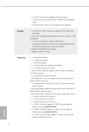
...; Supports HDMI 1.4 with HDMI 1.4 Port Audio • 7.1 CH HD Audio (Realtek ALC887 Audio Codec) • Supports Surge Protection LAN • PCIE x1 Gigabit LAN 10/100/1000 Mb/s • Realtek RTL8111GN • Supports Wake-On-LAN • Supports Lightning/ESD Protection • Supports Energy Efficient Ethernet 802.3az • Supports PXE Rear Panel I/O • 1 x PS/2 Mouse Port • 1 x PS/2 Keyboard Port • 1 x Serial Port: COM2 • 1 x D-Sub Port • 1 x DVI-D Port • 1 x HDMI Port • 4 x USB 2.0 Ports (Supports ESD Protection) (H410M...
...; Supports HDMI 1.4 with HDMI 1.4 Port Audio • 7.1 CH HD Audio (Realtek ALC887 Audio Codec) • Supports Surge Protection LAN • PCIE x1 Gigabit LAN 10/100/1000 Mb/s • Realtek RTL8111GN • Supports Wake-On-LAN • Supports Lightning/ESD Protection • Supports Energy Efficient Ethernet 802.3az • Supports PXE Rear Panel I/O • 1 x PS/2 Mouse Port • 1 x PS/2 Keyboard Port • 1 x Serial Port: COM2 • 1 x D-Sub Port • 1 x DVI-D Port • 1 x HDMI Port • 4 x USB 2.0 Ports (Supports ESD Protection) (H410M...
User Manual
Page 9
... AHCI and Hot Plug* * If M2_1 is occupied by a SATA-type M.2 device, SATA3_3 will be disabled. • 1 x M.2 Socket (M2_1), supports M Key type 2230/2242/2260/2280 M.2 SATA3 6.0 Gb/s module and M.2 PCI Express module up to Gen3 x2 (16 Gb/s)** ** Supports NVMe SSD as boot disks ** Supports ASRock U.2 Kit Connector • 1 x Print Port Header • 1 x COM Port Header • 1 x SPI TPM Header • 1 x Chassis Intrusion and Speaker Header • 1 x CPU Fan Connector (4-pin) * The CPU Fan Connector supports the CPU fan of maximum 1A (12W) fan power. • 1 x Chassis Fan Connector...
... AHCI and Hot Plug* * If M2_1 is occupied by a SATA-type M.2 device, SATA3_3 will be disabled. • 1 x M.2 Socket (M2_1), supports M Key type 2230/2242/2260/2280 M.2 SATA3 6.0 Gb/s module and M.2 PCI Express module up to Gen3 x2 (16 Gb/s)** ** Supports NVMe SSD as boot disks ** Supports ASRock U.2 Kit Connector • 1 x Print Port Header • 1 x COM Port Header • 1 x SPI TPM Header • 1 x Chassis Intrusion and Speaker Header • 1 x CPU Fan Connector (4-pin) * The CPU Fan Connector supports the CPU fan of maximum 1A (12W) fan power. • 1 x Chassis Fan Connector...

User Manual
Page 10
... components and devices of your own risk and expense. H410M-HDVP H410M-HDVP2 BIOS Feature Hardware Monitor OS Certifications • AMI UEFI Legal BIOS with overclocking, including adjusting the setting in the BIOS, applying Untied Overclocking Technology, or using third-party overclocking tools. It should be done at your system. ture): CPU, Chassis, Chassis/Water Pump Fans • Fan Multi-Speed Control: CPU, Chassis, Chassis/Water Pump Fans • CASE OPEN detection • CPU Core, DRAM, PCH, VCCSA Voltage Multi-adjustment...
... components and devices of your own risk and expense. H410M-HDVP H410M-HDVP2 BIOS Feature Hardware Monitor OS Certifications • AMI UEFI Legal BIOS with overclocking, including adjusting the setting in the BIOS, applying Untied Overclocking Technology, or using third-party overclocking tools. It should be done at your system. ture): CPU, Chassis, Chassis/Water Pump Fans • Fan Multi-Speed Control: CPU, Chassis, Chassis/Water Pump Fans • CASE OPEN detection • CPU Core, DRAM, PCH, VCCSA Voltage Multi-adjustment...

User Manual
Page 12
...) 2 CPU Fan Connector (CPU_FAN1) 3 2 x 288-pin DDR4 DIMM Slots (DDR4_A1, DDR4_B1) 4 ATX Power Connector (ATXPWR1) 5 USB 3.2 Gen1 Header (USB3_2_3) 6 SATA3 Connector (SATA3_3) 7 SATA3 Connector (SATA3_2) 8 SATA3 Connector (SATA3_0) 9 SATA3 Connector (SATA3_1) 10 Clear CMOS Jumper (CLRMOS1) 11 System Panel Header (PANEL1) 12 Chassis Fan Connector (CHA_FAN2) 13 SPI TPM Header (SPI_TPM_J1) 14 USB 2.0 Header (USB_4_5) 15 Chassis Intrusion and Speaker Header (SPK_CI1) 16 Print Port Header (LPT1) 17 COM Port Header (COM2) 18 Chassis/Water Pump Fan Connector (CHA_FAN1/WP) 19 Front Panel Audio Header...
...) 2 CPU Fan Connector (CPU_FAN1) 3 2 x 288-pin DDR4 DIMM Slots (DDR4_A1, DDR4_B1) 4 ATX Power Connector (ATXPWR1) 5 USB 3.2 Gen1 Header (USB3_2_3) 6 SATA3 Connector (SATA3_3) 7 SATA3 Connector (SATA3_2) 8 SATA3 Connector (SATA3_0) 9 SATA3 Connector (SATA3_1) 10 Clear CMOS Jumper (CLRMOS1) 11 System Panel Header (PANEL1) 12 Chassis Fan Connector (CHA_FAN2) 13 SPI TPM Header (SPI_TPM_J1) 14 USB 2.0 Header (USB_4_5) 15 Chassis Intrusion and Speaker Header (SPK_CI1) 16 Print Port Header (LPT1) 17 COM Port Header (COM2) 18 Chassis/Water Pump Fan Connector (CHA_FAN1/WP) 19 Front Panel Audio Header...

User Manual
Page 14
... 1 ATX 12V Power Connector (ATX12V1) 2 CPU Fan Connector (CPU_FAN1) 3 2 x 288-pin DDR4 DIMM Slots (DDR4_A1, DDR4_B1) 4 ATX Power Connector (ATXPWR1) 5 USB 3.2 Gen1 Header (USB3_2_3) 6 SATA3 Connector (SATA3_3) 7 SATA3 Connector (SATA3_2) 8 SATA3 Connector (SATA3_0) 9 SATA3 Connector (SATA3_1) 10 Clear CMOS Jumper (CLRMOS1) 11 System Panel Header (PANEL1) 12 Chassis Fan Connector (CHA_FAN2) 13 SPI TPM Header (SPI_TPM_J1) 14 USB 2.0 Header (USB_6_7) 15 USB 2.0 Header (USB_4_5) 16 Chassis Intrusion and Speaker Header (SPK_CI1) 17 Print Port Header (LPT1) 18 COM Port Header (COM2) 19 Chassis/Water...
... 1 ATX 12V Power Connector (ATX12V1) 2 CPU Fan Connector (CPU_FAN1) 3 2 x 288-pin DDR4 DIMM Slots (DDR4_A1, DDR4_B1) 4 ATX Power Connector (ATXPWR1) 5 USB 3.2 Gen1 Header (USB3_2_3) 6 SATA3 Connector (SATA3_3) 7 SATA3 Connector (SATA3_2) 8 SATA3 Connector (SATA3_0) 9 SATA3 Connector (SATA3_1) 10 Clear CMOS Jumper (CLRMOS1) 11 System Panel Header (PANEL1) 12 Chassis Fan Connector (CHA_FAN2) 13 SPI TPM Header (SPI_TPM_J1) 14 USB 2.0 Header (USB_6_7) 15 USB 2.0 Header (USB_4_5) 16 Chassis Intrusion and Speaker Header (SPK_CI1) 17 Print Port Header (LPT1) 18 COM Port Header (COM2) 19 Chassis/Water...
User Manual
Page 22
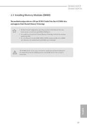
H410M-HDVP H410M-HDVP2 2.3 Installing Memory Modules (DIMM) This motherboard provides two 288-pin DDR4 (Double Data Rate 4) DIMM slots, and supports Dual Channel Memory Technology. 1. otherwise, this motherboard and DIMM may be damaged. The DIMM only fits in one memory module installed. 3. It will cause permanent damage to the motherboard and the DIMM if you always need to install identical (the same brand, speed, size and chip-type) DDR4 DIMM pairs. 2. It...
H410M-HDVP H410M-HDVP2 2.3 Installing Memory Modules (DIMM) This motherboard provides two 288-pin DDR4 (Double Data Rate 4) DIMM slots, and supports Dual Channel Memory Technology. 1. otherwise, this motherboard and DIMM may be damaged. The DIMM only fits in one memory module installed. 3. It will cause permanent damage to the motherboard and the DIMM if you always need to install identical (the same brand, speed, size and chip-type) DDR4 DIMM pairs. 2. It...

User Manual
Page 24
... 32-bit PCI interface. PCI slot: The PCI1 slot is used for PCI Express x16 lane width graphics cards. PCIE3 (PCIe 3.0 x1 slot) is used for PCI Express x1 lane width cards. PCIE2 (PCIe 3.0 x1 slot) is used to install expansion cards that the power supply is switched off or the power cord is unplugged. H410M-HDVP H410M-HDVP2 2.4 Expansion Slots (PCI and PCI Express Slots) There are 1 PCI slot and 3 PCI Express slots on the motherboard. PCIe slots: PCIE1 (PCIe 3.0 x16 slot) is used for the card before you start the installation. Before installing an expansion card, please...
... 32-bit PCI interface. PCI slot: The PCI1 slot is used for PCI Express x16 lane width graphics cards. PCIE3 (PCIe 3.0 x1 slot) is used for PCI Express x1 lane width cards. PCIE2 (PCIe 3.0 x1 slot) is used to install expansion cards that the power supply is switched off or the power cord is unplugged. H410M-HDVP H410M-HDVP2 2.4 Expansion Slots (PCI and PCI Express Slots) There are 1 PCI slot and 3 PCI Express slots on the motherboard. PCIe slots: PCIE1 (PCIe 3.0 x16 slot) is used for the card before you start the installation. Before installing an expansion card, please...

User Manual
Page 25
... BIOS option "Clear Status" to remove the jumper cap after clearing the CMOS. 2.5 Jumpers Setup The illustration shows how jumpers are setup. English 20 Clear CMOS Jumper (CLRMOS1) (see p.6, 8, No. 10) 2-pin Jumper Short: Clear CMOS Open: Default CLRMOS1 allows you do the clear-CMOS action. To clear and reset the system parameters to default setup, please turn off the computer and unplug the power cord, then use a jumper cap to clear the data in CMOS includes system setup information such as system password...
... BIOS option "Clear Status" to remove the jumper cap after clearing the CMOS. 2.5 Jumpers Setup The illustration shows how jumpers are setup. English 20 Clear CMOS Jumper (CLRMOS1) (see p.6, 8, No. 10) 2-pin Jumper Short: Clear CMOS Open: Default CLRMOS1 allows you do the clear-CMOS action. To clear and reset the system parameters to default setup, please turn off the computer and unplug the power cord, then use a jumper cap to clear the data in CMOS includes system setup information such as system password...

User Manual
Page 26
... header. 21 English Chassis Intrusion and Speaker Header (7-pin SPK_CI1) (see p.6, 8, No. 11) PLED+ PLEDPWRBTN# GND 1 GND RESET# GND HDLEDHDLED+ Connect the power button, reset button and system status indicator on when the system is in S1/S3 sleep state. H410M-HDVP H410M-HDVP2 2.6 Onboard Headers and Connectors Onboard headers and connectors are matched correctly. The front panel design may configure the way to the pin assignments below. HDLED (Hard Drive Activity LED): Connect to this header according to turn...
... header. 21 English Chassis Intrusion and Speaker Header (7-pin SPK_CI1) (see p.6, 8, No. 11) PLED+ PLEDPWRBTN# GND 1 GND RESET# GND HDLEDHDLED+ Connect the power button, reset button and system status indicator on when the system is in S1/S3 sleep state. H410M-HDVP H410M-HDVP2 2.6 Onboard Headers and Connectors Onboard headers and connectors are matched correctly. The front panel design may configure the way to the pin assignments below. HDLED (Hard Drive Activity LED): Connect to this header according to turn...

User Manual
Page 27
.... 6) SATA3_1 SATA3_3 SATA3_0 SATA3_2 These four SATA3 connectors support SATA data cables for connecting audio devices to the front audio panel. 1. USB 2.0 Headers (9-pin USB_4_5) (see p.6, No. 14 or p.8, No. 15) (9-pin USB_6_7) (see p.6, 8, No. 5) Vbus IntA_PA_SSRXIntA_PA_SSRX+ GND IntA_PA_SSTXIntA_PA_SSTX+ GND IntA_PA_DIntA_PA_D+ Vbus IntA_PB_SSRXIntA_PB_SSRX+ GND IntA_PB_SSTXIntA_PB_SSTX+ GND IntA_PB_DIntA_PB_D+ Dummy 1 There is one header on H410M-HDVP and two headers on H410MHDVP2. Front Panel Audio Header (9-pin HD_AUDIO1) (see p.6, No. 19 or p.8, No...
.... 6) SATA3_1 SATA3_3 SATA3_0 SATA3_2 These four SATA3 connectors support SATA data cables for connecting audio devices to the front audio panel. 1. USB 2.0 Headers (9-pin USB_4_5) (see p.6, No. 14 or p.8, No. 15) (9-pin USB_6_7) (see p.6, 8, No. 5) Vbus IntA_PA_SSRXIntA_PA_SSRX+ GND IntA_PA_SSTXIntA_PA_SSTX+ GND IntA_PA_DIntA_PA_D+ Vbus IntA_PB_SSRXIntA_PB_SSRX+ GND IntA_PB_SSTXIntA_PB_SSTX+ GND IntA_PB_DIntA_PB_D+ Dummy 1 There is one header on H410M-HDVP and two headers on H410MHDVP2. Front Panel Audio Header (9-pin HD_AUDIO1) (see p.6, No. 19 or p.8, No...

User Manual
Page 28
... PCIe power cable to connect a 3-Pin CPU fan, please connect it along Pin 1 and Pin 5. *Warning: Please make sure that the power cable connected is for the CPU and not the graphics card. To use a 20-pin ATX power supply, please plug it to the ground pin. ATX Power Connector (24-pin ATXPWR1) (see p.6, 8, No. 12) GND +12V CHA_FAN_SPEED FAN_SPEED_CONTROL 1 2 3 4 Please connect fan cables to the fan connector and match the black wire to Pin 1-3. Chassis Fan Connector (4-pin CHA_FAN2) (see p.6, 8, No. 4) 12 24 1 13 This motherboard provides a 24-pin ATX power...
... PCIe power cable to connect a 3-Pin CPU fan, please connect it along Pin 1 and Pin 5. *Warning: Please make sure that the power cable connected is for the CPU and not the graphics card. To use a 20-pin ATX power supply, please plug it to the ground pin. ATX Power Connector (24-pin ATXPWR1) (see p.6, 8, No. 12) GND +12V CHA_FAN_SPEED FAN_SPEED_CONTROL 1 2 3 4 Please connect fan cables to the fan connector and match the black wire to Pin 1-3. Chassis Fan Connector (4-pin CHA_FAN2) (see p.6, 8, No. 4) 12 24 1 13 This motherboard provides a 24-pin ATX power...
User Manual
Page 33
... CD-ROM drive. If the Main Menu does not appear automatically, locate and double click on a specific item then follow the order from top to bottom to display the menu. Click on the file "ASRSETUP.EXE" in your computer. Utilities Menu The Utilities Menu shows the application software that enhance the motherboard's features. Chapter 3 Software and Utilities Operation 3.1 Installing Drivers The Support CD that comes with the motherboard contains necessary drivers and useful utilities...
... CD-ROM drive. If the Main Menu does not appear automatically, locate and double click on a specific item then follow the order from top to bottom to display the menu. Click on the file "ASRSETUP.EXE" in your computer. Utilities Menu The Utilities Menu shows the application software that enhance the motherboard's features. Chapter 3 Software and Utilities Operation 3.1 Installing Drivers The Support CD that comes with the motherboard contains necessary drivers and useful utilities...

User Manual
Page 50
... above its base operating frequency when the operating system requests the highest performance state. H410M-HDVP H410M-HDVP2 CPU Cache Ratio The CPU Internal Bus Speed Ratio. BCLK Aware Adaptive Voltage BCLK Aware Adaptive Voltage enable/disable. Intel Thermal Velocity Boost Voltage Optimizations This service controls thermal based voltage optimizations for hardware controlled P-states. When enabled, pcode will set before OS handoff. Intel Speed Shift Technology Enable/Disable Intel Speed Shift Technology support. This is ideal for...
... above its base operating frequency when the operating system requests the highest performance state. H410M-HDVP H410M-HDVP2 CPU Cache Ratio The CPU Internal Bus Speed Ratio. BCLK Aware Adaptive Voltage BCLK Aware Adaptive Voltage enable/disable. Intel Thermal Velocity Boost Voltage Optimizations This service controls thermal based voltage optimizations for hardware controlled P-states. When enabled, pcode will set before OS handoff. Intel Speed Shift Technology Enable/Disable Intel Speed Shift Technology support. This is ideal for...

User Manual
Page 61
... overclocking. DMI Link Speed Configure DMI Slot Link Speed. VT-d Intel® Virtualization Technology for Directed I/O helps your virtual machine monitor better utilize hardware by improving application compatibility and reliability, and providing additional levels of manageability, security, isolation, and I/O performance. 4.6.2 Chipset Configuration Primary Graphics Adapter Select a primary VGA. SR-IOV Support If system has SR-IOV capable PCIe Devices, this option Enables or Disables Single Root IO Virtualization Support. Above 4G Decoding Enable or disable...
... overclocking. DMI Link Speed Configure DMI Slot Link Speed. VT-d Intel® Virtualization Technology for Directed I/O helps your virtual machine monitor better utilize hardware by improving application compatibility and reliability, and providing additional levels of manageability, security, isolation, and I/O performance. 4.6.2 Chipset Configuration Primary Graphics Adapter Select a primary VGA. SR-IOV Support If system has SR-IOV capable PCIe Devices, this option Enables or Disables Single Root IO Virtualization Support. Above 4G Decoding Enable or disable...

User Manual
Page 62
H410M-HDVP H410M-HDVP2 PCIE2 Link Speed Select the link speed for PCIE3. PCIE3 Link Speed Select the link speed for PCIE2. PCH PCIE ASPM Support This option enables/disables the ASPM support for all CPU downstream devices. Front Panel Enable/disable front panel HD audio. Onboard HDMI HD Audio Enable audio for enhanced PCI Express power saving in OS. PCIE ASPM Support This option enables/disables the ASPM support for all times. PCH DMI ASPM Support This option enables/disables the ASPM support for all PCH PCIE devices. Share Memory Configure the size of...
H410M-HDVP H410M-HDVP2 PCIE2 Link Speed Select the link speed for PCIE3. PCIE3 Link Speed Select the link speed for PCIE2. PCH PCIE ASPM Support This option enables/disables the ASPM support for all CPU downstream devices. Front Panel Enable/disable front panel HD audio. Onboard HDMI HD Audio Enable audio for enhanced PCI Express power saving in OS. PCIE ASPM Support This option enables/disables the ASPM support for all times. PCH DMI ASPM Support This option enables/disables the ASPM support for all PCH PCIE devices. Share Memory Configure the size of...

User Manual
Page 67
XHCI Hand-off support. 4.6.6 USB Configuration Legacy USB Support Enable or disable Legacy OS Support for OSes without XHCI hand-off This is recommended to support USB devices under the UEFI setup and Windows/Linux operating systems only. If you encounter USB compatibility issues it is a workaround for USB 2.0 devices. The XHCI ownership change should be claimed by XHCI driver. 62 English Select UEFI Setup Only to disable legacy USB support.
XHCI Hand-off support. 4.6.6 USB Configuration Legacy USB Support Enable or disable Legacy OS Support for OSes without XHCI hand-off This is recommended to support USB devices under the UEFI setup and Windows/Linux operating systems only. If you encounter USB compatibility issues it is a workaround for USB 2.0 devices. The XHCI ownership change should be claimed by XHCI driver. 62 English Select UEFI Setup Only to disable legacy USB support.

User Manual
Page 70
... Setting Enable or disable sound effects in your USB pen drive before using this to configure internet connection settings for you. UEFI Download Server Select a server to plug in the setup utility. Please setup network configuration before using Internet Flash. *For BIOS backup and recovery purpose, it is recommended to download the UEFI firmware. 65 English Network Configuration Use this function. H410M-HDVP H410M-HDVP2 Internet Flash - DHCP (Auto IP), Auto ASRock Internet Flash downloads and updates the latest UEFI firmware version from our servers for Internet Flash...
... Setting Enable or disable sound effects in your USB pen drive before using this to configure internet connection settings for you. UEFI Download Server Select a server to plug in the setup utility. Please setup network configuration before using Internet Flash. *For BIOS backup and recovery purpose, it is recommended to download the UEFI firmware. 65 English Network Configuration Use this function. H410M-HDVP H410M-HDVP2 Internet Flash - DHCP (Auto IP), Auto ASRock Internet Flash downloads and updates the latest UEFI firmware version from our servers for Internet Flash...

User Manual
Page 73
User Password Set or change the password for the user account. Secure Boot Use this option to remove the password. Supervisor Password Set or change the password for the administrator account. Leave it blank and press enter to use discrete TPM Module. 68 English Disable this item to remove the password. Leave it blank and press enter to enable or disable support for the system. Intel(R) Platform Trust Technology Enable/disable Intel PTT in the UEFI Setup Utility. 4.9 Security Screen In this...
User Password Set or change the password for the user account. Secure Boot Use this option to remove the password. Supervisor Password Set or change the password for the administrator account. Leave it blank and press enter to use discrete TPM Module. 68 English Disable this item to remove the password. Leave it blank and press enter to enable or disable support for the system. Intel(R) Platform Trust Technology Enable/disable Intel PTT in the UEFI Setup Utility. 4.9 Security Screen In this...


