
User Manual
Page 2
...accept any errors or omissions that may not be reproduced, transcribed, transmitted, or translated in any language, in this documentation, ASRock does not provide warranty of any kind, either expressed or implied, including but not limited to the contents of this documentation...., USA, please follow the related regulations in this documentation may apply, see www.dtsc.ca.gov/hazardouswaste/ perchlorate" ASRock Website: http://www.asrock.com All rights reserved. In no responsibility for a particular purpose. Products and corporate names appearing in this motherboard contains...
...accept any errors or omissions that may not be reproduced, transcribed, transmitted, or translated in any language, in this documentation, ASRock does not provide warranty of any kind, either expressed or implied, including but not limited to the contents of this documentation...., USA, please follow the related regulations in this documentation may apply, see www.dtsc.ca.gov/hazardouswaste/ perchlorate" ASRock Website: http://www.asrock.com All rights reserved. In no responsibility for a particular purpose. Products and corporate names appearing in this motherboard contains...

User Manual
Page 3
If you require assistance please call ASRock Tel : +886-2-28965588 ext.123 (Standard International call charges apply) The terms HDMI® and HDMI High-Definition Multimedia Interface, and the HDMI logo are ...
If you require assistance please call ASRock Tel : +886-2-28965588 ext.123 (Standard International call charges apply) The terms HDMI® and HDMI High-Definition Multimedia Interface, and the HDMI logo are ...

User Manual
Page 4
... (PCI Express Slots) 18 2.5 Jumpers Setup 19 2.6 Onboard Headers and Connectors 20 Chapter 3 Software and Utilities Operation 24 3.1 Installing Drivers 24 3.2 ASRock Motherboard Utility (A-Tuning) 25 3.2.1 Installing ASRock Motherboard Utility (A-Tuning) 25 3.2.2 Using ASRock Motherboard Utility (A-Tuning) 25 3.3 ASRock Live Update & APP Shop 28 3.3.1 UI Overview 28 3.3.2 Apps 29 3.3.3 BIOS & Drivers 32 3.3.4 Setting 33
... (PCI Express Slots) 18 2.5 Jumpers Setup 19 2.6 Onboard Headers and Connectors 20 Chapter 3 Software and Utilities Operation 24 3.1 Installing Drivers 24 3.2 ASRock Motherboard Utility (A-Tuning) 25 3.2.1 Installing ASRock Motherboard Utility (A-Tuning) 25 3.2.2 Using ASRock Motherboard Utility (A-Tuning) 25 3.3 ASRock Live Update & APP Shop 28 3.3.1 UI Overview 28 3.3.2 Apps 29 3.3.3 BIOS & Drivers 32 3.3.4 Setting 33

User Manual
Page 5
Chapter 4 UEFI SETUP UTILITY 34 4.1 Introduction 34 4.2 EZ Mode 35 4.3 Advanced Mode 36 4.3.1 UEFI Menu Bar 36 4.3.2 Navigation Keys 37 4.4 Main Screen 38 4.5 OC Tweaker Screen 40 4.6 Advanced Screen 48 4.6.1 CPU Configuration 49 4.6.2 Chipset Configuration 51 4.6.3 Storage Configuration 54 4.6.4 Super IO Configuration 55 4.6.5 ACPI Configuration 56 4.6.6 USB Configuration 57 4.6.7 Trusted Computing 58 4.7 Tools 59 4.8 Hardware Health Event Monitoring Screen 61 4.9 Security Screen 63 4.10 Boot Screen 64 4.11 Exit Screen 67
Chapter 4 UEFI SETUP UTILITY 34 4.1 Introduction 34 4.2 EZ Mode 35 4.3 Advanced Mode 36 4.3.1 UEFI Menu Bar 36 4.3.2 Navigation Keys 37 4.4 Main Screen 38 4.5 OC Tweaker Screen 40 4.6 Advanced Screen 48 4.6.1 CPU Configuration 49 4.6.2 Chipset Configuration 51 4.6.3 Storage Configuration 54 4.6.4 Super IO Configuration 55 4.6.5 ACPI Configuration 56 4.6.6 USB Configuration 57 4.6.7 Trusted Computing 58 4.7 Tools 59 4.8 Hardware Health Event Monitoring Screen 61 4.9 Security Screen 63 4.10 Boot Screen 64 4.11 Exit Screen 67
User Manual
Page 6
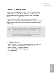
...our website for specific information about the model you for purchasing ASRock H410M-HDV / H410M-HVS motherboard, a reliable motherboard produced under ASRock's consistently stringent quality control. Because the motherboard specifications and the ...of the software and utilities. H410M-HDV H410M-HVS Chapter 1 Introduction Thank you are using. ASRock website http://www.asrock.com. 1.1 Package Contents • ASRock H410M-HDV / H410M-HVS Motherboard (Micro ATX Form Factor) • ASRock H410M-HDV / H410M-HVS Quick Installation Guide • ASRock H410M-HDV / H410M-HVS Support CD • ...
...our website for specific information about the model you for purchasing ASRock H410M-HDV / H410M-HVS motherboard, a reliable motherboard produced under ASRock's consistently stringent quality control. Because the motherboard specifications and the ...of the software and utilities. H410M-HDV H410M-HVS Chapter 1 Introduction Thank you are using. ASRock website http://www.asrock.com. 1.1 Package Contents • ASRock H410M-HDV / H410M-HVS Motherboard (Micro ATX Form Factor) • ASRock H410M-HDV / H410M-HVS Quick Installation Guide • ASRock H410M-HDV / H410M-HVS Support CD • ...

User Manual
Page 7
...; 1 x PCI Express 3.0 x1 Slot Graphics • Intel® UHD Graphics Built-in non- buffered memory * Please refer to Memory Support List on ASRock's website for more information. (http://www.asrock.com/) * CoreTM (i9/i7) support DDR4 up to 2933; CoreTM (i5/i3), Pentium® and Celeron® support DDR4 up to 2666...
...; 1 x PCI Express 3.0 x1 Slot Graphics • Intel® UHD Graphics Built-in non- buffered memory * Please refer to Memory Support List on ASRock's website for more information. (http://www.asrock.com/) * CoreTM (i9/i7) support DDR4 up to 2933; CoreTM (i5/i3), Pentium® and Celeron® support DDR4 up to 2666...

User Manual
Page 8
...Protection • PCIE x1 Gigabit LAN 10/100/1000 Mb/s • 1 x Realtek RTL8111H • Supports Wake-On-LAN 3 English Audio LAN H410M-HDV H410M-HVS • Graphics, Media & Compute: Microsoft DirectX 12, OpenGL 4.5, Intel® Built In Visuals, Intel® Quick Sync Video, Hybrid /... • Display & Content Security: Rec. 2020 (Wide Color Gamut), Microsoft PlayReady 3.0, Intel® SGX Content Protection, UHD/HDR Blu-ray Disc H410M-HDV: • Three graphics output options: D-Sub, DVI-D and HDMI * Supports up to 2 displays simultaneously • Supports HDMI 1.4 with max. ...
...Protection • PCIE x1 Gigabit LAN 10/100/1000 Mb/s • 1 x Realtek RTL8111H • Supports Wake-On-LAN 3 English Audio LAN H410M-HDV H410M-HVS • Graphics, Media & Compute: Microsoft DirectX 12, OpenGL 4.5, Intel® Built In Visuals, Intel® Quick Sync Video, Hybrid /... • Display & Content Security: Rec. 2020 (Wide Color Gamut), Microsoft PlayReady 3.0, Intel® SGX Content Protection, UHD/HDR Blu-ray Disc H410M-HDV: • Three graphics output options: D-Sub, DVI-D and HDMI * Supports up to 2 displays simultaneously • Supports HDMI 1.4 with max. ...

User Manual
Page 9
...; 1 x RJ-45 LAN Port with LED (ACT/LINK LED and SPEED LED) • HD Audio Jacks: Line in / Front Speaker / Microphone H410M-HDV: • 1 x D-Sub Port • 1 x DVI-D Port • 1 x HDMI Port H410M-HVS: • 1 x D-Sub Port • 1 x HDMI Port Storage • 4 x SATA3 6.0 Gb/s Connectors, support NCQ, AHCI and Hot Plug Connector •...
...; 1 x RJ-45 LAN Port with LED (ACT/LINK LED and SPEED LED) • HD Audio Jacks: Line in / Front Speaker / Microphone H410M-HDV: • 1 x D-Sub Port • 1 x DVI-D Port • 1 x HDMI Port H410M-HVS: • 1 x D-Sub Port • 1 x HDMI Port Storage • 4 x SATA3 6.0 Gb/s Connectors, support NCQ, AHCI and Hot Plug Connector •...

User Manual
Page 10
.... Overclocking may affect your system's stability, or even cause damage to the components and devices of your own risk and expense. H410M-HDV H410M-HVS BIOS Feature Hardware Monitor OS Certifications • AMI UEFI Legal BIOS with overclocking, including adjusting the setting in the BIOS,... CE • ErP/EuP ready (ErP/EuP ready power supply is required) * For detailed product information, please visit our website: http://www.asrock.com Please realize that there is a certain risk involved with multilingual GUI support • ACPI 6.0 Compliant wake up events • SMBIOS 2.7 Support...
.... Overclocking may affect your system's stability, or even cause damage to the components and devices of your own risk and expense. H410M-HDV H410M-HVS BIOS Feature Hardware Monitor OS Certifications • AMI UEFI Legal BIOS with overclocking, including adjusting the setting in the BIOS,... CE • ErP/EuP ready (ErP/EuP ready power supply is required) * For detailed product information, please visit our website: http://www.asrock.com Please realize that there is a certain risk involved with multilingual GUI support • ACPI 6.0 Compliant wake up events • SMBIOS 2.7 Support...

User Manual
Page 11
1.3 Motherboard Layout H410M-HDV: 6 English
1.3 Motherboard Layout H410M-HDV: 6 English

User Manual
Page 13
No. Description 1 ATX 12V Power Connector (ATX12V1) 2 Chassis/Water Pump Fan Connector (CHA_FAN1/WP) 3 CPU Fan Connector (CPU_FAN1) 4 2 x 288-pin DDR4 DIMM Slots (DDR4_A1, DDR4_B1) 5 ATX Power Connector (ATXPWR1) 6 USB 3.2 Gen1 Header (USB3_3_4) 7 Clear CMOS Jumper (CLRMOS1) 8 USB 2.0 Header (USB_5_6) 9 SATA3 Connector (SATA3_0) 10 SATA3 Connector (SATA3_1) 11 SATA3 Connector (SATA3_2) 12 SATA3 Connector (SATA3_3) 13 SPI TPM Header (SPI_TPM_J1) 14 Chassis Intrusion and Speaker Header (SPK_CI1) 15 System Panel Header (PANEL1) 16 Front Panel Audio Header (HD_AUDIO1) 8 English
No. Description 1 ATX 12V Power Connector (ATX12V1) 2 Chassis/Water Pump Fan Connector (CHA_FAN1/WP) 3 CPU Fan Connector (CPU_FAN1) 4 2 x 288-pin DDR4 DIMM Slots (DDR4_A1, DDR4_B1) 5 ATX Power Connector (ATXPWR1) 6 USB 3.2 Gen1 Header (USB3_3_4) 7 Clear CMOS Jumper (CLRMOS1) 8 USB 2.0 Header (USB_5_6) 9 SATA3 Connector (SATA3_0) 10 SATA3 Connector (SATA3_1) 11 SATA3 Connector (SATA3_2) 12 SATA3 Connector (SATA3_3) 13 SPI TPM Header (SPI_TPM_J1) 14 Chassis Intrusion and Speaker Header (SPK_CI1) 15 System Panel Header (PANEL1) 16 Front Panel Audio Header (HD_AUDIO1) 8 English

User Manual
Page 15
Please refer to the table below for the LAN port LED indications. ACT/LINK LED SPEED LED LAN Port Activity / Link LED Status Description Off Blinking On No Link Data Activity Link Speed LED Status Off Orange Green Description 10Mbps connection 100Mbps connection 1Gbps connection ** Function of the Audio Ports in 7.1-channel Configuration: Port Light Blue (Rear panel) Lime (Rear panel) Pink (Rear panel) Lime (Front panel) Function Rear Speaker Out Front Speaker Out Central /Subwoofer Speaker Out Side Speaker Out English 10 * There are two LEDs on each LAN port.
Please refer to the table below for the LAN port LED indications. ACT/LINK LED SPEED LED LAN Port Activity / Link LED Status Description Off Blinking On No Link Data Activity Link Speed LED Status Off Orange Green Description 10Mbps connection 100Mbps connection 1Gbps connection ** Function of the Audio Ports in 7.1-channel Configuration: Port Light Blue (Rear panel) Lime (Rear panel) Pink (Rear panel) Lime (Front panel) Function Rear Speaker Out Front Speaker Out Central /Subwoofer Speaker Out Side Speaker Out English 10 * There are two LEDs on each LAN port.
User Manual
Page 16
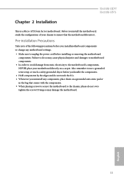
... chassis to the motherboard's components, NEVER place your motherboard directly on a grounded anti-static pad or in the bag that the motherboard fits into it. H410M-HDV H410M-HVS Chapter 2 Installation This is a Micro ATX form factor motherboard. Also remember to the chassis, please do so may damage the motherboard. 11 English...
... chassis to the motherboard's components, NEVER place your motherboard directly on a grounded anti-static pad or in the bag that the motherboard fits into it. H410M-HDV H410M-HVS Chapter 2 Installation This is a Micro ATX form factor motherboard. Also remember to the chassis, please do so may damage the motherboard. 11 English...

User Manual
Page 17
Unplug all power cables before installing the CPU. 1 A B 2 12 English Otherwise, the CPU will be seriously damaged. 2. Before you insert the 1200-Pin CPU into the socket if above situation is unclean, or if there are any bent pins in the socket. Do not force to insert the CPU into the socket, please check if the PnP cap is on the socket, if the CPU surface is found. 2.1 Installing the CPU 1.
Unplug all power cables before installing the CPU. 1 A B 2 12 English Otherwise, the CPU will be seriously damaged. 2. Before you insert the 1200-Pin CPU into the socket if above situation is unclean, or if there are any bent pins in the socket. Do not force to insert the CPU into the socket, please check if the PnP cap is on the socket, if the CPU surface is found. 2.1 Installing the CPU 1.

User Manual
Page 19
The cover must be placed if you wish to return the motherboard for after service. 14 English Please save and replace the cover if the processor is removed.
The cover must be placed if you wish to return the motherboard for after service. 14 English Please save and replace the cover if the processor is removed.

User Manual
Page 20
2.2 Installing the CPU Fan and Heatsink H410M-HDV H410M-HVS 1 2 CPU_FAN 15 English
2.2 Installing the CPU Fan and Heatsink H410M-HDV H410M-HVS 1 2 CPU_FAN 15 English

User Manual
Page 21
It will cause permanent damage to install identical (the same brand, speed, size and chip-type) DDR4 DIMM pairs. 2. otherwise, this motherboard and DIMM may be damaged. For dual channel configuration, you always need to the motherboard and the DIMM if you force the DIMM into a DDR4 slot; The DIMM only fits in one memory module installed. 3. 2.3 Installing Memory Modules (DIMM) This motherboard provides two 288-pin DDR4 (Double Data Rate 4) DIMM slots, and supports Dual Channel Memory Technology. 1. It is unable to install a DDR, DDR2 or DDR3 memory module into the slot at ...
It will cause permanent damage to install identical (the same brand, speed, size and chip-type) DDR4 DIMM pairs. 2. otherwise, this motherboard and DIMM may be damaged. For dual channel configuration, you always need to the motherboard and the DIMM if you force the DIMM into a DDR4 slot; The DIMM only fits in one memory module installed. 3. 2.3 Installing Memory Modules (DIMM) This motherboard provides two 288-pin DDR4 (Double Data Rate 4) DIMM slots, and supports Dual Channel Memory Technology. 1. It is unable to install a DDR, DDR2 or DDR3 memory module into the slot at ...

User Manual
Page 23
Before installing an expansion card, please make necessary hardware settings for the card before you start the installation. PCIE2 (PCIe 3.0 x16 slot) is used for PCI Express x16 lane width graphics cards. 18 English 2.4 Expansion Slots (PCI Express Slots) There are 2 PCI Express slots on the motherboard. PCIe slots: PCIE1 (PCIe 3.0 x1 slot) is unplugged. Please read the documentation of the expansion card and make sure that the power supply is switched off or the power cord is used for PCI Express x1 lane width cards.
Before installing an expansion card, please make necessary hardware settings for the card before you start the installation. PCIE2 (PCIe 3.0 x16 slot) is used for PCI Express x16 lane width graphics cards. 18 English 2.4 Expansion Slots (PCI Express Slots) There are 2 PCI Express slots on the motherboard. PCIe slots: PCIE1 (PCIe 3.0 x1 slot) is unplugged. Please read the documentation of the expansion card and make sure that the power supply is switched off or the power cord is used for PCI Express x1 lane width cards.

User Manual
Page 24
... of previous chassis intrusion status. Please adjust the BIOS option "Clear Status" to remove the jumper cap after clearing the CMOS. The data in CMOS. H410M-HDV H410M-HVS 2.5 Jumpers Setup The illustration shows how jumpers are setup. If you need to short the pins on the pins, the jumper is "Short". To...
... of previous chassis intrusion status. Please adjust the BIOS option "Clear Status" to remove the jumper cap after clearing the CMOS. The data in CMOS. H410M-HDV H410M-HVS 2.5 Jumpers Setup The illustration shows how jumpers are setup. If you need to short the pins on the pins, the jumper is "Short". To...

User Manual
Page 25
Note the positive and negative pins before connecting the cables. The LED is off when the system is operating. The LED is on when the system is in S1/S3 sleep state. The front panel design may configure the way to turn off (S5). English System Panel Header (9-pin PANEL1) (see p.6, 7, No. 14) 20 SPEAKER DUMMY DUMMY +5V 1 SIGNAL GND DUMMY Please connect the chassis intrusion and the chassis speaker to the motherboard. The LED is on when the hard drive is in S4 sleep state or powered off your chassis front panel module to this header, make sure the wire assignments and...
Note the positive and negative pins before connecting the cables. The LED is off when the system is operating. The LED is on when the system is in S1/S3 sleep state. The front panel design may configure the way to turn off (S5). English System Panel Header (9-pin PANEL1) (see p.6, 7, No. 14) 20 SPEAKER DUMMY DUMMY +5V 1 SIGNAL GND DUMMY Please connect the chassis intrusion and the chassis speaker to the motherboard. The LED is on when the hard drive is in S4 sleep state or powered off your chassis front panel module to this header, make sure the wire assignments and...
