
User Manual
Page 4
... Contents 1 1.2 Specifications 2 1.3 Motherboard Layout 6 1.4 I/O Panel 9 Chapter 2 Installation 11 2.1 Installing the CPU 12 2.2 Installing the CPU Fan and Heatsink 15 2.3 Installing Memory Modules (DIMM) 16 2.4 Expansion Slots (PCI Express Slots) 18 2.5 Jumpers Setup 19 2.6 Onboard Headers and Connectors 20 Chapter 3 Software and Utilities Operation 24 3.1 Installing Drivers 24 3.2 ASRock Motherboard Utility (A-Tuning) 25 3.2.1 Installing ASRock Motherboard Utility (A-Tuning) 25 3.2.2 Using ASRock Motherboard Utility (A-Tuning) 25 3.3 ASRock Live Update & APP...
... Contents 1 1.2 Specifications 2 1.3 Motherboard Layout 6 1.4 I/O Panel 9 Chapter 2 Installation 11 2.1 Installing the CPU 12 2.2 Installing the CPU Fan and Heatsink 15 2.3 Installing Memory Modules (DIMM) 16 2.4 Expansion Slots (PCI Express Slots) 18 2.5 Jumpers Setup 19 2.6 Onboard Headers and Connectors 20 Chapter 3 Software and Utilities Operation 24 3.1 Installing Drivers 24 3.2 ASRock Motherboard Utility (A-Tuning) 25 3.2.1 Installing ASRock Motherboard Utility (A-Tuning) 25 3.2.2 Using ASRock Motherboard Utility (A-Tuning) 25 3.3 ASRock Live Update & APP...
User Manual
Page 6
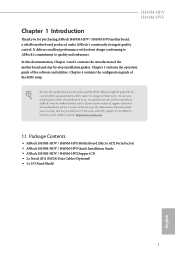
... VGA cards and CPU support list on ASRock's website without notice. H410M-HDV H410M-HVS Chapter 1 Introduction Thank you for specific information about the model you require technical support related to quality and endurance. In case any modifications of the BIOS setup. ASRock website http://www.asrock.com. 1.1 Package Contents • ASRock H410M-HDV / H410M-HVS Motherboard (Micro ATX Form Factor) • ASRock H410M-HDV / H410M-HVS Quick Installation Guide • ASRock H410M-HDV / H410M-HVS Support CD • 2 x Serial ATA (SATA) Data Cables (Optional) • 1 x I/O Panel...
... VGA cards and CPU support list on ASRock's website without notice. H410M-HDV H410M-HVS Chapter 1 Introduction Thank you for specific information about the model you require technical support related to quality and endurance. In case any modifications of the BIOS setup. ASRock website http://www.asrock.com. 1.1 Package Contents • ASRock H410M-HDV / H410M-HVS Motherboard (Micro ATX Form Factor) • ASRock H410M-HDV / H410M-HVS Quick Installation Guide • ASRock H410M-HDV / H410M-HVS Support CD • 2 x Serial ATA (SATA) Data Cables (Optional) • 1 x I/O Panel...

User Manual
Page 8
...), xvYCC and HBR (High Bit Rate Audio) with HDMI 1.4 Port (Compliant HDMI monitor is required) • Supports HDCP 2.3 with HDMI 1.4 Port • Supports 4K Ultra HD (UHD) playback with HDMI 1.4 Port • 7.1 CH HD Audio (Realtek ALC887 Audio Codec) • Supports Surge Protection • PCIE x1 Gigabit LAN 10/100/1000 Mb/s • 1 x Realtek RTL8111H • Supports Wake-On-LAN 3 English resolution up to 2 displays simultaneously • Supports HDMI 1.4 with max. Audio LAN H410M-HDV H410M-HVS • Graphics, Media & Compute...
...), xvYCC and HBR (High Bit Rate Audio) with HDMI 1.4 Port (Compliant HDMI monitor is required) • Supports HDCP 2.3 with HDMI 1.4 Port • Supports 4K Ultra HD (UHD) playback with HDMI 1.4 Port • 7.1 CH HD Audio (Realtek ALC887 Audio Codec) • Supports Surge Protection • PCIE x1 Gigabit LAN 10/100/1000 Mb/s • 1 x Realtek RTL8111H • Supports Wake-On-LAN 3 English resolution up to 2 displays simultaneously • Supports HDMI 1.4 with max. Audio LAN H410M-HDV H410M-HVS • Graphics, Media & Compute...

User Manual
Page 9
...RJ-45 LAN Port with LED (ACT/LINK LED and SPEED LED) • HD Audio Jacks: Line in / Front Speaker / Microphone H410M-HDV: • 1 x D-Sub Port • 1 x DVI-D Port • 1 x HDMI Port H410M-HVS: • 1 x D-Sub Port • 1 x HDMI Port Storage • 4 x SATA3 6.0 Gb/s Connectors, support NCQ, AHCI and Hot Plug Connector • 1 x SPI TPM Header • 1 x Chassis Intrusion and Speaker Header • 1 x CPU Fan Connector (4-pin) * The CPU Fan Connector supports the CPU fan of maximum 1A (12W) fan power. • 1 x Chassis/Water Pump Fan Connector (4-pin) (Smart Fan Speed...
...RJ-45 LAN Port with LED (ACT/LINK LED and SPEED LED) • HD Audio Jacks: Line in / Front Speaker / Microphone H410M-HDV: • 1 x D-Sub Port • 1 x DVI-D Port • 1 x HDMI Port H410M-HVS: • 1 x D-Sub Port • 1 x HDMI Port Storage • 4 x SATA3 6.0 Gb/s Connectors, support NCQ, AHCI and Hot Plug Connector • 1 x SPI TPM Header • 1 x Chassis Intrusion and Speaker Header • 1 x CPU Fan Connector (4-pin) * The CPU Fan Connector supports the CPU fan of maximum 1A (12W) fan power. • 1 x Chassis/Water Pump Fan Connector (4-pin) (Smart Fan Speed...

User Manual
Page 10
... power supply is required) * For detailed product information, please visit our website: http://www.asrock.com Please realize that there is a certain risk involved with multilingual GUI support • ACPI 6.0 Compliant wake up events • SMBIOS 2.7 Support • CPU Core/Cache, GT, DRAM, PCH +1.0V, VCCST Voltage Multi-adjustment • Temperature Sensing: CPU, Chassis/Water Pump Fans • Fan Tachometer: CPU, Chassis/Water Pump Fans • Quiet Fan (Auto adjust chassis fan speed by overclocking. Overclocking...
... power supply is required) * For detailed product information, please visit our website: http://www.asrock.com Please realize that there is a certain risk involved with multilingual GUI support • ACPI 6.0 Compliant wake up events • SMBIOS 2.7 Support • CPU Core/Cache, GT, DRAM, PCH +1.0V, VCCST Voltage Multi-adjustment • Temperature Sensing: CPU, Chassis/Water Pump Fans • Fan Tachometer: CPU, Chassis/Water Pump Fans • Quiet Fan (Auto adjust chassis fan speed by overclocking. Overclocking...

User Manual
Page 13
Description 1 ATX 12V Power Connector (ATX12V1) 2 Chassis/Water Pump Fan Connector (CHA_FAN1/WP) 3 CPU Fan Connector (CPU_FAN1) 4 2 x 288-pin DDR4 DIMM Slots (DDR4_A1, DDR4_B1) 5 ATX Power Connector (ATXPWR1) 6 USB 3.2 Gen1 Header (USB3_3_4) 7 Clear CMOS Jumper (CLRMOS1) 8 USB 2.0 Header (USB_5_6) 9 SATA3 Connector (SATA3_0) 10 SATA3 Connector (SATA3_1) 11 SATA3 Connector (SATA3_2) 12 SATA3 Connector (SATA3_3) 13 SPI TPM Header (SPI_TPM_J1) 14 Chassis Intrusion and Speaker Header (SPK_CI1) 15 System Panel Header (PANEL1) 16 Front Panel Audio Header (HD_AUDIO1) 8 English No.
Description 1 ATX 12V Power Connector (ATX12V1) 2 Chassis/Water Pump Fan Connector (CHA_FAN1/WP) 3 CPU Fan Connector (CPU_FAN1) 4 2 x 288-pin DDR4 DIMM Slots (DDR4_A1, DDR4_B1) 5 ATX Power Connector (ATXPWR1) 6 USB 3.2 Gen1 Header (USB3_3_4) 7 Clear CMOS Jumper (CLRMOS1) 8 USB 2.0 Header (USB_5_6) 9 SATA3 Connector (SATA3_0) 10 SATA3 Connector (SATA3_1) 11 SATA3 Connector (SATA3_2) 12 SATA3 Connector (SATA3_3) 13 SPI TPM Header (SPI_TPM_J1) 14 Chassis Intrusion and Speaker Header (SPK_CI1) 15 System Panel Header (PANEL1) 16 Front Panel Audio Header (HD_AUDIO1) 8 English No.

User Manual
Page 23
PCIe slots: PCIE1 (PCIe 3.0 x1 slot) is unplugged. Before installing an expansion card, please make necessary hardware settings for PCI Express x1 lane width cards. Please read the documentation of the expansion card and make sure that the power supply is switched off or the power cord is used for PCI Express x16 lane width graphics cards. 18 English PCIE2 (PCIe 3.0 x16 slot) is used for the card before you start the installation. 2.4 Expansion Slots (PCI Express Slots) There are 2 PCI Express slots on the motherboard.
PCIe slots: PCIE1 (PCIe 3.0 x1 slot) is unplugged. Before installing an expansion card, please make necessary hardware settings for PCI Express x1 lane width cards. Please read the documentation of the expansion card and make sure that the power supply is switched off or the power cord is used for PCI Express x16 lane width graphics cards. 18 English PCIE2 (PCIe 3.0 x16 slot) is used for the card before you start the installation. 2.4 Expansion Slots (PCI Express Slots) There are 2 PCI Express slots on the motherboard.

User Manual
Page 24
... need to clear the data in CMOS includes system setup information such as system password, date, time, and system setup parameters. When the jumper cap is placed on CLRMOS1 for 3 seconds. Please remember to short the pins on the pins, the jumper is "Open". H410M-HDV H410M-HVS 2.5 Jumpers Setup The illustration shows how jumpers are setup. Please adjust the BIOS option "Clear Status" to clear the record of previous chassis intrusion...
... need to clear the data in CMOS includes system setup information such as system password, date, time, and system setup parameters. When the jumper cap is placed on CLRMOS1 for 3 seconds. Please remember to short the pins on the pins, the jumper is "Open". H410M-HDV H410M-HVS 2.5 Jumpers Setup The illustration shows how jumpers are setup. Please adjust the BIOS option "Clear Status" to clear the record of previous chassis intrusion...

User Manual
Page 25
... hard drive activity LED on the chassis front panel. When connecting your system using the power button. HDLED (Hard Drive Activity LED): Connect to the power status indicator on the chassis front panel. A front panel module mainly consists of power button, reset button, power LED, hard drive activity LED, speaker and etc. The front panel design may configure the way to turn off (S5). Placing jumper caps over these headers and connectors. RESET (Reset Button): Connect to the motherboard. The LED is on the chassis to this header. System Panel Header (9-pin PANEL1...
... hard drive activity LED on the chassis front panel. When connecting your system using the power button. HDLED (Hard Drive Activity LED): Connect to the power status indicator on the chassis front panel. A front panel module mainly consists of power button, reset button, power LED, hard drive activity LED, speaker and etc. The front panel design may configure the way to turn off (S5). Placing jumper caps over these headers and connectors. RESET (Reset Button): Connect to the motherboard. The LED is on the chassis to this header. System Panel Header (9-pin PANEL1...
User Manual
Page 26
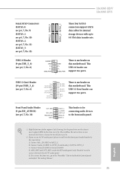
... motherboard. If you use an AC'97 audio panel, please install it to Ground (GND). To activate the front mic, go to 6.0 Gb/s data transfer rate. H410M-HDV H410M-HVS Serial ATA3 Connectors (SATA3_0: see p.6, 7, No. 9) (SATA3_1: see p.6, 7, No. 10) (SATA3_2: see p.6, 7, No. 11) (SATA3_3: see p.6, 7, No. 12) USB 2.0 Header (9-pin USB_5_6) (see p.6, 7, No. 8) SATA3_2 SATA3_0 SATA3_3 SATA3_1 These four SATA3 connectors support SATA data cables for internal storage devices...
... motherboard. If you use an AC'97 audio panel, please install it to Ground (GND). To activate the front mic, go to 6.0 Gb/s data transfer rate. H410M-HDV H410M-HVS Serial ATA3 Connectors (SATA3_0: see p.6, 7, No. 9) (SATA3_1: see p.6, 7, No. 10) (SATA3_2: see p.6, 7, No. 11) (SATA3_3: see p.6, 7, No. 12) USB 2.0 Header (9-pin USB_5_6) (see p.6, 7, No. 8) SATA3_2 SATA3_0 SATA3_3 SATA3_1 These four SATA3 connectors support SATA data cables for internal storage devices...

User Manual
Page 27
... motherboard provides a 4-Pin CPU fan (Quiet Fan) connector. To use a 4-pin ATX power supply, please plug it along Pin 1 and Pin 5. *Warning: Please make sure that the power cable connected is for the CPU and not the graphics card. ATX Power Connector (24-pin ATXPWR1) (see p.6, 7, No. 2) a 3-Pin chassis water cooler fan, please connect it to connect (see p.6, 7, No. 5) 12 24 1 13 This motherboard provides a 24-pin ATX power connector. If you plan to connect a 3-Pin CPU fan, please connect it to this connector. Do not plug the PCIe power cable to Pin...
... motherboard provides a 4-Pin CPU fan (Quiet Fan) connector. To use a 4-pin ATX power supply, please plug it along Pin 1 and Pin 5. *Warning: Please make sure that the power cable connected is for the CPU and not the graphics card. ATX Power Connector (24-pin ATXPWR1) (see p.6, 7, No. 2) a 3-Pin chassis water cooler fan, please connect it to connect (see p.6, 7, No. 5) 12 24 1 13 This motherboard provides a 24-pin ATX power connector. If you plan to connect a 3-Pin CPU fan, please connect it to this connector. Do not plug the PCIe power cable to Pin...
User Manual
Page 29
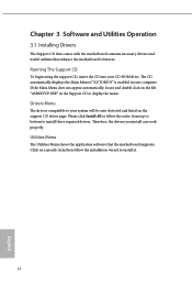
... English Please click Install All or follow the installation wizard to display the menu. Utilities Menu The Utilities Menu shows the application software that enhance the motherboard's features. Running The Support CD To begin using the support CD, insert the CD into your CD-ROM drive. Therefore, the drivers you install can work properly. Chapter 3 Software and Utilities Operation 3.1 Installing Drivers The Support CD that comes with the motherboard contains necessary drivers and useful utilities that the motherboard supports.
... English Please click Install All or follow the installation wizard to display the menu. Utilities Menu The Utilities Menu shows the application software that enhance the motherboard's features. Running The Support CD To begin using the support CD, insert the CD into your CD-ROM drive. Therefore, the drivers you install can work properly. Chapter 3 Software and Utilities Operation 3.1 Installing Drivers The Support CD that comes with the motherboard contains necessary drivers and useful utilities that the motherboard supports.

User Manual
Page 46
... requests the highest performance state. DRAM Frequency If [Auto] is selected, the motherboard will expose the CPPC v2 interface to run at the same frequency. H410M-HDV H410M-HVS Boot Performance Mode Select the performance state that implment the Intel Thermal Velocity Boost (TVB) feature. Intel SpeedStep Technology Intel SpeedStep technology allows processors to overclock the memory and perform beyond standard specifications. Intel Speed Shift Technology Enable/Disable Intel Speed Shift Technology support.
... requests the highest performance state. DRAM Frequency If [Auto] is selected, the motherboard will expose the CPPC v2 interface to run at the same frequency. H410M-HDV H410M-HVS Boot Performance Mode Select the performance state that implment the Intel Thermal Velocity Boost (TVB) feature. Intel SpeedStep Technology Intel SpeedStep technology allows processors to overclock the memory and perform beyond standard specifications. Intel Speed Shift Technology Enable/Disable Intel Speed Shift Technology support.

User Manual
Page 56
... if the system supports 64 bit PCI decoding). PCIE1 Link Speed Select the link speed for overclocking. DMI Link Speed Configure DMI Slot Link Speed. SR-IOV Support If system has SR-IOV capable PCIe Devices, this option Enables or Disables Single Root IO Virtualization Support. Auto mode is optimizing for PCIE1. 51 English 4.6.2 Chipset Configuration H410M-HDV H410M-HVS Primary Graphics Adapter Select a primary VGA. VT-d Intel® Virtualization Technology for Directed I/O helps your virtual machine monitor better utilize hardware by...
... if the system supports 64 bit PCI decoding). PCIE1 Link Speed Select the link speed for overclocking. DMI Link Speed Configure DMI Slot Link Speed. SR-IOV Support If system has SR-IOV capable PCIe Devices, this option Enables or Disables Single Root IO Virtualization Support. Auto mode is optimizing for PCIE1. 51 English 4.6.2 Chipset Configuration H410M-HDV H410M-HVS Primary Graphics Adapter Select a primary VGA. VT-d Intel® Virtualization Technology for Directed I/O helps your virtual machine monitor better utilize hardware by...

User Manual
Page 57
... graphics processor when the system boots up. Set to Auto to disable the integrated graphics when an external graphics card is installed. PCI Express Native Control Select Enable for all PCH DMI devices. PCH DMI ASPM Support This option enables/disables the ASPM support for enhanced PCI Express power saving in OS. Front Panel Enable/disable front panel HD audio. Onboard HDMI HD Audio Enable audio for all PCH PCIE devices. PCH PCIE ASPM Support This option enables/disables the ASPM support for the onboard digital outputs. 52 English IGPU Multi-Monitor Select disable...
... graphics processor when the system boots up. Set to Auto to disable the integrated graphics when an external graphics card is installed. PCI Express Native Control Select Enable for all PCH DMI devices. PCH DMI ASPM Support This option enables/disables the ASPM support for enhanced PCI Express power saving in OS. Front Panel Enable/disable front panel HD audio. Onboard HDMI HD Audio Enable audio for all PCH PCIE devices. PCH PCIE ASPM Support This option enables/disables the ASPM support for the onboard digital outputs. 52 English IGPU Multi-Monitor Select disable...
User Manual
Page 62
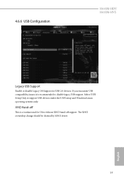
If you encounter USB compatibility issues it is a workaround for USB 2.0 devices. The XHCI ownership change should be claimed by XHCI driver. 57 English 4.6.6 USB Configuration H410M-HDV H410M-HVS Legacy USB Support Enable or disable Legacy OS Support for OSes without XHCI hand-off This is recommended to support USB devices under the UEFI setup and Windows/Linux operating systems only. Select UEFI Setup Only to disable legacy USB support. XHCI Hand-off support.
If you encounter USB compatibility issues it is a workaround for USB 2.0 devices. The XHCI ownership change should be claimed by XHCI driver. 57 English 4.6.6 USB Configuration H410M-HDV H410M-HVS Legacy USB Support Enable or disable Legacy OS Support for OSes without XHCI hand-off This is recommended to support USB devices under the UEFI setup and Windows/Linux operating systems only. Select UEFI Setup Only to disable legacy USB support. XHCI Hand-off support.
User Manual
Page 64
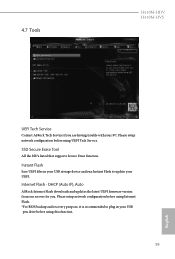
... UEFI files in your USB pen drive before using UEFI Tech Service. DHCP (Auto IP), Auto ASRock Internet Flash downloads and updates the latest UEFI firmware version from our servers for you are having trouble with your UEFI. Internet Flash - Please setup network configuration before using this function. 59 English Please setup network configuration before using Internet Flash. *For BIOS backup and recovery purpose, it is recommended to plug in your USB storage device and run Instant Flash to update your PC. 4.7 Tools H410M-HDV H410M-HVS UEFI Tech Service Contact ASRock...
... UEFI files in your USB pen drive before using UEFI Tech Service. DHCP (Auto IP), Auto ASRock Internet Flash downloads and updates the latest UEFI firmware version from our servers for you are having trouble with your UEFI. Internet Flash - Please setup network configuration before using this function. 59 English Please setup network configuration before using Internet Flash. *For BIOS backup and recovery purpose, it is recommended to plug in your USB storage device and run Instant Flash to update your PC. 4.7 Tools H410M-HDV H410M-HVS UEFI Tech Service Contact ASRock...

User Manual
Page 65
UEFI Download Server Select a server to configure internet connection settings for Internet Flash. Internet Setting Enable or disable sound effects in the setup utility. Network Configuration Use this to download the UEFI firmware. 60 English
UEFI Download Server Select a server to configure internet connection settings for Internet Flash. Internet Setting Enable or disable sound effects in the setup utility. Network Configuration Use this to download the UEFI firmware. 60 English

User Manual
Page 67
Chassis Fan 1 Step Down Set the value of Chassis Fan 1 Step Up. Chassis Fan 1 Temp Source Select a fan temperature source for CHA_FAN1. Chassis Fan 1 Setting Select a fan mode for each temperature. Chassis Fan 1 Step Up Set the value of Chassis Fan 1 Step Down. Chassis Fan 1 Control Mode Select PWM mode or DC mode for Chassis Fan 1. Case Open Feature Enable or disable Case Open Feature to set 5 CPU temperatures and assign a respective fan speed for CHA_FAN1, or choose Customize to detect whether the chassis cover has been removed. 62 English
Chassis Fan 1 Step Down Set the value of Chassis Fan 1 Step Up. Chassis Fan 1 Temp Source Select a fan temperature source for CHA_FAN1. Chassis Fan 1 Setting Select a fan mode for each temperature. Chassis Fan 1 Step Up Set the value of Chassis Fan 1 Step Down. Chassis Fan 1 Control Mode Select PWM mode or DC mode for Chassis Fan 1. Case Open Feature Enable or disable Case Open Feature to set 5 CPU temperatures and assign a respective fan speed for CHA_FAN1, or choose Customize to detect whether the chassis cover has been removed. 62 English

User Manual
Page 68
... Technology Enable/disable Intel PTT in the UEFI Setup Utility. You may set or change the settings in the UEFI Setup Utility. Leave it blank and press enter to change the supervisor/user password for Secure Boot. Secure Boot Use this item to remove the password. Supervisor Password Set or change the settings in ME. Only the administrator has authority to remove the password. Leave it blank and press enter to enable or disable support for the system. Disable this option to change the password...
... Technology Enable/disable Intel PTT in the UEFI Setup Utility. You may set or change the settings in the UEFI Setup Utility. Leave it blank and press enter to change the supervisor/user password for Secure Boot. Secure Boot Use this item to remove the password. Supervisor Password Set or change the settings in ME. Only the administrator has authority to remove the password. Leave it blank and press enter to enable or disable support for the system. Disable this option to change the password...


