Quick Installation Guide
Page 3
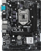
... PS2 Keyboard Motherboard Layout 1 ATX12V1 H310CM-HDVP/DASH 2 3 RoHS CPU_FAN1 COM1 DVI1 4 ATXPWR1 DDR4_A1 (64 bit, 288-pin module) DDR4_B1 (64 bit, 288-pin module) VGA1 HDMI1 USB 2.0 USB 2.0 T: USB0 T: USB2 B: USB1 B: USB3 USB 3.1 Gen1 Top: T: USB0 B: USB1 RJ-45 Top: LINE IN Center: FRONT Bottom: MIC IN HD_AUDIO1 CHA_FAN1/WP CT4 CT3 CT2 CT1 H310CM-HDVP/DASH 19 1 18 PCIE1 M2_1 USB3_2_3 5 1 PCIE2 CMOS Battery Intel H310...
... PS2 Keyboard Motherboard Layout 1 ATX12V1 H310CM-HDVP/DASH 2 3 RoHS CPU_FAN1 COM1 DVI1 4 ATXPWR1 DDR4_A1 (64 bit, 288-pin module) DDR4_B1 (64 bit, 288-pin module) VGA1 HDMI1 USB 2.0 USB 2.0 T: USB0 T: USB2 B: USB1 B: USB3 USB 3.1 Gen1 Top: T: USB0 B: USB1 RJ-45 Top: LINE IN Center: FRONT Bottom: MIC IN HD_AUDIO1 CHA_FAN1/WP CT4 CT3 CT2 CT1 H310CM-HDVP/DASH 19 1 18 PCIE1 M2_1 USB3_2_3 5 1 PCIE2 CMOS Battery Intel H310...
Quick Installation Guide
Page 4
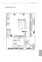
...) 2 CPU Fan Connector (CPU_FAN1) 3 2 x 288-pin DDR4 DIMM Slots (DDR4_A1, DDR4_B1) 4 ATX Power Connector (ATXPWR1) 5 USB 2.0 Header (USB_8_9) (shared with USB3_2_3) 6 SATA3 Connector (SATA3_3) 7 SATA3 Connector (SATA3_2) 8 SATA3 Connector (SATA3_1) 9 SATA3 Connector (SATA3_0) 10 Clear CMOS Jumper (CLRMOS1) 11 System Panel Header (PANEL1) 12 Chassis Fan Connector (CHA_FAN2) 13 USB 2.0 Header (USB_4_5) 14 Chassis Intrusion and Speaker Header (SPK_CI1) 15 Print Port Header (LPT1) 16 TPM Header (TPMS1) 17 COM Port Header (COM2) 18 Chassis/Water Pump Fan Connector (CHA_FAN1/WP) 19 Front Panel Audio...
...) 2 CPU Fan Connector (CPU_FAN1) 3 2 x 288-pin DDR4 DIMM Slots (DDR4_A1, DDR4_B1) 4 ATX Power Connector (ATXPWR1) 5 USB 2.0 Header (USB_8_9) (shared with USB3_2_3) 6 SATA3 Connector (SATA3_3) 7 SATA3 Connector (SATA3_2) 8 SATA3 Connector (SATA3_1) 9 SATA3 Connector (SATA3_0) 10 Clear CMOS Jumper (CLRMOS1) 11 System Panel Header (PANEL1) 12 Chassis Fan Connector (CHA_FAN2) 13 USB 2.0 Header (USB_4_5) 14 Chassis Intrusion and Speaker Header (SPK_CI1) 15 Print Port Header (LPT1) 16 TPM Header (TPMS1) 17 COM Port Header (COM2) 18 Chassis/Water Pump Fan Connector (CHA_FAN1/WP) 19 Front Panel Audio...
User Manual
Page 4
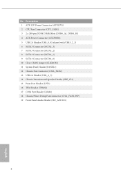
... 1 1.2 Specifications 2 1.3 Motherboard Layout 6 1.4 I/O Panel 8 Chapter 2 Installation 10 2.1 Installing the CPU 11 2.2 Installing the CPU Fan and Heatsink 14 2.3 Installing Memory Modules (DIMM) 15 2.4 Expansion Slots (PCI and PCI Express Slots) 17 2.5 Jumpers Setup 18 2.6 Onboard Headers and Connectors 19 2.7 M.2_SSD (NGFF) Module Installation Guide 23 Chapter 3 Software and Utilities Operation 27 3.1 Installing Drivers 27 3.2 A-Tuning 28 3.3 ASRock Live Update & APP Shop 31 3.3.1 UI Overview 31 3.3.2 Apps 32 3.3.3 BIOS & Drivers 35 3.3.4 Setting 36
... 1 1.2 Specifications 2 1.3 Motherboard Layout 6 1.4 I/O Panel 8 Chapter 2 Installation 10 2.1 Installing the CPU 11 2.2 Installing the CPU Fan and Heatsink 14 2.3 Installing Memory Modules (DIMM) 15 2.4 Expansion Slots (PCI and PCI Express Slots) 17 2.5 Jumpers Setup 18 2.6 Onboard Headers and Connectors 19 2.7 M.2_SSD (NGFF) Module Installation Guide 23 Chapter 3 Software and Utilities Operation 27 3.1 Installing Drivers 27 3.2 A-Tuning 28 3.3 ASRock Live Update & APP Shop 31 3.3.1 UI Overview 31 3.3.2 Apps 32 3.3.3 BIOS & Drivers 35 3.3.4 Setting 36

User Manual
Page 6
... of the BIOS setup. ASRock website http://www.asrock.com. 1.1 Package Contents • ASRock H310CM-HDVP/DASH Motherboard (Micro ATX Form Factor) • ASRock H310CM-HDVP/DASH Quick Installation Guide • ASRock H310CM-HDVP/DASH Support CD • 1 x I/O Panel Shield • 2 x Serial ATA (SATA) Data Cables (Optional) • 1 x Screw for purchasing ASRock H310CM-HDVP/DASH motherboard, a reliable motherboard produced under ASRock's consistently stringent quality control. If you are using. You may find the latest VGA cards and CPU support list on ASRock's website without...
... of the BIOS setup. ASRock website http://www.asrock.com. 1.1 Package Contents • ASRock H310CM-HDVP/DASH Motherboard (Micro ATX Form Factor) • ASRock H310CM-HDVP/DASH Quick Installation Guide • ASRock H310CM-HDVP/DASH Support CD • 1 x I/O Panel Shield • 2 x Serial ATA (SATA) Data Cables (Optional) • 1 x Screw for purchasing ASRock H310CM-HDVP/DASH motherboard, a reliable motherboard produced under ASRock's consistently stringent quality control. If you are using. You may find the latest VGA cards and CPU support list on ASRock's website without...
User Manual
Page 8
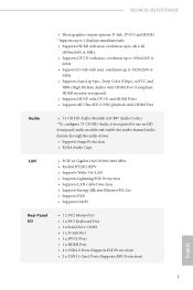
...; Supports HDMI with max. H310CM-HDVP/DASH • Three graphics output options: D-Sub, DVI-D and HDMI * Supports up to 1920x1200 @ 60Hz • Supports Auto Lip Sync, Deep Color (12bpc), xvYCC and HBR (High Bit Rate Audio) with HDMI Port (Compliant HDMI monitor is required) • Supports HDCP with DVI-D and HDMI Ports • Supports 4K Ultra HD (UHD) playback with HDMI Port Audio • 7.1 CH HD Audio (Realtek ALC887 Audio Codec) * To configure 7.1 CH HD Audio, it is required to use...
...; Supports HDMI with max. H310CM-HDVP/DASH • Three graphics output options: D-Sub, DVI-D and HDMI * Supports up to 1920x1200 @ 60Hz • Supports Auto Lip Sync, Deep Color (12bpc), xvYCC and HBR (High Bit Rate Audio) with HDMI Port (Compliant HDMI monitor is required) • Supports HDCP with DVI-D and HDMI Ports • Supports 4K Ultra HD (UHD) playback with HDMI Port Audio • 7.1 CH HD Audio (Realtek ALC887 Audio Codec) * To configure 7.1 CH HD Audio, it is required to use...
User Manual
Page 9
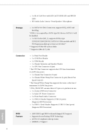
...be disabled. • 1 x M.2 Socket (M2_1), supports M Key type 2230/2242/2260/2280 M.2 SATA3 6.0 Gb/s module and M.2 PCI Express module up to Gen2 x2 (10 Gb/s)** ** Supports NVMe SSD as boot disks ** Supports ASRock U.2 Kit Connector • 1 x Print Port Header • 1 x COM Port Header • 1 x TPM Header • 1 x Chassis Intrusion and Speaker Header • 1 x CPU Fan Connector (4-pin) * The CPU Fan Connector supports the CPU fan of maximum 1A (12W) fan power. • 1 x Chassis Fan Connector (4-pin) • 1 x Chassis/Water Pump Fan Connector (4-pin) (Smart Fan Speed Control...
...be disabled. • 1 x M.2 Socket (M2_1), supports M Key type 2230/2242/2260/2280 M.2 SATA3 6.0 Gb/s module and M.2 PCI Express module up to Gen2 x2 (10 Gb/s)** ** Supports NVMe SSD as boot disks ** Supports ASRock U.2 Kit Connector • 1 x Print Port Header • 1 x COM Port Header • 1 x TPM Header • 1 x Chassis Intrusion and Speaker Header • 1 x CPU Fan Connector (4-pin) * The CPU Fan Connector supports the CPU fan of maximum 1A (12W) fan power. • 1 x Chassis Fan Connector (4-pin) • 1 x Chassis/Water Pump Fan Connector (4-pin) (Smart Fan Speed Control...

User Manual
Page 10
... the setting in the BIOS, applying Untied Overclocking Technology, or using third-party overclocking tools. Overclocking may affect your system's stability, or even cause damage to the components and devices of your own risk and expense. English 5 H310CM-HDVP/DASH Hardware Monitor OS Certifications • CPU, GT_CPU, DRAM, PCH 1.05V Voltage Multiadjustment • Temperature Sensing: CPU, Chassis, Chassis/Water Pump Fans • Fan Tachometer: CPU, Chassis, Chassis/Water Pump Fans • Quiet Fan (Auto adjust chassis fan speed by overclocking. It...
... the setting in the BIOS, applying Untied Overclocking Technology, or using third-party overclocking tools. Overclocking may affect your system's stability, or even cause damage to the components and devices of your own risk and expense. English 5 H310CM-HDVP/DASH Hardware Monitor OS Certifications • CPU, GT_CPU, DRAM, PCH 1.05V Voltage Multiadjustment • Temperature Sensing: CPU, Chassis, Chassis/Water Pump Fans • Fan Tachometer: CPU, Chassis, Chassis/Water Pump Fans • Quiet Fan (Auto adjust chassis fan speed by overclocking. It...
User Manual
Page 12
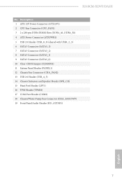
H310CM-HDVP/DASH No. Description 1 ATX 12V Power Connector (ATX12V1) 2 CPU Fan Connector (CPU_FAN1) 3 2 x 288-pin DDR4 DIMM Slots (DDR4_A1, DDR4_B1) 4 ATX Power Connector (ATXPWR1) 5 USB 2.0 Header (USB_8_9) (shared with USB3_2_3) 6 SATA3 Connector (SATA3_3) 7 SATA3 Connector (SATA3_2) 8 SATA3 Connector (SATA3_1) 9 SATA3 Connector (SATA3_0) 10 Clear CMOS Jumper (CLRMOS1) 11 System Panel Header (PANEL1) 12 Chassis Fan Connector (CHA_FAN2) 13 USB 2.0 Header (USB_4_5) 14 Chassis Intrusion and Speaker Header (SPK_CI1) 15 Print Port Header (LPT1) 16 TPM Header (TPMS1) 17 COM Port Header (COM2) 18 ...
H310CM-HDVP/DASH No. Description 1 ATX 12V Power Connector (ATX12V1) 2 CPU Fan Connector (CPU_FAN1) 3 2 x 288-pin DDR4 DIMM Slots (DDR4_A1, DDR4_B1) 4 ATX Power Connector (ATXPWR1) 5 USB 2.0 Header (USB_8_9) (shared with USB3_2_3) 6 SATA3 Connector (SATA3_3) 7 SATA3 Connector (SATA3_2) 8 SATA3 Connector (SATA3_1) 9 SATA3 Connector (SATA3_0) 10 Clear CMOS Jumper (CLRMOS1) 11 System Panel Header (PANEL1) 12 Chassis Fan Connector (CHA_FAN2) 13 USB 2.0 Header (USB_4_5) 14 Chassis Intrusion and Speaker Header (SPK_CI1) 15 Print Port Header (LPT1) 16 TPM Header (TPMS1) 17 COM Port Header (COM2) 18 ...
User Manual
Page 20
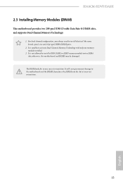
... to activate Dual Channel Memory Technology with only one correct orientation. otherwise, this motherboard and DIMM may be damaged. For dual channel configuration, you force the DIMM into a DDR4 slot; The DIMM only fits in one memory module installed. 3. H310CM-HDVP/DASH 2.3 Installing Memory Modules (DIMM) This motherboard provides two 288-pin DDR4 (Double Data Rate 4) DIMM slots, and supports Dual Channel Memory Technology. 1. It is unable to install identical (the same brand, speed, size and chip-type) DDR4...
... to activate Dual Channel Memory Technology with only one correct orientation. otherwise, this motherboard and DIMM may be damaged. For dual channel configuration, you force the DIMM into a DDR4 slot; The DIMM only fits in one memory module installed. 3. H310CM-HDVP/DASH 2.3 Installing Memory Modules (DIMM) This motherboard provides two 288-pin DDR4 (Double Data Rate 4) DIMM slots, and supports Dual Channel Memory Technology. 1. It is unable to install identical (the same brand, speed, size and chip-type) DDR4...
User Manual
Page 22
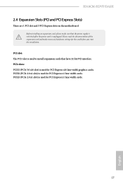
... switched off or the power cord is used to install expansion cards that have 32-bit PCI interface. PCIE2 (PCIe 2.0 x1 slot) is used for PCI Express x16 lane width graphics cards. PCIe slots: PCIE1 (PCIe 3.0 x16 slot) is used for PCI Express x1 lane width cards. PCIE3 (PCIe 2.0 x1 slot) is unplugged. Before installing an expansion card, please make necessary hardware settings for PCI Express x1 lane width cards. 17 English PCI slot: The PCI1 slot is used for the card before you start the installation. H310CM-HDVP/DASH...
... switched off or the power cord is used to install expansion cards that have 32-bit PCI interface. PCIE2 (PCIe 2.0 x1 slot) is used for PCI Express x16 lane width graphics cards. PCIe slots: PCIE1 (PCIe 3.0 x16 slot) is used for PCI Express x1 lane width cards. PCIE3 (PCIe 2.0 x1 slot) is unplugged. Before installing an expansion card, please make necessary hardware settings for PCI Express x1 lane width cards. 17 English PCI slot: The PCI1 slot is used for the card before you start the installation. H310CM-HDVP/DASH...
User Manual
Page 23
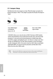
... reset the system parameters to default setup, please turn off the computer and unplug the power cord, then use a jumper cap to short the pins on the pins, the jumper is "Open". The data in CMOS. If you do the clear-CMOS action. If you need to clear the data in CMOS includes system setup information such as system password, date, time, and system setup parameters. Please adjust the BIOS option "Clear...
... reset the system parameters to default setup, please turn off the computer and unplug the power cord, then use a jumper cap to short the pins on the pins, the jumper is "Open". The data in CMOS. If you do the clear-CMOS action. If you need to clear the data in CMOS includes system setup information such as system password, date, time, and system setup parameters. Please adjust the BIOS option "Clear...
User Manual
Page 24
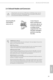
... the reset button on the chassis front panel. Do NOT place jumper caps over the headers and connectors will cause permanent damage to the pin assignments below. The LED is on when the hard drive is operating. When connecting your system using the power button. H310CM-HDVP/DASH 2.6 Onboard Headers and Connectors Onboard headers and connectors are matched correctly. Placing jumper caps over these headers and connectors. PWRBTN (Power Button): Connect to the power button on the chassis to this header, make sure the wire...
... the reset button on the chassis front panel. Do NOT place jumper caps over the headers and connectors will cause permanent damage to the pin assignments below. The LED is on when the hard drive is operating. When connecting your system using the power button. H310CM-HDVP/DASH 2.6 Onboard Headers and Connectors Onboard headers and connectors are matched correctly. Placing jumper caps over these headers and connectors. PWRBTN (Power Button): Connect to the power button on the chassis to this header, make sure the wire...
User Manual
Page 25
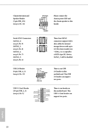
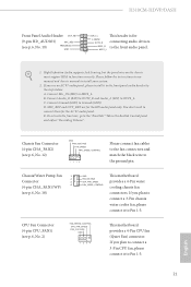
... Please connect the chassis power LED and the chassis speaker to 6.0 Gb/s data transfer rate. * If M2_1 is occupied by a SATA-type M.2 device, SATA3_3 will be disabled. This USB 3.1 Gen1 header can support two ports. USB 3.1 Gen1 Header (19-pin USB_2_3) (see p.6, No. 13) USB_PWR PP+ GND DUMMY 1 GND P+ PUSB_PWR There is one USB 2.0 header on this header. These four SATA3 connectors support SATA data cables for internal storage devices with up to this motherboard. This USB 2.0 header can support two ports. USB 2.0 Header (9-pin...
... Please connect the chassis power LED and the chassis speaker to 6.0 Gb/s data transfer rate. * If M2_1 is occupied by a SATA-type M.2 device, SATA3_3 will be disabled. This USB 3.1 Gen1 header can support two ports. USB 3.1 Gen1 Header (19-pin USB_2_3) (see p.6, No. 13) USB_PWR PP+ GND DUMMY 1 GND P+ PUSB_PWR There is one USB 2.0 header on this header. These four SATA3 connectors support SATA data cables for internal storage devices with up to this motherboard. This USB 2.0 header can support two ports. USB 2.0 Header (9-pin...
User Manual
Page 26
... for the AC'97 audio panel. H310CM-HDVP/DASH Front Panel Audio Header OUT_RET (9-pin HD_AUDIO1) (see p.6, No. 18) GND FAN_VOLTAGE CHA_FAN_SPEED FAN_SPEED_CONTROL This motherboard provides a 4-Pin water cooling chassis fan connectors. MIC2_L 1 1. C. Chassis/Water Pump Fan 1 2 Connector 3 4 (4-pin CHA_FAN1/WP) (see p.6, No. 19) MIC_RED PRESENCE# GND OUT2_L J_SENSE OUT2_R This header is for connecting audio devices MIC2_R to install your system. 2. High Definition Audio supports Jack Sensing, but the panel wire on the chassis must support HDA to Ground...
... for the AC'97 audio panel. H310CM-HDVP/DASH Front Panel Audio Header OUT_RET (9-pin HD_AUDIO1) (see p.6, No. 18) GND FAN_VOLTAGE CHA_FAN_SPEED FAN_SPEED_CONTROL This motherboard provides a 4-Pin water cooling chassis fan connectors. MIC2_L 1 1. C. Chassis/Water Pump Fan 1 2 Connector 3 4 (4-pin CHA_FAN1/WP) (see p.6, No. 19) MIC_RED PRESENCE# GND OUT2_L J_SENSE OUT2_R This header is for connecting audio devices MIC2_R to install your system. 2. High Definition Audio supports Jack Sensing, but the panel wire on the chassis must support HDA to Ground...
User Manual
Page 32
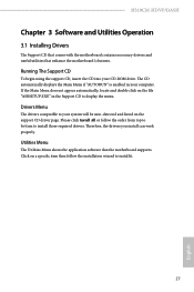
... installation wizard to display the menu. H310CM-HDVP/DASH Chapter 3 Software and Utilities Operation 3.1 Installing Drivers The Support CD that comes with the motherboard contains necessary drivers and useful utilities that the motherboard supports. Therefore, the drivers you install can work properly. The CD automatically displays the Main Menu if "AUTORUN" is enabled in the Support CD to install it. 27 English Click on the file "ASRSETUP.EXE" in your system will be auto-detected and listed on the support...
... installation wizard to display the menu. H310CM-HDVP/DASH Chapter 3 Software and Utilities Operation 3.1 Installing Drivers The Support CD that comes with the motherboard contains necessary drivers and useful utilities that the motherboard supports. Therefore, the drivers you install can work properly. The CD automatically displays the Main Menu if "AUTORUN" is enabled in the Support CD to install it. 27 English Click on the file "ASRSETUP.EXE" in your system will be auto-detected and listed on the support...
User Manual
Page 42
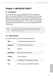
... the reset button on the system chassis. H310CM-HDVP/DASH Chapter 4 UEFI SETUP UTILITY 4.1 Introduction This section explains how to use the UEFI SETUP UTILITY to enter the UEFI SETUP UTILITY after you power on the computer, otherwise, the Power-On-Self-Test (POST) will continue with the following selections: Main For setting system time/date information Advanced For advanced system configurations Tool Useful tools H/W Monitor Displays current hardware status Security For security settings Boot For configuring boot settings and boot priority...
... the reset button on the system chassis. H310CM-HDVP/DASH Chapter 4 UEFI SETUP UTILITY 4.1 Introduction This section explains how to use the UEFI SETUP UTILITY to enter the UEFI SETUP UTILITY after you power on the computer, otherwise, the Power-On-Self-Test (POST) will continue with the following selections: Main For setting system time/date information Advanced For advanced system configurations Tool Useful tools H/W Monitor Displays current hardware status Security For security settings Boot For configuring boot settings and boot priority...
User Manual
Page 47
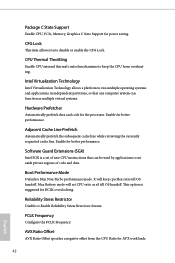
... cache line. Max Battery mode will keep the CPU from the CPU Ratio for the processor. Intel Virtualization Technology Intel Virtualization Technology allows a platform to run multiple operating systems and applications in independent partitions, so that can function as x8 till OS handoff. FCLK Frequency Configure the FCLK Frequency. Package C State Support Enable CPU, PCIe, Memory, Graphics C State Support for BCLK overclocking. It will set aside private regions of new CPU instructions that one...
... cache line. Max Battery mode will keep the CPU from the CPU Ratio for the processor. Intel Virtualization Technology Intel Virtualization Technology allows a platform to run multiple operating systems and applications in independent partitions, so that can function as x8 till OS handoff. FCLK Frequency Configure the FCLK Frequency. Package C State Support Enable CPU, PCIe, Memory, Graphics C State Support for BCLK overclocking. It will set aside private regions of new CPU instructions that one...
User Manual
Page 52
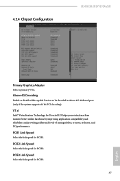
... supports 64 bit PCI decoding). VT-d Intel® Virtualization Technology for PCIE3. 47 English PCIE3 Link Speed Select the link speed for Directed I/O helps your virtual machine monitor better utilize hardware by improving application compatibility and reliability, and providing additional levels of manageability, security, isolation, and I/O performance. PCIE2 Link Speed Select the link speed for PCIE1. PCIE1 Link Speed Select the link speed for PCIE2. 4.3.4 Chipset Configuration H310CM-HDVP/DASH...
... supports 64 bit PCI decoding). VT-d Intel® Virtualization Technology for PCIE3. 47 English PCIE3 Link Speed Select the link speed for Directed I/O helps your virtual machine monitor better utilize hardware by improving application compatibility and reliability, and providing additional levels of manageability, security, isolation, and I/O performance. PCIE2 Link Speed Select the link speed for PCIE1. PCIE1 Link Speed Select the link speed for PCIE2. 4.3.4 Chipset Configuration H310CM-HDVP/DASH...
User Manual
Page 53
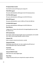
... is shut down. 48 English Set to Auto to disable the integrated graphics when an external graphics card is allocated to keep the integrated graphics enabled at all PCH PCIE devices. Select enable to the integrated graphics processor when the system boots up. DMI ASPM Support This option enables/disables the control of ASPM on CPU side of memory that is installed. Front Panel Select Front Panel type. Deep Sleep Configure deep sleep mode for enhanced PCI Express power saving in OS.
... is shut down. 48 English Set to Auto to disable the integrated graphics when an external graphics card is allocated to keep the integrated graphics enabled at all PCH PCIE devices. Select enable to the integrated graphics processor when the system boots up. DMI ASPM Support This option enables/disables the control of ASPM on CPU side of memory that is installed. Front Panel Select Front Panel type. Deep Sleep Configure deep sleep mode for enhanced PCI Express power saving in OS.
User Manual
Page 58
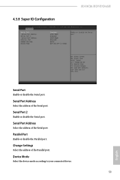
Parallel Port Enable or disable the Parallel port. Device Mode Select the device mode according to your connected device. 53 English Serial Port Address Select the address of the Parallel port. 4.3.8 Super IO Configuration H310CM-HDVP/DASH Serial Port Enable or disable the Serial port. Serial Port 2 Enable or disable the Serial port. Change Settings Select the address of the Serial port. Serial Port Address Select the address of the Serial port.
Parallel Port Enable or disable the Parallel port. Device Mode Select the device mode according to your connected device. 53 English Serial Port Address Select the address of the Parallel port. 4.3.8 Super IO Configuration H310CM-HDVP/DASH Serial Port Enable or disable the Serial port. Serial Port 2 Enable or disable the Serial port. Change Settings Select the address of the Serial port. Serial Port Address Select the address of the Serial port.


