User Manual
Page 3
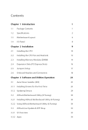
... 1.2 Specifications 2 1.3 Motherboard Layout 6 1.4 I/O Panel 8 Chapter 2 Installation 9 2.1 Installing the CPU 10 2.2 Installing the CPU Fan and Heatsink 13 2.3 Installing Memory Modules (DIMM) 14 2.4 Expansion Slots (PCI Express Slots) 16 2.5 Jumpers Setup 17 2.6 Onboard Headers and Connectors 18 Chapter 3 Software and Utilities Operation 25 3.1 Auto Driver Installer (ADI) 25 3.1.1 Installing Drivers for the First Time 25 3.1.2 Updating Drivers 29 3.2 ASRock Motherboard Utility (A-Tuning) 30 3.2.1 Installing ASRock Motherboard Utility (A-Tuning) 30 3.2.2 Using...
... 1.2 Specifications 2 1.3 Motherboard Layout 6 1.4 I/O Panel 8 Chapter 2 Installation 9 2.1 Installing the CPU 10 2.2 Installing the CPU Fan and Heatsink 13 2.3 Installing Memory Modules (DIMM) 14 2.4 Expansion Slots (PCI Express Slots) 16 2.5 Jumpers Setup 17 2.6 Onboard Headers and Connectors 18 Chapter 3 Software and Utilities Operation 25 3.1 Auto Driver Installer (ADI) 25 3.1.1 Installing Drivers for the First Time 25 3.1.2 Updating Drivers 29 3.2 ASRock Motherboard Utility (A-Tuning) 30 3.2.1 Installing ASRock Motherboard Utility (A-Tuning) 30 3.2.2 Using...
User Manual
Page 4
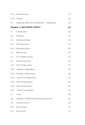
... BIOS & Drivers 37 3.3.4 Setting 38 3.4 Enabling USB Ports for Windows® 7 Installation 39 Chapter 4 UEFI SETUP UTILITY 42 4.1 Introduction 42 4.2 EZ Mode 43 4.3 Advanced Mode 44 4.3.1 UEFI Menu Bar 44 4.3.2 Navigation Keys 45 4.4 Main Screen 46 4.5 OC Tweaker Screen 47 4.6 Advanced Screen 55 4.6.1 CPU Configuration 56 4.6.2 Chipset Configuration 58 4.6.3 Storage Configuration 60 4.6.4 Super IO Configuration 61 4.6.5 ACPI Configuration 62 4.6.6 USB Configuration 64 4.6.7 Trusted Computing 65 4.7 Tools 66 4.8 Hardware Health Event Monitoring Screen...
... BIOS & Drivers 37 3.3.4 Setting 38 3.4 Enabling USB Ports for Windows® 7 Installation 39 Chapter 4 UEFI SETUP UTILITY 42 4.1 Introduction 42 4.2 EZ Mode 43 4.3 Advanced Mode 44 4.3.1 UEFI Menu Bar 44 4.3.2 Navigation Keys 45 4.4 Main Screen 46 4.5 OC Tweaker Screen 47 4.6 Advanced Screen 55 4.6.1 CPU Configuration 56 4.6.2 Chipset Configuration 58 4.6.3 Storage Configuration 60 4.6.4 Super IO Configuration 61 4.6.5 ACPI Configuration 62 4.6.6 USB Configuration 64 4.6.7 Trusted Computing 65 4.7 Tools 66 4.8 Hardware Health Event Monitoring Screen...
User Manual
Page 5
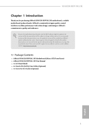
... • ASRock H310CM-HDV/M.2 SE Motherboard (Micro ATX Form Factor) • ASRock H310CM-HDV/M.2 SE User Manual • 1 x I/O Panel Shield • 2 x Serial ATA (SATA) Data Cables (Optional) • 1 x Screw for purchasing ASRock H310CM-HDV/M.2 SE motherboard, a reliable motherboard produced under ASRock's consistently stringent quality control. In case any modifications of this motherboard, please visit our website for specific information about the model you for M.2 Socket (Optional) 1 English Because the motherboard specifications and the BIOS software might be updated, the...
... • ASRock H310CM-HDV/M.2 SE Motherboard (Micro ATX Form Factor) • ASRock H310CM-HDV/M.2 SE User Manual • 1 x I/O Panel Shield • 2 x Serial ATA (SATA) Data Cables (Optional) • 1 x Screw for purchasing ASRock H310CM-HDV/M.2 SE motherboard, a reliable motherboard produced under ASRock's consistently stringent quality control. In case any modifications of this motherboard, please visit our website for specific information about the model you for M.2 Socket (Optional) 1 English Because the motherboard specifications and the BIOS software might be updated, the...

User Manual
Page 7
...) • 2 x USB 3.2 Gen1 Ports (Supports ESD Protection) • 1 x RJ-45 LAN Port with max. resolution up to 1920x1200 @ 60Hz • Supports Auto Lip Sync, Deep Color (12bpc), xvYCC and HBR (High Bit Rate Audio) with HDMI 1.4 Port (Compliant HDMI monitor is occupied by a SATA-type M.2 device, SATA3_3 will be disabled. • 1 x Ultra M.2 Socket (M2_1), supports M Key type 2280 M.2 SATA3 6.0 Gb/s module and M.2 PCI Express module up to Gen3 x4 (32 Gb/s)** ** Supports NVMe SSD as boot disks English 3
...) • 2 x USB 3.2 Gen1 Ports (Supports ESD Protection) • 1 x RJ-45 LAN Port with max. resolution up to 1920x1200 @ 60Hz • Supports Auto Lip Sync, Deep Color (12bpc), xvYCC and HBR (High Bit Rate Audio) with HDMI 1.4 Port (Compliant HDMI monitor is occupied by a SATA-type M.2 device, SATA3_3 will be disabled. • 1 x Ultra M.2 Socket (M2_1), supports M Key type 2280 M.2 SATA3 6.0 Gb/s module and M.2 PCI Express module up to Gen3 x4 (32 Gb/s)** ** Supports NVMe SSD as boot disks English 3

User Manual
Page 8
... use. • 1 x 24 pin ATX Power Connector • 1 x 8 pin 12V Power Connector • 1 x Front Panel Audio Connector • 2 x USB 2.0 Headers (Support 4 USB 2.0 ports) (Supports ESD Protection) • 1 x USB 3.2 Gen1 Header (Supports 2 USB 3.2 Gen1 ports) (Supports ESD Protection) * USB_7_8 is required) English 4 Please refer to page 25 for more detailed instructions. BIOS Feature • AMI UEFI Legal BIOS with multilingual GUI support OS • Microsoft® Windows® 11 64-bit / 10 64-bit (For 9th, 8th and 7th Gen Intel® CPU...
... use. • 1 x 24 pin ATX Power Connector • 1 x 8 pin 12V Power Connector • 1 x Front Panel Audio Connector • 2 x USB 2.0 Headers (Support 4 USB 2.0 ports) (Supports ESD Protection) • 1 x USB 3.2 Gen1 Header (Supports 2 USB 3.2 Gen1 ports) (Supports ESD Protection) * USB_7_8 is required) English 4 Please refer to page 25 for more detailed instructions. BIOS Feature • AMI UEFI Legal BIOS with multilingual GUI support OS • Microsoft® Windows® 11 64-bit / 10 64-bit (For 9th, 8th and 7th Gen Intel® CPU...

User Manual
Page 11
...Fan Connector (CHA_FAN1/WP) 5 ATX Power Connector (ATXPWR1) 6 USB 2.0 Header (USB_7_8) 7 USB 3.2 Gen1 Header (USB32_3_4) 8 SATA3 Connector (SATA3_2) (Upper), SATA3 Connector (SATA3_3) (Lower) 9 Clear CMOS Jumper (CLRMOS1) 10 SATA3 Connector (SATA3_0) (Upper), SATA3 Connector (SATA3_1) (Lower) 11 Chassis/Water Pump Fan Connector (CHA_FAN2/WP) 12 System Panel Header (PANEL1) 13 Chassis Intrusion and Speaker Header (SPK_CI1) 14 USB 2.0 Header (USB_5_6) 15 COM Port Header (COM1) 16 Print Port Header (LPT1) 17 TPM Header (TPMS1) 18 Front Panel Audio Header (HD_AUDIO1) 7 English H310CM-HDV/M.2 SE...
...Fan Connector (CHA_FAN1/WP) 5 ATX Power Connector (ATXPWR1) 6 USB 2.0 Header (USB_7_8) 7 USB 3.2 Gen1 Header (USB32_3_4) 8 SATA3 Connector (SATA3_2) (Upper), SATA3 Connector (SATA3_3) (Lower) 9 Clear CMOS Jumper (CLRMOS1) 10 SATA3 Connector (SATA3_0) (Upper), SATA3 Connector (SATA3_1) (Lower) 11 Chassis/Water Pump Fan Connector (CHA_FAN2/WP) 12 System Panel Header (PANEL1) 13 Chassis Intrusion and Speaker Header (SPK_CI1) 14 USB 2.0 Header (USB_5_6) 15 COM Port Header (COM1) 16 Print Port Header (LPT1) 17 TPM Header (TPMS1) 18 Front Panel Audio Header (HD_AUDIO1) 7 English H310CM-HDV/M.2 SE...

User Manual
Page 21
... BIOS option "Clear Status" to remove the jumper cap after clearing the CMOS. If no jumper cap is placed on the pins, the jumper is "Short". To clear and reset the system parameters to default setup, please turn off the computer and unplug the power cord, then use a jumper cap to short the pins on the pins, the jumper is "Open". If you do the clear-CMOS action. If you need to clear the data in CMOS...
... BIOS option "Clear Status" to remove the jumper cap after clearing the CMOS. If no jumper cap is placed on the pins, the jumper is "Short". To clear and reset the system parameters to default setup, please turn off the computer and unplug the power cord, then use a jumper cap to short the pins on the pins, the jumper is "Open". If you do the clear-CMOS action. If you need to clear the data in CMOS...

User Manual
Page 23
... SATA3_3 These four SATA3 connectors support SATA data cables for internal storage devices with USB32_3_4. Vbus IntA_PA_D+ IntA_PA_DGND IntA_PA_SSTX+ IntA_PA_SSTXGND IntA_PA_SSRX+ IntA_PA_SSRX- GND IntA_PB_SSRX+ IntA_PB_SSRX- Each USB 2.0 header can support two ports. * USB_7_8 is shared with up to this header. English 19 H310CM-HDV/M.2 SE Chassis Intrusion and Speaker Header (7-pin SPK_CI1) (see p.6, No. 13) SPEAKER DUMMY DUMMY +5V 1 SIGNAL GND DUMMY Please connect the chassis intrusion and the chassis speaker to 6.0 Gb/s data...
... SATA3_3 These four SATA3 connectors support SATA data cables for internal storage devices with USB32_3_4. Vbus IntA_PA_D+ IntA_PA_DGND IntA_PA_SSTX+ IntA_PA_SSTXGND IntA_PA_SSRX+ IntA_PA_SSRX- GND IntA_PB_SSRX+ IntA_PB_SSRX- Each USB 2.0 header can support two ports. * USB_7_8 is shared with up to this header. English 19 H310CM-HDV/M.2 SE Chassis Intrusion and Speaker Header (7-pin SPK_CI1) (see p.6, No. 13) SPEAKER DUMMY DUMMY +5V 1 SIGNAL GND DUMMY Please connect the chassis intrusion and the chassis speaker to 6.0 Gb/s data...

User Manual
Page 25
... print port cable that allows convenient connection of printer devices. English 21 This COM1 header supports a serial port module. Print Port Header (25-pin LPT1) (see p.6, No. 17) GND SERIRQ # S_PWRDWN # GN D LAD1 LAD2 SMB_DATA_MAIN SMB_CLK_MAIN GN D +3VS B LAD0 +3V LAD3 PCIRST # FRAM E PCICLK GN D This connector supports Trusted Platform Module (TPM) system, 1 which can securely store keys, digital certificates, passwords, and data. H310CM-HDV/M.2 SE ATX Power Connector (24-pin ATXPWR1...
... print port cable that allows convenient connection of printer devices. English 21 This COM1 header supports a serial port module. Print Port Header (25-pin LPT1) (see p.6, No. 17) GND SERIRQ # S_PWRDWN # GN D LAD1 LAD2 SMB_DATA_MAIN SMB_CLK_MAIN GN D +3VS B LAD0 +3V LAD3 PCIRST # FRAM E PCICLK GN D This connector supports Trusted Platform Module (TPM) system, 1 which can securely store keys, digital certificates, passwords, and data. H310CM-HDV/M.2 SE ATX Power Connector (24-pin ATXPWR1...

User Manual
Page 29
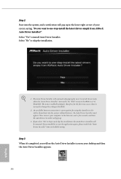
H310CM-HDV/M.2 SE Chapter 3 Software and Utilities Operation 3.1 Auto Driver Installer (ADI) Optical drive or driver DVD is required during the following procedures. Please note that the Internet access is no longer needed for the First Time Follow the instructions to install all necessary drivers automatically. 3.1.1 Installing Drivers for driver installation. Step 1 After you finish installing the operation system, simply use the Auto Driver Installer to the Internet. ASRock motherboard already has its Ethernet driver prepacked in BIOS ROM. When...
H310CM-HDV/M.2 SE Chapter 3 Software and Utilities Operation 3.1 Auto Driver Installer (ADI) Optical drive or driver DVD is required during the following procedures. Please note that the Internet access is no longer needed for the First Time Follow the instructions to install all necessary drivers automatically. 3.1.1 Installing Drivers for driver installation. Step 1 After you finish installing the operation system, simply use the Auto Driver Installer to the Internet. ASRock motherboard already has its Ethernet driver prepacked in BIOS ROM. When...
User Manual
Page 30
..., please enable the "Auto Driver Installer" item in the BIOS setting. An available Internet connection is a prerequisite for users to install drivers only when the "Auto Driver Installer" item under the "Tool" menu in the BIOS is enabled by default; If you will be removed. The Auto Driver Installer will automatically pop up for using the Auto Driver Installer. Step 3 When it's completed, you would like to change the setting in the BIOS. 2. The item is set to the...
..., please enable the "Auto Driver Installer" item in the BIOS setting. An available Internet connection is a prerequisite for users to install drivers only when the "Auto Driver Installer" item under the "Tool" menu in the BIOS is enabled by default; If you will be removed. The Auto Driver Installer will automatically pop up for using the Auto Driver Installer. Step 3 When it's completed, you would like to change the setting in the BIOS. 2. The item is set to the...

User Manual
Page 31
H310CM-HDV/M.2 SE Step 4 The Auto Driver Installer panel lists all available drivers that your selections. If you would like to start downloading and installing drivers. Select one or more drivers to be installed, click "Finish" to exit. Click "Update" to run the application again, please enable the "Auto Driver Installer" item in the BIOS setting. 27 English If there are no drivers to remove all items. Click "Unselect All" to be installed. Click "Select All" to select all of your motherboard supports.
H310CM-HDV/M.2 SE Step 4 The Auto Driver Installer panel lists all available drivers that your selections. If you would like to start downloading and installing drivers. Select one or more drivers to be installed, click "Finish" to exit. Click "Update" to run the application again, please enable the "Auto Driver Installer" item in the BIOS setting. 27 English If there are no drivers to remove all items. Click "Unselect All" to be installed. Click "Select All" to select all of your motherboard supports.
User Manual
Page 32
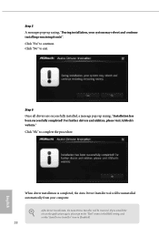
... to the "Tool" menu in the BIOS setting, and set the "Auto Driver Installer" item to continue. Click "Yes" to [Enabled]. 28 English Step 6 Once all drivers are successfully installed, a message pops up saying, "During installation, your computer. For further drivers and utilities, please visit ASRock's website." Click "Ok" to exit. After driver installation, the Auto Driver Installer will be removed. Step 5 A messages pops up saying, "Installation has been successfully completed...
... to the "Tool" menu in the BIOS setting, and set the "Auto Driver Installer" item to continue. Click "Yes" to [Enabled]. 28 English Step 6 Once all drivers are successfully installed, a message pops up saying, "During installation, your computer. For further drivers and utilities, please visit ASRock's website." Click "Ok" to exit. After driver installation, the Auto Driver Installer will be removed. Step 5 A messages pops up saying, "Installation has been successfully completed...
User Manual
Page 33
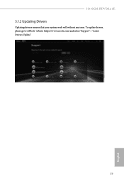
H310CM-HDV/M.2 SE 3.1.2 Updating Drivers Updating drivers ensures that your system work well without any issue. To update drivers, please go to ASRock' website (https://www.asrock.com) and select "Support" > "Latest Drivers Update". 29 English
H310CM-HDV/M.2 SE 3.1.2 Updating Drivers Updating drivers ensures that your system work well without any issue. To update drivers, please go to ASRock' website (https://www.asrock.com) and select "Support" > "Latest Drivers Update". 29 English
User Manual
Page 43
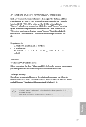
.../2 ports and PS/2 Keyboard or mouse on their support for the Enhanced Host Controller Interface (EHCI - To improve Windows 7 compatibility, please download and install the following hot fix provided by Microsoft. H310CM-HDV/M.2 SE 3.4 Enabling USB Ports for Windows® 7 Installation Intel® new processors have an optical disc drive, please find it difficult to install Windows 7 operating system because the USB ports on your computer, you do not have removed removed their motherboard won't work...
.../2 ports and PS/2 Keyboard or mouse on their support for the Enhanced Host Controller Interface (EHCI - To improve Windows 7 compatibility, please download and install the following hot fix provided by Microsoft. H310CM-HDV/M.2 SE 3.4 Enabling USB Ports for Windows® 7 Installation Intel® new processors have an optical disc drive, please find it difficult to install Windows 7 operating system because the USB ports on your computer, you do not have removed removed their motherboard won't work...

User Manual
Page 62
... Enable or disable 64bit capable Devices to be decoded in OS. PCI Express Native Control 58 Select Enable for enhanced PCI Express power saving in Above 4G Address Space (only if the system supports 64 bit PCI decoding). 4.6.2 Chipset Configuration Primary Graphics Adapter Select a primary VGA. PCIE1 Link Speed Select the link speed for PCIE3. PCIE3 Link Speed Select the link speed for PCIE1. VT-d Intel® Virtualization Technology for PCIE2. PCIE2 Link Speed...
... Enable or disable 64bit capable Devices to be decoded in OS. PCI Express Native Control 58 Select Enable for enhanced PCI Express power saving in Above 4G Address Space (only if the system supports 64 bit PCI decoding). 4.6.2 Chipset Configuration Primary Graphics Adapter Select a primary VGA. PCIE1 Link Speed Select the link speed for PCIE3. PCIE3 Link Speed Select the link speed for PCIE1. VT-d Intel® Virtualization Technology for PCIE2. PCIE2 Link Speed...

User Manual
Page 63
... a power failure. If [Power Off] is selected, the system will remain off when the power recovers. PCH PCIE ASPM Support This option enables/disables the ASPM support for all CPU downstream devices. Inte(R) Ethernet Connection I219-V Enable or disable the onboard network interface controller (Intel® I219V). Front Panel Enable/disable front panel HD audio. Select enable to enable onboard HD audio and automatically disable it when a sound card is shut down. Deep Sleep Configure deep sleep mode for power saving when the computer is installed. H310CM-HDV/M.2 SE PCIE...
... a power failure. If [Power Off] is selected, the system will remain off when the power recovers. PCH PCIE ASPM Support This option enables/disables the ASPM support for all CPU downstream devices. Inte(R) Ethernet Connection I219-V Enable or disable the onboard network interface controller (Intel® I219V). Front Panel Enable/disable front panel HD audio. Select enable to enable onboard HD audio and automatically disable it when a sound card is shut down. Deep Sleep Configure deep sleep mode for power saving when the computer is installed. H310CM-HDV/M.2 SE PCIE...

User Manual
Page 65
Parallel Port Enable or disable the Parallel port. 4.6.4 Super IO Configuration H310CM-HDV/M.2 SE Serial Port Enable or disable the Serial port. Change Settings Select the address of the Serial port. PS2 Y-Cable Enable the PS2 Y-Cable or set this option to your connected device. Device Mode Select the device mode according to Auto. 61 English Serial Port Address Select the address of the Parallel port.
Parallel Port Enable or disable the Parallel port. 4.6.4 Super IO Configuration H310CM-HDV/M.2 SE Serial Port Enable or disable the Serial port. Change Settings Select the address of the Serial port. PS2 Y-Cable Enable the PS2 Y-Cable or set this option to your connected device. Device Mode Select the device mode according to Auto. 61 English Serial Port Address Select the address of the Parallel port.
User Manual
Page 70
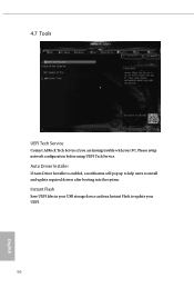
4.7 Tools UEFI Tech Service Contact ASRock Tech Service if you are having trouble with your UEFI. 66 English Instant Flash Save UEFI files in your USB storage device and run Instant Flash to install and update required drivers after booting into the system. Auto Driver Installer If Auto Driver Installer is enabled, a notification will pop up to help users to update your PC. Please setup network configuration before using UEFI Tech Service.
4.7 Tools UEFI Tech Service Contact ASRock Tech Service if you are having trouble with your UEFI. 66 English Instant Flash Save UEFI files in your USB storage device and run Instant Flash to install and update required drivers after booting into the system. Auto Driver Installer If Auto Driver Installer is enabled, a notification will pop up to help users to update your PC. Please setup network configuration before using UEFI Tech Service.
User Manual
Page 73
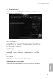
... press enter to change the password for the system. You may set or change the password for Secure Boot. User Password Set or change the supervisor/user password for the administrator account. Users are unable to remove the password. Intel(R) Platform Trust Technology Enable/disable Intel PTT in ME. Disable this option to remove the password. Leave it blank and press enter to use discrete TPM Module. 69 English Supervisor Password Set or change the settings in the UEFI Setup Utility. H310CM-HDV/M.2 SE 4.9 Security Screen...
... press enter to change the password for the system. You may set or change the password for Secure Boot. User Password Set or change the supervisor/user password for the administrator account. Users are unable to remove the password. Intel(R) Platform Trust Technology Enable/disable Intel PTT in ME. Disable this option to remove the password. Leave it blank and press enter to use discrete TPM Module. 69 English Supervisor Password Set or change the settings in the UEFI Setup Utility. H310CM-HDV/M.2 SE 4.9 Security Screen...


