Intel Rapid Storage Guide
Page 13
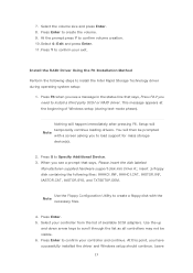
... the status line that says, Please insert the disk labeled Manufacturer-supplied hardware support disk into Drive A:, insert ;a floppy disk containing the following steps to install the Intel Rapid Storage Technology driver during text-mode phase). Press Enter to confirm volume creation. 10. Select 4: Exit and press Enter. 11. Install the RAID Driver Using the F6 Installation Method Perform the following files: IAAHCI.INF, IAAHCI.CAT, IASTOR.INF, IASTOR.CAT...
... the status line that says, Please insert the disk labeled Manufacturer-supplied hardware support disk into Drive A:, insert ;a floppy disk containing the following steps to install the Intel Rapid Storage Technology driver during text-mode phase). Press Enter to confirm volume creation. 10. Select 4: Exit and press Enter. 11. Install the RAID Driver Using the F6 Installation Method Perform the following files: IAAHCI.INF, IAAHCI.CAT, IASTOR.INF, IASTOR.CAT...

Intel Rapid Storage Guide
Page 16
... a floppy disk with a screen asking you need to use the Floppy Configuration Utility to Specify Additional Device. 3. Setup will happen immediately after pressing F6. You will then be used to load the Intel® Rapid Storage Technology driver during operating system installation. When you see a message in RAID mode or AHCI mode, the F6 installation method must be prompted with the necessary files. You can use a USB floppy drive or create a slipstream version of Windows setup (during text-mode...
... a floppy disk with a screen asking you need to use the Floppy Configuration Utility to Specify Additional Device. 3. Setup will happen immediately after pressing F6. You will then be used to load the Intel® Rapid Storage Technology driver during operating system installation. When you see a message in RAID mode or AHCI mode, the F6 installation method must be prompted with the necessary files. You can use a USB floppy drive or create a slipstream version of Windows setup (during text-mode...

RAID Installation Guide
Page 7
... BIOS RAID Items After installing the hard disk drives, please set the necessary RAID items in your RAID configuration. Press to set SATA Mode Selection to your system, and press key to complete the process. Go to Advanced Storage Configuration and set RAID configuration. STEP 2: Use ASRock Easy RAID Installer Easy RAID Installer can copy the RAID driver from a support CD to [RAID]. Boot your USB storage device with RAID functions, please follow the procedures below. Follow the onscreen instruction to enter BIOS setup utility. 2.3 Installing Windows® 10 64-bit...
... BIOS RAID Items After installing the hard disk drives, please set the necessary RAID items in your RAID configuration. Press to set SATA Mode Selection to your system, and press key to complete the process. Go to Advanced Storage Configuration and set RAID configuration. STEP 2: Use ASRock Easy RAID Installer Easy RAID Installer can copy the RAID driver from a support CD to [RAID]. Boot your USB storage device with RAID functions, please follow the procedures below. Follow the onscreen instruction to enter BIOS setup utility. 2.3 Installing Windows® 10 64-bit...
User Manual
Page 7
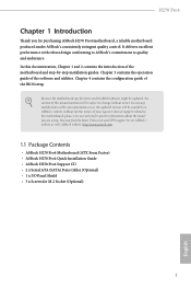
...) • ASRock H270 Pro4 Quick Installation Guide • ASRock H270 Pro4 Support CD • 2 x Serial ATA (SATA) Data Cables (Optional) • 1 x I/O Panel Shield • 3 x Screws for purchasing ASRock H270 Pro4 motherboard, a reliable motherboard produced under ASRock's consistently stringent quality control. In this motherboard, please visit our website for specific information about the model you for M.2 Socket (Optional) 1 English Chapter 3 contains the operation guide of the BIOS setup. In case any modifications of this documentation occur, the updated version will be...
...) • ASRock H270 Pro4 Quick Installation Guide • ASRock H270 Pro4 Support CD • 2 x Serial ATA (SATA) Data Cables (Optional) • 1 x I/O Panel Shield • 3 x Screws for purchasing ASRock H270 Pro4 motherboard, a reliable motherboard produced under ASRock's consistently stringent quality control. In this motherboard, please visit our website for specific information about the model you for M.2 Socket (Optional) 1 English Chapter 3 contains the operation guide of the BIOS setup. In case any modifications of this documentation occur, the updated version will be...
User Manual
Page 11
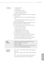
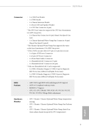
...8226; 1 x Chassis Intrusion Header • 1 x Power LED and Speaker Header • 1 x CPU Fan Connector (4-pin) * The CPU Fan Connector supports the CPU fan of maximum 1.5A (18W) fan power. * CHA_FAN2 can auto detect if 3-pin or 4-pin fan is in use. • 1 x 24 pin ATX Power Connector • 1 x 8 pin 12V Power Connector • 1 x Front Panel Audio Connector • 1 x Thunderbolt AIC Connector (5-pin) • 1 x Thunderbolt AIC Connector (10-pin) * Only one Thunderbolt AIC Card is supported. • 3 x USB 2.0 Headers (Support 5 USB 2.0 ports) (Supports ESD Protection (ASRock Full...
...8226; 1 x Chassis Intrusion Header • 1 x Power LED and Speaker Header • 1 x CPU Fan Connector (4-pin) * The CPU Fan Connector supports the CPU fan of maximum 1.5A (18W) fan power. * CHA_FAN2 can auto detect if 3-pin or 4-pin fan is in use. • 1 x 24 pin ATX Power Connector • 1 x 8 pin 12V Power Connector • 1 x Front Panel Audio Connector • 1 x Thunderbolt AIC Connector (5-pin) • 1 x Thunderbolt AIC Connector (10-pin) * Only one Thunderbolt AIC Card is supported. • 3 x USB 2.0 Headers (Support 5 USB 2.0 ports) (Supports ESD Protection (ASRock Full...

User Manual
Page 14
...288-pin DDR4 DIMM Slots (DDR4_A2, DDR4_B2) 5 CPU Fan Connector (CPU_FAN1) 6 ATX Power Connector (ATXPWR1) 7 USB 3.0 Header (USB3_3_4) 8 SATA3 Connector (SATA3_5) 9 SATA3 Connector (SATA3_4) 10 SATA3 Connector (SATA3_3) 11 SATA3 Connector (SATA3_2) 12 SATA3 Connector (SATA3_1) 13 SATA3 Connector (SATA3_0) 14 System Panel Header (PANEL1) 15 Power LED and Speaker Header (SPK_PLED1) 16 Chassis Fan / Waterpump Fan Connector (CHA_FAN3/W_PUMP) 17 Chassis Fan Connector (CHA_FAN1) 18 USB 2.0 Header (USB_3_4) 19 USB 2.0 Header (USB_5_6) 20 USB 2.0 Header (USB_7) 21 Clear CMOS Jumper (CLRMOS1) 22 Chassis...
...288-pin DDR4 DIMM Slots (DDR4_A2, DDR4_B2) 5 CPU Fan Connector (CPU_FAN1) 6 ATX Power Connector (ATXPWR1) 7 USB 3.0 Header (USB3_3_4) 8 SATA3 Connector (SATA3_5) 9 SATA3 Connector (SATA3_4) 10 SATA3 Connector (SATA3_3) 11 SATA3 Connector (SATA3_2) 12 SATA3 Connector (SATA3_1) 13 SATA3 Connector (SATA3_0) 14 System Panel Header (PANEL1) 15 Power LED and Speaker Header (SPK_PLED1) 16 Chassis Fan / Waterpump Fan Connector (CHA_FAN3/W_PUMP) 17 Chassis Fan Connector (CHA_FAN1) 18 USB 2.0 Header (USB_3_4) 19 USB 2.0 Header (USB_5_6) 20 USB 2.0 Header (USB_7) 21 Clear CMOS Jumper (CLRMOS1) 22 Chassis...

User Manual
Page 25
... update the BIOS. When the jumper cap is removed. English 19 Clear CMOS Jumper (CLRMOS1) (see p.7, No. 21) Default Clear CMOS CLRMOS1 allows you clear the CMOS, the case open may be cleared only if the CMOS battery is placed on these 2 pins. To clear and reset the system parameters to clear the record of previous chassis intrusion status. H270 Pro4 2.5 Jumpers Setup The illustration shows how jumpers are "Short" when a jumper cap is placed on the pins, the jumper...
... update the BIOS. When the jumper cap is removed. English 19 Clear CMOS Jumper (CLRMOS1) (see p.7, No. 21) Default Clear CMOS CLRMOS1 allows you clear the CMOS, the case open may be cleared only if the CMOS battery is placed on these 2 pins. To clear and reset the system parameters to clear the record of previous chassis intrusion status. H270 Pro4 2.5 Jumpers Setup The illustration shows how jumpers are "Short" when a jumper cap is placed on the pins, the jumper...

User Manual
Page 27
... six SATA3 connectors support SATA data cables for internal storage devices with up to this motherboard. USB_PWR PP+ GND DUMMY 1 GND P+ PUSB_PWR There are two USB 2.0 headers on this motherboard. English 21 Please connect the chassis power LED and the chassis speaker to 6.0 Gb/s data transfer rate. * If M2_1 is occupied by a SATAtype M.2 device, SATA3_5 will be disabled. * If M2_2 is one port. Each USB 2.0 header can support one USB 2.0 header on this header. H270 Pro4 Power LED and Speaker Header (7-pin SPK_PLED1...
... six SATA3 connectors support SATA data cables for internal storage devices with up to this motherboard. USB_PWR PP+ GND DUMMY 1 GND P+ PUSB_PWR There are two USB 2.0 headers on this motherboard. English 21 Please connect the chassis power LED and the chassis speaker to 6.0 Gb/s data transfer rate. * If M2_1 is occupied by a SATAtype M.2 device, SATA3_5 will be disabled. * If M2_2 is one port. Each USB 2.0 header can support one USB 2.0 header on this header. H270 Pro4 Power LED and Speaker Header (7-pin SPK_PLED1...

User Manual
Page 31
... the cards are AMD certified. 2. It is provided with the graphics card you to install up to use identical CrossFireXTM-ready graphics cards that are properly seated on the top of the graphics cards. (The CrossFire Bridge is recommended to three identical PCI Express x16 graphics cards. 1. Make sure that your system requires. Please refer to PCIE4 slot. H270 Pro4 2.7 CrossFireXTM and Quad CrossFireXTM Operation Guide This motherboard supports CrossFireXTM...
... the cards are AMD certified. 2. It is provided with the graphics card you to install up to use identical CrossFireXTM-ready graphics cards that are properly seated on the top of the graphics cards. (The CrossFire Bridge is recommended to three identical PCI Express x16 graphics cards. 1. Make sure that your system requires. Please refer to PCIE4 slot. H270 Pro4 2.7 CrossFireXTM and Quad CrossFireXTM Operation Guide This motherboard supports CrossFireXTM...
User Manual
Page 33
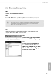
H270 Pro4 2.7.2 Driver Installation and Setup Step 1 Power on your computer. Step 3 Install the required drivers and CATALYST Control Center then restart your computer and boot into OS. Then select Enable AMD CrossFireX and click Apply. English 27 Please check AMD's website for AMD driver updates. We recommend using this utility to uninstall any VGA drivers installed in the Windows® system tray. AMD Catalyst Control Center Step 4 Double-click the AMD Catalyst Control Center icon in...
H270 Pro4 2.7.2 Driver Installation and Setup Step 1 Power on your computer. Step 3 Install the required drivers and CATALYST Control Center then restart your computer and boot into OS. Then select Enable AMD CrossFireX and click Apply. English 27 Please check AMD's website for AMD driver updates. We recommend using this utility to uninstall any VGA drivers installed in the Windows® system tray. AMD Catalyst Control Center Step 4 Double-click the AMD Catalyst Control Center icon in...
User Manual
Page 37
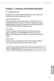
... listed on a specific item then follow the order from top to bottom to your computer. Running The Support CD To begin using the support CD, insert the CD into your CD-ROM drive. Please click Install All or follow the installation wizard to display the menu. To improve Windows 7 compatibility, please download and install the following hot fix provided by Microsoft. H270 Pro4 Chapter 3 Software and Utilities Operation 3.1 Installing Drivers The Support...
... listed on a specific item then follow the order from top to bottom to your computer. Running The Support CD To begin using the support CD, insert the CD into your CD-ROM drive. Please click Install All or follow the installation wizard to display the menu. To improve Windows 7 compatibility, please download and install the following hot fix provided by Microsoft. H270 Pro4 Chapter 3 Software and Utilities Operation 3.1 Installing Drivers The Support...
User Manual
Page 48
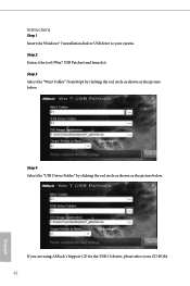
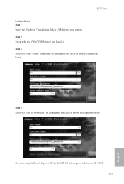
Instructions Step 1 Insert the Windows® 7 installation disk or USB drive to your CD-ROM. 42 English Step 2 Extract the tool (Win7 USB Patcher) and launch it. Step 4 Select the "USB Driver Folder" by clicking the red circle as shown as the picture below . Step 3 Select the "Win7 Folder" from Step1 by clicking the red circle as shown as the picture below . If you are using ASRock's Support CD for the USB 3.0 driver, please select your system.
Instructions Step 1 Insert the Windows® 7 installation disk or USB drive to your CD-ROM. 42 English Step 2 Extract the tool (Win7 USB Patcher) and launch it. Step 4 Select the "USB Driver Folder" by clicking the red circle as shown as the picture below . Step 3 Select the "Win7 Folder" from Step1 by clicking the red circle as shown as the picture below . If you are using ASRock's Support CD for the USB 3.0 driver, please select your system.

User Manual
Page 66
... devices failure. Onboard LAN Enable or disable the onboard network interface controller. PCIE5 Link Speed Select the link speed for enhanced PCI Express power saving in OS. PCH DMI ASPM Support This option enables/disables the ASPM support for all PCH DMI devices. IGPU Multi-Monitor Select disable to the integrated graphics processor when the system boots up. PCIE4 Link Speed Select the link speed for all times. Share Memory Configure the size of the DMI Link. Onboard HD Audio Enable/disable onboard HD audio. PCIE ASPM Support...
... devices failure. Onboard LAN Enable or disable the onboard network interface controller. PCIE5 Link Speed Select the link speed for enhanced PCI Express power saving in OS. PCH DMI ASPM Support This option enables/disables the ASPM support for all PCH DMI devices. IGPU Multi-Monitor Select disable to the integrated graphics processor when the system boots up. PCIE4 Link Speed Select the link speed for all times. Share Memory Configure the size of the DMI Link. Onboard HD Audio Enable/disable onboard HD audio. PCIE ASPM Support...
User Manual
Page 75
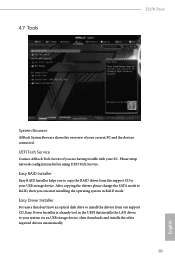
... start installing the operating system in the UEFI that don't have an optical disk drive to install the drivers from our support CD, Easy Driver Installer is a handy tool in RAID mode. Easy RAID Installer Easy RAID Installer helps you to copy the RAID driver from the support CD to RAID, then you are having trouble with your USB storage device. Please setup network configuration before using UEFI Tech Service. Easy Driver Installer For users that installs the LAN driver to your current PC and the devices connected...
... start installing the operating system in the UEFI that don't have an optical disk drive to install the drivers from our support CD, Easy Driver Installer is a handy tool in RAID mode. Easy RAID Installer Easy RAID Installer helps you to copy the RAID driver from the support CD to RAID, then you are having trouble with your USB storage device. Please setup network configuration before using UEFI Tech Service. Easy Driver Installer For users that installs the LAN driver to your current PC and the devices connected...
User Manual
Page 76
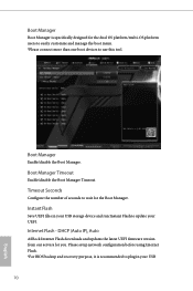
.... Instant Flash Save UEFI files in your UEFI. Please setup network configuration before using Internet Flash. *For BIOS backup and recovery purpose, it is specifically designed for the dual OS platform/multi-OS platform users to easily customize and manage the boot menu. *Please connect more than one boot devices to use this tool. Boot Manager Enable/disable the Boot Manager. Boot Manager Timeout Enable/disable the Boot Manager Timeout. DHCP (Auto IP), Auto ASRock Internet Flash downloads and updates the latest UEFI firmware version from our...
.... Instant Flash Save UEFI files in your UEFI. Please setup network configuration before using Internet Flash. *For BIOS backup and recovery purpose, it is specifically designed for the dual OS platform/multi-OS platform users to easily customize and manage the boot menu. *Please connect more than one boot devices to use this tool. Boot Manager Enable/disable the Boot Manager. Boot Manager Timeout Enable/disable the Boot Manager Timeout. DHCP (Auto IP), Auto ASRock Internet Flash downloads and updates the latest UEFI firmware version from our...

User Manual
Page 77
H270 Pro4 Internet Setting Enable or disable sound effects in the setup utility. UEFI Download Server Select a server to configure internet connection settings for Internet Flash. Network Configuration Use this function. pen drive before using this to download the UEFI firmware. 71 English
H270 Pro4 Internet Setting Enable or disable sound effects in the setup utility. UEFI Download Server Select a server to configure internet connection settings for Internet Flash. Network Configuration Use this function. pen drive before using this to download the UEFI firmware. 71 English

User Manual
Page 81
... press enter to change the password for the administrator account. Disable this option to change the password for the user account. Intel(R) Platform Trust Technology Enable/disable Intel PTT in the UEFI Setup Utility. Supervisor Password Set or change the settings in the UEFI Setup Utility. Leave it blank and press enter to enable or disable support for the system. Users are unable to use discrete TPM Module. 75 English Secure Boot Use this item to remove the password. H270 Pro4 4.9 Security Screen In...
... press enter to change the password for the administrator account. Disable this option to change the password for the user account. Intel(R) Platform Trust Technology Enable/disable Intel PTT in the UEFI Setup Utility. Supervisor Password Set or change the settings in the UEFI Setup Utility. Leave it blank and press enter to enable or disable support for the system. Users are unable to use discrete TPM Module. 75 English Secure Boot Use this item to remove the password. H270 Pro4 4.9 Security Screen In...

Quick Installation Guide
Page 4
...288-pin DDR4 DIMM Slots (DDR4_A2, DDR4_B2) 5 CPU Fan Connector (CPU_FAN1) 6 ATX Power Connector (ATXPWR1) 7 USB 3.0 Header (USB3_3_4) 8 SATA3 Connector (SATA3_5) 9 SATA3 Connector (SATA3_4) 10 SATA3 Connector (SATA3_3) 11 SATA3 Connector (SATA3_2) 12 SATA3 Connector (SATA3_1) 13 SATA3 Connector (SATA3_0) 14 System Panel Header (PANEL1) 15 Power LED and Speaker Header (SPK_PLED1) 16 Chassis Fan / Waterpump Fan Connector (CHA_FAN3/W_PUMP) 17 Chassis Fan Connector (CHA_FAN1) 18 USB 2.0 Header (USB_3_4) 19 USB 2.0 Header (USB_5_6) 20 USB 2.0 Header (USB_7) 21 Clear CMOS Jumper (CLRMOS1) 22 Chassis...
...288-pin DDR4 DIMM Slots (DDR4_A2, DDR4_B2) 5 CPU Fan Connector (CPU_FAN1) 6 ATX Power Connector (ATXPWR1) 7 USB 3.0 Header (USB3_3_4) 8 SATA3 Connector (SATA3_5) 9 SATA3 Connector (SATA3_4) 10 SATA3 Connector (SATA3_3) 11 SATA3 Connector (SATA3_2) 12 SATA3 Connector (SATA3_1) 13 SATA3 Connector (SATA3_0) 14 System Panel Header (PANEL1) 15 Power LED and Speaker Header (SPK_PLED1) 16 Chassis Fan / Waterpump Fan Connector (CHA_FAN3/W_PUMP) 17 Chassis Fan Connector (CHA_FAN1) 18 USB 2.0 Header (USB_3_4) 19 USB 2.0 Header (USB_5_6) 20 USB 2.0 Header (USB_7) 21 Clear CMOS Jumper (CLRMOS1) 22 Chassis...
Quick Installation Guide
Page 11
...8226; 1 x Chassis Intrusion Header • 1 x Power LED and Speaker Header • 1 x CPU Fan Connector (4-pin) * The CPU Fan Connector supports the CPU fan of maximum 1.5A (18W) fan power. * CHA_FAN2 can auto detect if 3-pin or 4-pin fan is in use. • 1 x 24 pin ATX Power Connector • 1 x 8 pin 12V Power Connector • 1 x Front Panel Audio Connector • 1 x Thunderbolt AIC Connector (5-pin) • 1 x Thunderbolt AIC Connector (10-pin) * Only one Thunderbolt AIC Card is supported. • 3 x USB 2.0 Headers (Support 5 USB 2.0 ports) (Supports ESD Protection (ASRock Full...
...8226; 1 x Chassis Intrusion Header • 1 x Power LED and Speaker Header • 1 x CPU Fan Connector (4-pin) * The CPU Fan Connector supports the CPU fan of maximum 1.5A (18W) fan power. * CHA_FAN2 can auto detect if 3-pin or 4-pin fan is in use. • 1 x 24 pin ATX Power Connector • 1 x 8 pin 12V Power Connector • 1 x Front Panel Audio Connector • 1 x Thunderbolt AIC Connector (5-pin) • 1 x Thunderbolt AIC Connector (10-pin) * Only one Thunderbolt AIC Card is supported. • 3 x USB 2.0 Headers (Support 5 USB 2.0 ports) (Supports ESD Protection (ASRock Full...
Quick Installation Guide
Page 169
If you are using ASRock's Support CD for the USB 3.0 driver, please select your system. Step 2 Extract the tool (Win7 USB Patcher) and launch it. Step 3 Select the "Win7 Folder" from Step1 by clicking the red circle as shown as the picture below . Step 4 Select the "USB Driver Folder" by clicking the red circle as shown as the picture below . H270 Pro4 Instructions Step 1 Insert the Windows® 7 installation disk or USB drive to your CD-ROM. 167 English
If you are using ASRock's Support CD for the USB 3.0 driver, please select your system. Step 2 Extract the tool (Win7 USB Patcher) and launch it. Step 3 Select the "Win7 Folder" from Step1 by clicking the red circle as shown as the picture below . Step 4 Select the "USB Driver Folder" by clicking the red circle as shown as the picture below . H270 Pro4 Instructions Step 1 Insert the Windows® 7 installation disk or USB drive to your CD-ROM. 167 English


