
User Manual
Page 2
...169;2016 ASRock INC. With respect to the contents of this motherboard contains Perchlorate, a toxic substance controlled in this documentation may not be constructed as a commitment by the California Legislature. CALIFORNIA, USA ONLY The Lithium battery adopted on this documentation, ASRock does ... or by the purchaser for backup purpose, without written consent of merchantability or fitness for a particular purpose. ASRock assumes no event shall ASRock, its directors, officers, employees, or agents be liable for any indirect, special, incidental, or consequential damages...
...169;2016 ASRock INC. With respect to the contents of this motherboard contains Perchlorate, a toxic substance controlled in this documentation may not be constructed as a commitment by the California Legislature. CALIFORNIA, USA ONLY The Lithium battery adopted on this documentation, ASRock does ... or by the purchaser for backup purpose, without written consent of merchantability or fitness for a particular purpose. ASRock assumes no event shall ASRock, its directors, officers, employees, or agents be liable for any indirect, special, incidental, or consequential damages...
User Manual
Page 4
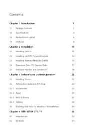
... 1 Introduction 1 1.1 Package Contents 1 1.2 Specifications 2 1.3 Motherboard Layout 6 1.4 I/O Panel 8 Chapter 2 Installation 10 2.1 Installing the CPU 11 2.2 Installing the CPU Fan and Heatsink 14 2.3 Installing Memory Modules (DIMM) 15 2.4 Expansion Slots (PCI Express Slots) 17 2.5 Onboard Headers and Connectors 18 Chapter 3 Software and Utilities Operation 22 3.1 Installing Drivers 22 3.2 ASRock Live Update & APP Shop 23...
... 1 Introduction 1 1.1 Package Contents 1 1.2 Specifications 2 1.3 Motherboard Layout 6 1.4 I/O Panel 8 Chapter 2 Installation 10 2.1 Installing the CPU 11 2.2 Installing the CPU Fan and Heatsink 14 2.3 Installing Memory Modules (DIMM) 15 2.4 Expansion Slots (PCI Express Slots) 17 2.5 Onboard Headers and Connectors 18 Chapter 3 Software and Utilities Operation 22 3.1 Installing Drivers 22 3.2 ASRock Live Update & APP Shop 23...
User Manual
Page 6
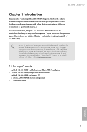
... about the model you for purchasing ASRock H110M-DS/Hyper motherboard, a reliable motherboard produced under ASRock's consistently stringent quality control. It delivers excellent performance with robust design conforming to ASRock's commitment to change without further notice. ASRock website http://www.asrock.com. 1.1 Package Contents • ASRock H110M-DS/Hyper Motherboard (Micro ATX Form Factor) • ASRock H110M-DS/Hyper Quick Installation Guide • ASRock H110M-DS/Hyper Support CD • 2 x Serial ATA (SATA...
... about the model you for purchasing ASRock H110M-DS/Hyper motherboard, a reliable motherboard produced under ASRock's consistently stringent quality control. It delivers excellent performance with robust design conforming to ASRock's commitment to change without further notice. ASRock website http://www.asrock.com. 1.1 Package Contents • ASRock H110M-DS/Hyper Motherboard (Micro ATX Form Factor) • ASRock H110M-DS/Hyper Quick Installation Guide • ASRock H110M-DS/Hyper Support CD • 2 x Serial ATA (SATA...
User Manual
Page 11
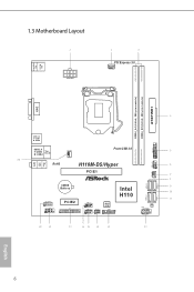
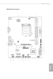
1.3 Motherboard Layout PS2 Mouse PS2 Keyboard ATX12V1 PCI Express 3.0 CPU_FAN1 DDR4_A1 (64 bit, 288-pin module) DDR4_B1 (64 bit, 288-pin module) ATXPWR1 DVI1 Top: LINE IN Center: FRONT Bottom: MIC IN USB 3.0 T: USB1 B: USB2 USB_11_12 USB 2.0 T: USB3 B: USB4 Top: RJ-45 CHA_FAN1 Front USB 3.0 1 USB_9_10 RoHS H110M-DS/Hyper 1 PCIE1 CHA_FAN2 CMOS Battery HD_AUDIO1 1 COM1 1 PCIE2 LPT1 1 Intel H110 USB_5_6 1 USB_7_8 SPK_CI1 1 1 BIOS ROM TPMS1 1 PANEL1 CLRMOS1 PLED PWRBTN 1 HDLED RESET SATA3_0 SATA3_1 SATA3_2 SATA3_3 English 6
1.3 Motherboard Layout PS2 Mouse PS2 Keyboard ATX12V1 PCI Express 3.0 CPU_FAN1 DDR4_A1 (64 bit, 288-pin module) DDR4_B1 (64 bit, 288-pin module) ATXPWR1 DVI1 Top: LINE IN Center: FRONT Bottom: MIC IN USB 3.0 T: USB1 B: USB2 USB_11_12 USB 2.0 T: USB3 B: USB4 Top: RJ-45 CHA_FAN1 Front USB 3.0 1 USB_9_10 RoHS H110M-DS/Hyper 1 PCIE1 CHA_FAN2 CMOS Battery HD_AUDIO1 1 COM1 1 PCIE2 LPT1 1 Intel H110 USB_5_6 1 USB_7_8 SPK_CI1 1 1 BIOS ROM TPMS1 1 PANEL1 CLRMOS1 PLED PWRBTN 1 HDLED RESET SATA3_0 SATA3_1 SATA3_2 SATA3_3 English 6
User Manual
Page 15
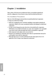
...do not touch the ICs. • Whenever you uninstall any motherboard settings. • Make sure to ensure that comes with the components. • When placing screws to secure the motherboard to the motherboard's components, NEVER place your chassis to unplug the power cord before... you install the motherboard, study the configuration of the following precautions before installing or removing the motherboard components. Doing so may cause physical injuries and damages to motherboard components. • In order to avoid damage from static...
...do not touch the ICs. • Whenever you uninstall any motherboard settings. • Make sure to ensure that comes with the components. • When placing screws to secure the motherboard to the motherboard's components, NEVER place your chassis to unplug the power cord before... you install the motherboard, study the configuration of the following precautions before installing or removing the motherboard components. Doing so may cause physical injuries and damages to motherboard components. • In order to avoid damage from static...
User Manual
Page 18
H110M-DS/Hyper Please save and replace the cover if the processor is removed. The cover must be placed if you wish to return the motherboard for after service. 13 English
H110M-DS/Hyper Please save and replace the cover if the processor is removed. The cover must be placed if you wish to return the motherboard for after service. 13 English
User Manual
Page 20
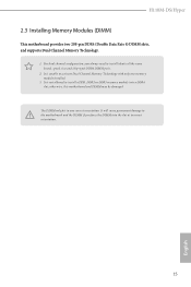
... memory module into the slot at incorrect orientation. 15 English otherwise, this motherboard and DIMM may be damaged. It will cause permanent damage to activate Dual Channel Memory Technology with only one correct orientation. H110M-DS/Hyper 2.3 Installing Memory Modules (DIMM) This motherboard provides two 288-pin DDR4 (Double Data Rate 4) DIMM slots, and supports...
... memory module into the slot at incorrect orientation. 15 English otherwise, this motherboard and DIMM may be damaged. It will cause permanent damage to activate Dual Channel Memory Technology with only one correct orientation. H110M-DS/Hyper 2.3 Installing Memory Modules (DIMM) This motherboard provides two 288-pin DDR4 (Double Data Rate 4) DIMM slots, and supports...
User Manual
Page 22
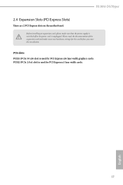
PCIE2 (PCIe 2.0 x1 slot) is used for PCI Express x16 lane width graphics cards. Before installing an expansion card, please make necessary hardware settings for PCI Express x1 lane width cards. 17 English Please read the documentation of the expansion card and make sure that the power supply is switched off or the power cord is used for the card before you start the installation. PCIe slots: PCIE1 (PCIe 3.0 x16 slot) is unplugged. H110M-DS/Hyper 2.4 Expansion Slots (PCI Express Slots) There are 2 PCI Express slots on the motherboard.
PCIE2 (PCIe 2.0 x1 slot) is used for PCI Express x16 lane width graphics cards. Before installing an expansion card, please make necessary hardware settings for PCI Express x1 lane width cards. 17 English Please read the documentation of the expansion card and make sure that the power supply is switched off or the power cord is used for the card before you start the installation. PCIe slots: PCIE1 (PCIe 3.0 x16 slot) is unplugged. H110M-DS/Hyper 2.4 Expansion Slots (PCI Express Slots) There are 2 PCI Express slots on the motherboard.
User Manual
Page 23
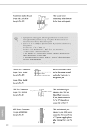
... chassis front panel. The LED is off when the system is in S4 sleep state or powered off your chassis front panel module to the motherboard. A front panel module mainly consists of power switch, reset switch, power LED, hard drive activity LED, speaker and etc. HDLED (Hard Drive Activity LED): Connect...
... chassis front panel. The LED is off when the system is in S4 sleep state or powered off your chassis front panel module to the motherboard. A front panel module mainly consists of power switch, reset switch, power LED, hard drive activity LED, speaker and etc. HDLED (Hard Drive Activity LED): Connect...
User Manual
Page 24
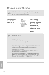
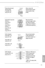
... the I/O panel, there is shared with up to this header. USB_PWR PP+ GND DUMMY 1 GND P+ PUSB_PWR There are three headers on this motherboard. Each USB 3.0 header can support two ports. Serial ATA3 Connectors (SATA3_0: see p.6, No. 8) (SATA3_1: see p.6, No. 9) (SATA3_2:...H110M-DS/Hyper Chassis Intrusion and Speaker Header (7-pin SPK_CI1) (see p.6, No. 14) SPEAKER DUMMY DUMMY +5V 1 SIGNAL GND DUMMY Please connect the chassis intrusion and the chassis speaker to 6.0 Gb/s data transfer rate. Each USB 2.0 header can support two ports. * USB_11_12 is one header on this motherboard...
... the I/O panel, there is shared with up to this header. USB_PWR PP+ GND DUMMY 1 GND P+ PUSB_PWR There are three headers on this motherboard. Each USB 3.0 header can support two ports. Serial ATA3 Connectors (SATA3_0: see p.6, No. 8) (SATA3_1: see p.6, No. 9) (SATA3_2:...H110M-DS/Hyper Chassis Intrusion and Speaker Header (7-pin SPK_CI1) (see p.6, No. 14) SPEAKER DUMMY DUMMY +5V 1 SIGNAL GND DUMMY Please connect the chassis intrusion and the chassis speaker to 6.0 Gb/s data transfer rate. Each USB 2.0 header can support two ports. * USB_11_12 is one header on this motherboard...
User Manual
Page 25
... mic, go to function correctly. D. CPU Fan Connector (4-pin CPU_FAN1) (see p.6, No. 4) 20 12 24 1 13 This motherboard provides a 24-pin ATX power connector. ATX Power Connector (24-pin ATXPWR1) (see p.6, No. 2) FAN_SPEED This motherboard pro- High Definition Audio supports Jack Sensing, but the panel wire on the chassis must support HDA...
... mic, go to function correctly. D. CPU Fan Connector (4-pin CPU_FAN1) (see p.6, No. 4) 20 12 24 1 13 This motherboard provides a 24-pin ATX power connector. ATX Power Connector (24-pin ATXPWR1) (see p.6, No. 2) FAN_SPEED This motherboard pro- High Definition Audio supports Jack Sensing, but the panel wire on the chassis must support HDA...
User Manual
Page 26
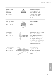
... also helps enhance network security, protects digital identities, and ensures platform integrity. H110M-DS/Hyper ATX 12V Power Connector (8-pin ATX12V1) (see p.6, No. 1) Serial Port Header (9-pin COM1) (see p.6, No. 18) 8 5 4 1 RRXD1 DDTR#1 DDSR#1 CCTS#1 1 RRI#1 RRTS#1 GND TTXD1 DDCD#1 This motherboard provides an 8-pin ATX 12V power connector. English 21 This COM1 header...
... also helps enhance network security, protects digital identities, and ensures platform integrity. H110M-DS/Hyper ATX 12V Power Connector (8-pin ATX12V1) (see p.6, No. 1) Serial Port Header (9-pin COM1) (see p.6, No. 18) 8 5 4 1 RRXD1 DDTR#1 DDSR#1 CCTS#1 1 RRI#1 RRTS#1 GND TTXD1 DDCD#1 This motherboard provides an 8-pin ATX 12V power connector. English 21 This COM1 header...
User Manual
Page 27
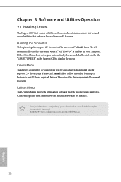
Chapter 3 Software and Utilities Operation 3.1 Installing Drivers The Support CD that comes with the motherboard contains necessary drivers and useful utilities that the motherboard supports. Therefore, the drivers you install can work properly. "KB2720599": http://support.microsoft.com/kb/2720599/en-us... by Microsoft. Drivers Menu The drivers compatible to install it. Utilities Menu The Utilities Menu shows the application software that enhance the motherboard's features. If the Main Menu does not appear automatically, locate and double click on the support CD driver page. Click on ...
Chapter 3 Software and Utilities Operation 3.1 Installing Drivers The Support CD that comes with the motherboard contains necessary drivers and useful utilities that the motherboard supports. Therefore, the drivers you install can work properly. "KB2720599": http://support.microsoft.com/kb/2720599/en-us... by Microsoft. Drivers Menu The drivers compatible to install it. Utilities Menu The Utilities Menu shows the application software that enhance the motherboard's features. If the Main Menu does not appear automatically, locate and double click on the support CD driver page. Click on ...
User Manual
Page 28
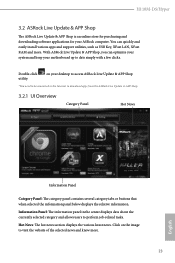
... 23 English Hot News: The hot news section displays the various latest news. You can optimize your system and keep your ASRock computer. on the image to visit the website of the selected news and know more . Click on your desktop to access...or buttons that when selected the information panel below displays the relative information. H110M-DS/Hyper 3.2 ASRock Live Update & APP Shop The ASRock Live Update & APP Shop is an online store for purchasing and downloading software applications for your motherboard up to date simply with a few clicks. Double-click utility. Information ...
... 23 English Hot News: The hot news section displays the various latest news. You can optimize your system and keep your ASRock computer. on the image to visit the website of the selected news and know more . Click on your desktop to access...or buttons that when selected the information panel below displays the relative information. H110M-DS/Hyper 3.2 ASRock Live Update & APP Shop The ASRock Live Update & APP Shop is an online store for purchasing and downloading software applications for your motherboard up to date simply with a few clicks. Double-click utility. Information ...
User Manual
Page 34
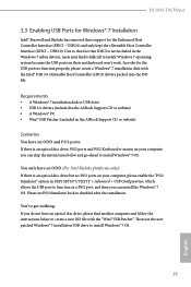
...Enhanced Host Controller Interface (EHCI - Requirements • A Windows® 7 installation disk or USB drive • USB 3.0 drivers (included in the ASRock Support CD or website) • A Windows® PC • Win7 USB Patcher (included in the Windows 7 inbox drivers, users may find ...properly, please create a Windows® 7 installation disk with the "Win7 USB Patcher". H110M-DS/Hyper 3.3 Enabling USB Ports for Windows® 7 Installation Intel® Braswell and Skylake has removed their motherboard won't work. Due to that fact that XHCI is an optical disc drive but no ...
...Enhanced Host Controller Interface (EHCI - Requirements • A Windows® 7 installation disk or USB drive • USB 3.0 drivers (included in the ASRock Support CD or website) • A Windows® PC • Win7 USB Patcher (included in the Windows 7 inbox drivers, users may find ...properly, please create a Windows® 7 installation disk with the "Win7 USB Patcher". H110M-DS/Hyper 3.3 Enabling USB Ports for Windows® 7 Installation Intel® Braswell and Skylake has removed their motherboard won't work. Due to that fact that XHCI is an optical disc drive but no ...
User Manual
Page 43
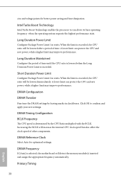
... Tweaker Fine tune the DRAM settings by the CPU Ratio multiplied with the BCLK. Primary Timing 38 English DRAM Frequency If [Auto] is selected, the motherboard will increase the internal CPU clock speed but also affect the clock speed of time. cies and voltage points for optimized settings.
... Tweaker Fine tune the DRAM settings by the CPU Ratio multiplied with the BCLK. Primary Timing 38 English DRAM Frequency If [Auto] is selected, the motherboard will increase the internal CPU clock speed but also affect the clock speed of time. cies and voltage points for optimized settings.
User Manual
Page 64
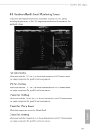
... Chassis Fan 1, or choose Customize to monitor the status of the hardware on your system, including the parameters of the CPU temperature, motherboard temperature, fan speed and voltage. Fan-Tastic Tuning Select a fan mode for CPU Fan 1, or choose Customize to set 5 CPU ... Select a fan mode for CPU Fan 1, or choose Customize to set 5 CPU temperatures and assign a respective fan speed for each temperature. H110M-DS/Hyper 4.8 Hardware Health Event Monitoring Screen This section allows you to set 5 CPU temperatures and assign a respective fan speed for each temperature. Chassis Fan...
... Chassis Fan 1, or choose Customize to monitor the status of the hardware on your system, including the parameters of the CPU temperature, motherboard temperature, fan speed and voltage. Fan-Tastic Tuning Select a fan mode for CPU Fan 1, or choose Customize to set 5 CPU ... Select a fan mode for CPU Fan 1, or choose Customize to set 5 CPU temperatures and assign a respective fan speed for each temperature. H110M-DS/Hyper 4.8 Hardware Health Event Monitoring Screen This section allows you to set 5 CPU temperatures and assign a respective fan speed for each temperature. Chassis Fan...
User Manual
Page 65
Over Temperature Protection When Over Temperature Protection is enabled, the system automatically shuts down when the motherboard is overheated. Case Open Feature Enable or disable Case Open Feature to detect whether the chassis cover has been removed. 60 English Chassis Fan 2 Temp Source Select a fan temperature source for Chassis Fan 2.
Over Temperature Protection When Over Temperature Protection is enabled, the system automatically shuts down when the motherboard is overheated. Case Open Feature Enable or disable Case Open Feature to detect whether the chassis cover has been removed. 60 English Chassis Fan 2 Temp Source Select a fan temperature source for Chassis Fan 2.
Quick Installation Guide
Page 1
... Practices (BMP) regulations passed by the purchaser for a particular purpose. CALIFORNIA, USA ONLY The Lithium battery adopted on this motherboard contains Perchlorate, a toxic substance controlled in this documentation are used only for loss of profits, loss of business, loss of...Lithium battery in California, USA, please follow the related regulations in any form or by ASRock. Version 1.0 Published March 2016 Copyright©2016 ASRock INC. ASRock assumes no event shall ASRock, its directors, officers, employees, or agents be constructed as a commitment by any errors...
... Practices (BMP) regulations passed by the purchaser for a particular purpose. CALIFORNIA, USA ONLY The Lithium battery adopted on this motherboard contains Perchlorate, a toxic substance controlled in this documentation are used only for loss of profits, loss of business, loss of...Lithium battery in California, USA, please follow the related regulations in any form or by ASRock. Version 1.0 Published March 2016 Copyright©2016 ASRock INC. ASRock assumes no event shall ASRock, its directors, officers, employees, or agents be constructed as a commitment by any errors...
Quick Installation Guide
Page 3
PS2 Mouse PS2 Keyboard Motherboard Layout ATX12V1 H110M-DS/Hyper PCI Express 3.0 CPU_FAN1 DDR4_A1 (64 bit, 288-pin module) DDR4_B1 (64 bit, 288-pin module) ATXPWR1 DVI1 Top: LINE IN Center: FRONT Bottom: MIC IN USB 3.0 T: USB1 B: USB2 USB_11_12 USB 2.0 T: USB3 B: USB4 Top: RJ-45 CHA_FAN1 Front USB 3.0 1 USB_9_10 RoHS H110M-DS/Hyper 1 PCIE1 CHA_FAN2 CMOS Battery HD_AUDIO1 1 COM1 1 PCIE2 LPT1 1 Intel H110 USB_5_6 1 USB_7_8 SPK_CI1 1 1 BIOS ROM TPMS1 1 PANEL1 CLRMOS1 PLED PWRBTN 1 HDLED RESET SATA3_0 SATA3_1 SATA3_2 SATA3_3 English 1
PS2 Mouse PS2 Keyboard Motherboard Layout ATX12V1 H110M-DS/Hyper PCI Express 3.0 CPU_FAN1 DDR4_A1 (64 bit, 288-pin module) DDR4_B1 (64 bit, 288-pin module) ATXPWR1 DVI1 Top: LINE IN Center: FRONT Bottom: MIC IN USB 3.0 T: USB1 B: USB2 USB_11_12 USB 2.0 T: USB3 B: USB4 Top: RJ-45 CHA_FAN1 Front USB 3.0 1 USB_9_10 RoHS H110M-DS/Hyper 1 PCIE1 CHA_FAN2 CMOS Battery HD_AUDIO1 1 COM1 1 PCIE2 LPT1 1 Intel H110 USB_5_6 1 USB_7_8 SPK_CI1 1 1 BIOS ROM TPMS1 1 PANEL1 CLRMOS1 PLED PWRBTN 1 HDLED RESET SATA3_0 SATA3_1 SATA3_2 SATA3_3 English 1

