
User Manual
Page 4
... 1 1.2 Specifications 2 1.3 Motherboard Layout 6 1.4 I/O Panel 8 Chapter 2 Installation 10 2.1 Installing the CPU 11 2.2 Installing the CPU Fan and Heatsink 14 2.3 Installing Memory Modules (DIMM) 15 2.4 Expansion Slots (PCI Express Slots) 17 2.5 Onboard Headers and Connectors 18 Chapter 3 Software and Utilities Operation 22 3.1 Installing Drivers 22 3.2 ASRock Live Update & APP Shop 23 3.2.1 UI Overview 23 3.2.2 Apps 24 3.2.3 BIOS & Drivers 27 3.2.4 Setting 28 3.3 Enabling USB Ports for Windows® 7 Installation 29 Chapter 4 UEFI SETUP UTILITY 32...
... 1 1.2 Specifications 2 1.3 Motherboard Layout 6 1.4 I/O Panel 8 Chapter 2 Installation 10 2.1 Installing the CPU 11 2.2 Installing the CPU Fan and Heatsink 14 2.3 Installing Memory Modules (DIMM) 15 2.4 Expansion Slots (PCI Express Slots) 17 2.5 Onboard Headers and Connectors 18 Chapter 3 Software and Utilities Operation 22 3.1 Installing Drivers 22 3.2 ASRock Live Update & APP Shop 23 3.2.1 UI Overview 23 3.2.2 Apps 24 3.2.3 BIOS & Drivers 27 3.2.4 Setting 28 3.3 Enabling USB Ports for Windows® 7 Installation 29 Chapter 4 UEFI SETUP UTILITY 32...
User Manual
Page 6
H110M-DS/Hyper Chapter 1 Introduction Thank you are using. Chapter 3 contains the operation guide of this documentation occur, the updated version will be subject to change without further notice. Because the motherboard specifications and the BIOS software might be available on ASRock's website as well. In case any modifications of the BIOS setup. You may find the latest VGA cards and CPU support list on ASRock's website without notice. It delivers excellent performance...
H110M-DS/Hyper Chapter 1 Introduction Thank you are using. Chapter 3 contains the operation guide of this documentation occur, the updated version will be subject to change without further notice. Because the motherboard specifications and the BIOS software might be available on ASRock's website as well. In case any modifications of the BIOS setup. You may find the latest VGA cards and CPU support list on ASRock's website without notice. It delivers excellent performance...
User Manual
Page 8
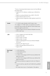
.../2 Mouse Port • 1 x PS/2 Keyboard Port • 1 x DVI-D Port • 2 x USB 2.0 Ports (Supports ESD Protection (ASRock Full Spike Protection))* • 2 x USB 3.0 Ports (Supports ESD Protection (ASRock Full Spike Protection))* * ACPI wake-up function is supported on the rear USB ports only. • 1 x RJ-45 LAN Port with max. H110M-DS/Hyper * The size of maximum shared memory may vary from different operating systems. • Supports DVI-D with LED (ACT/LINK LED and SPEED LED) • HD Audio Jacks: Line in / Front Speaker...
.../2 Mouse Port • 1 x PS/2 Keyboard Port • 1 x DVI-D Port • 2 x USB 2.0 Ports (Supports ESD Protection (ASRock Full Spike Protection))* • 2 x USB 3.0 Ports (Supports ESD Protection (ASRock Full Spike Protection))* * ACPI wake-up function is supported on the rear USB ports only. • 1 x RJ-45 LAN Port with max. H110M-DS/Hyper * The size of maximum shared memory may vary from different operating systems. • Supports DVI-D with LED (ACT/LINK LED and SPEED LED) • HD Audio Jacks: Line in / Front Speaker...
User Manual
Page 9
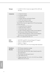
...; AMI UEFI Legal BIOS with USB_9_10. Storage • 4 x SATA3 6.0 Gb/s Connectors, support NCQ, AHCI and Hot Plug Connector • 1 x Print Port Header • 1 x COM Port Header • 1 x TPM Header • 1 x Chassis Intrusion and Speaker Header • 1 x CPU Fan Connector (4-pin) • 2 x Chassis Fan Connectors (4-pin) * The CPU Fan Connector supports the CPU fan of maximum 1A (12W) fan power. • 1 x 24 pin ATX Power Connector • 1 x 8 pin 12V Power Connector • 1 x Front Panel Audio Connector • 3 x USB 2.0 Headers (Support 6 USB 2.0 ports) (Supports ESD...
...; AMI UEFI Legal BIOS with USB_9_10. Storage • 4 x SATA3 6.0 Gb/s Connectors, support NCQ, AHCI and Hot Plug Connector • 1 x Print Port Header • 1 x COM Port Header • 1 x TPM Header • 1 x Chassis Intrusion and Speaker Header • 1 x CPU Fan Connector (4-pin) • 2 x Chassis Fan Connectors (4-pin) * The CPU Fan Connector supports the CPU fan of maximum 1A (12W) fan power. • 1 x 24 pin ATX Power Connector • 1 x 8 pin 12V Power Connector • 1 x Front Panel Audio Connector • 3 x USB 2.0 Headers (Support 6 USB 2.0 ports) (Supports ESD...
User Manual
Page 12
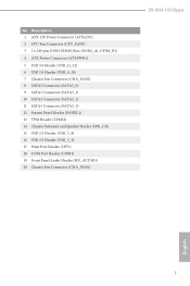
... 2 x 288-pin DDR4 DIMM Slots (DDR4_A1, DDR4_B1) 4 ATX Power Connector (ATXPWR1) 5 USB 3.0 Header (USB_11_12) 6 USB 2.0 Header (USB_9_10) 7 Chassis Fan Connector (CHA_FAN2) 8 SATA3 Connector (SATA3_0) 9 SATA3 Connector (SATA3_1) 10 SATA3 Connector (SATA3_2) 11 SATA3 Connector (SATA3_3) 12 System Panel Header (PANEL1) 13 TPM Header (TPMS1) 14 Chassis Intrusion and Speaker Header (SPK_CI1) 15 USB 2.0 Header (USB_7_8) 16 USB 2.0 Header (USB_5_6) 17 Print Port Header (LPT1) 18 COM Port Header (COM1) 19 Front Panel Audio Header (HD_AUDIO1) 20 Chassis Fan Connector (CHA_FAN1) H110M-DS/Hyper English...
... 2 x 288-pin DDR4 DIMM Slots (DDR4_A1, DDR4_B1) 4 ATX Power Connector (ATXPWR1) 5 USB 3.0 Header (USB_11_12) 6 USB 2.0 Header (USB_9_10) 7 Chassis Fan Connector (CHA_FAN2) 8 SATA3 Connector (SATA3_0) 9 SATA3 Connector (SATA3_1) 10 SATA3 Connector (SATA3_2) 11 SATA3 Connector (SATA3_3) 12 System Panel Header (PANEL1) 13 TPM Header (TPMS1) 14 Chassis Intrusion and Speaker Header (SPK_CI1) 15 USB 2.0 Header (USB_7_8) 16 USB 2.0 Header (USB_5_6) 17 Print Port Header (LPT1) 18 COM Port Header (COM1) 19 Front Panel Audio Header (HD_AUDIO1) 20 Chassis Fan Connector (CHA_FAN1) H110M-DS/Hyper English...
User Manual
Page 22
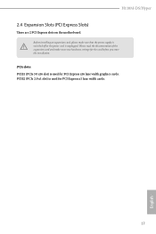
PCIe slots: PCIE1 (PCIe 3.0 x16 slot) is used for PCI Express x1 lane width cards. 17 English PCIE2 (PCIe 2.0 x1 slot) is unplugged. Please read the documentation of the expansion card and make sure that the power supply is switched off or the power cord is used for the card before you start the installation. H110M-DS/Hyper 2.4 Expansion Slots (PCI Express Slots) There are 2 PCI Express slots on the motherboard. Before installing an expansion card, please make necessary hardware settings for PCI Express x16 lane width graphics cards.
PCIe slots: PCIE1 (PCIe 3.0 x16 slot) is used for PCI Express x1 lane width cards. 17 English PCIE2 (PCIe 2.0 x1 slot) is unplugged. Please read the documentation of the expansion card and make sure that the power supply is switched off or the power cord is used for the card before you start the installation. H110M-DS/Hyper 2.4 Expansion Slots (PCI Express Slots) There are 2 PCI Express slots on the motherboard. Before installing an expansion card, please make necessary hardware settings for PCI Express x16 lane width graphics cards.
User Manual
Page 27
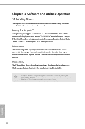
... auto-detected and listed on the file "ASRSETUP.EXE" in your CD-ROM drive. "KB2720599": http://support.microsoft.com/kb/2720599/en-us 22 English Utilities Menu The Utilities Menu shows the application software that enhance the motherboard's features. The CD automatically displays the Main Menu if "AUTORUN" is enabled in the Support CD to install it. Therefore, the drivers you install can work properly. Running The Support CD To begin using the support...
... auto-detected and listed on the file "ASRSETUP.EXE" in your CD-ROM drive. "KB2720599": http://support.microsoft.com/kb/2720599/en-us 22 English Utilities Menu The Utilities Menu shows the application software that enhance the motherboard's features. The CD automatically displays the Main Menu if "AUTORUN" is enabled in the Support CD to install it. Therefore, the drivers you install can work properly. Running The Support CD To begin using the support...
User Manual
Page 34
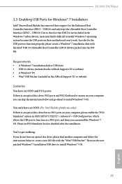
... USB drive • USB 3.0 drivers (included in the ASRock Support CD or website) • A Windows® PC • Win7 USB Patcher (included in the ASRock Support CD or website) Scenarios You have an ODD and PS/2 ports: If there is not included in UEFI SETUP UTILITY > Advanced > USB Configuration, which allows the USB port to function as a PS/2 port, and then you can skip the instructions below to install Windows® 7 OS. H110M-DS/Hyper 3.3 Enabling USB Ports...
... USB drive • USB 3.0 drivers (included in the ASRock Support CD or website) • A Windows® PC • Win7 USB Patcher (included in the ASRock Support CD or website) Scenarios You have an ODD and PS/2 ports: If there is not included in UEFI SETUP UTILITY > Advanced > USB Configuration, which allows the USB port to function as a PS/2 port, and then you can skip the instructions below to install Windows® 7 OS. H110M-DS/Hyper 3.3 Enabling USB Ports...
User Manual
Page 35
Instructions Step 1 Insert the Windows® 7 installation disk or USB drive to your CD-ROM. 30 English If you are using ASRock's Support CD for the USB 3.0 driver, please select your system. Step 4 Select the "USB Driver Folder" by clicking the red circle as shown as the picture below . Step 3 Select the "Win7 Folder" from Step1 by clicking the red circle as shown as the picture below . Step 2 Extract the tool (Win7 USB Patcher) and launch it.
Instructions Step 1 Insert the Windows® 7 installation disk or USB drive to your CD-ROM. 30 English If you are using ASRock's Support CD for the USB 3.0 driver, please select your system. Step 4 Select the "USB Driver Folder" by clicking the red circle as shown as the picture below . Step 3 Select the "Win7 Folder" from Step1 by clicking the red circle as shown as the picture below . Step 2 Extract the tool (Win7 USB Patcher) and launch it.
User Manual
Page 42
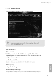
... will set up overclocking features. Intel SpeedStep Technology Intel SpeedStep technology allows processors to switch between multiple frequen- 37 English Boot Performance Mode Select the performance state that the BIOS will increase the internal CPU clock speed but also affect the clock speed of other components. H110M-DS/Hyper Because the UEFI software is determined by the CPU Ratio multiplied with the BCLK. CPU Configuration BCLK Frequency The CPU speed is constantly being updated, the following UEFI setup screens and...
... will set up overclocking features. Intel SpeedStep Technology Intel SpeedStep technology allows processors to switch between multiple frequen- 37 English Boot Performance Mode Select the performance state that the BIOS will increase the internal CPU clock speed but also affect the clock speed of other components. H110M-DS/Hyper Because the UEFI software is determined by the CPU Ratio multiplied with the BCLK. CPU Configuration BCLK Frequency The CPU speed is constantly being updated, the following UEFI setup screens and...
User Manual
Page 54
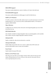
... installed. H110M-DS/Hyper DMI ASPM Support This option enables/disables the control of ASPM on AC/Power Loss Select the power state after a power failure. Onboard HD Audio Enable/disable onboard HD audio. Enable/disable IOAPIC 24-119 Entries to expand to disable the integrated graphics when an external graphics card is selected, the power will start to keep the integrated graphics enabled at all PCH DMI devices. Select enable to boot up . If [Power Off] is installed. Front Panel Enable/disable front panel HD audio. Onboard LAN Enable or disable the onboard network...
... installed. H110M-DS/Hyper DMI ASPM Support This option enables/disables the control of ASPM on AC/Power Loss Select the power state after a power failure. Onboard HD Audio Enable/disable onboard HD audio. Enable/disable IOAPIC 24-119 Entries to expand to disable the integrated graphics when an external graphics card is selected, the power will start to keep the integrated graphics enabled at all PCH DMI devices. Select enable to boot up . If [Power Off] is installed. Front Panel Enable/disable front panel HD audio. Onboard LAN Enable or disable the onboard network...
User Manual
Page 56
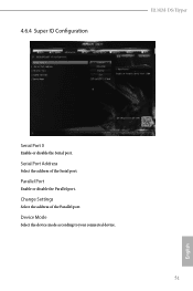
4.6.4 Super IO Configuration H110M-DS/Hyper Serial Port 0 Enable or disable the Serial port. Change Settings Select the address of the Serial port. Device Mode Select the device mode according to your connected device. 51 English Parallel Port Enable or disable the Parallel port. Serial Port Address Select the address of the Parallel port.
4.6.4 Super IO Configuration H110M-DS/Hyper Serial Port 0 Enable or disable the Serial port. Change Settings Select the address of the Serial port. Device Mode Select the device mode according to your connected device. 51 English Parallel Port Enable or disable the Parallel port. Serial Port Address Select the address of the Parallel port.
User Manual
Page 61
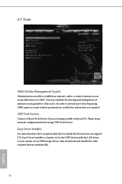
... OMG (Online Management Guard) Administrators are able to establish an internet curfew or restrict internet access at specified times via an USB storage device, then downloads and installs the other users. You may schedule the starting and ending hours of internet access granted to other required drivers automatically. 56 English UEFI Tech Service Contact ASRock Tech Service if you are required. Please setup network configuration before using UEFI Tech Service.
... OMG (Online Management Guard) Administrators are able to establish an internet curfew or restrict internet access at specified times via an USB storage device, then downloads and installs the other users. You may schedule the starting and ending hours of internet access granted to other required drivers automatically. 56 English UEFI Tech Service Contact ASRock Tech Service if you are required. Please setup network configuration before using UEFI Tech Service.
User Manual
Page 62
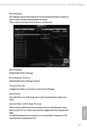
... users to easily customize and manage the boot menu. *Please connect more than one boot devices to use this function. 57 English Please setup network configuration before using Internet Flash. *For BIOS backup and recovery purpose, it is specifically designed for the Boot Manager. Instant Flash Save UEFI files in your USB storage device and run Instant Flash to plug in your UEFI. Internet Flash - Boot Manager Timeout Enable/disable the Boot Manager Timeout. DHCP (Auto IP), Auto ASRock Internet Flash downloads and updates the latest UEFI firmware version...
... users to easily customize and manage the boot menu. *Please connect more than one boot devices to use this function. 57 English Please setup network configuration before using Internet Flash. *For BIOS backup and recovery purpose, it is specifically designed for the Boot Manager. Instant Flash Save UEFI files in your USB storage device and run Instant Flash to plug in your UEFI. Internet Flash - Boot Manager Timeout Enable/disable the Boot Manager Timeout. DHCP (Auto IP), Auto ASRock Internet Flash downloads and updates the latest UEFI firmware version...
User Manual
Page 63
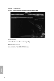
UEFI Download Server Select a server to configure internet connection settings for Internet Flash. Internet Setting Enable or disable sound effects in the setup utility. Network Configuration Use this to download the UEFI firmware. 58 English
UEFI Download Server Select a server to configure internet connection settings for Internet Flash. Internet Setting Enable or disable sound effects in the setup utility. Network Configuration Use this to download the UEFI firmware. 58 English
User Manual
Page 66
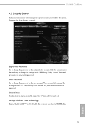
.... User Password Set or change the password for Windows 8.1 Secure Boot. Disable this item to use discrete TPM Module. 61 English Only the administrator has authority to change the settings in the UEFI Setup Utility. Supervisor Password Set or change the password for the system. Users are unable to change the supervisor/user password for the user account. Leave it blank and press enter to remove the password. Leave it blank and press enter to remove the password. H110M-DS/Hyper 4.9 Security Screen...
.... User Password Set or change the password for Windows 8.1 Secure Boot. Disable this item to use discrete TPM Module. 61 English Only the administrator has authority to change the settings in the UEFI Setup Utility. Supervisor Password Set or change the password for the system. Users are unable to change the supervisor/user password for the user account. Leave it blank and press enter to remove the password. Leave it blank and press enter to remove the password. H110M-DS/Hyper 4.9 Security Screen...
Quick Installation Guide
Page 4
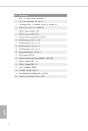
...) 2 CPU Fan Connector (CPU_FAN1) 3 2 x 288-pin DDR4 DIMM Slots (DDR4_A1, DDR4_B1) 4 ATX Power Connector (ATXPWR1) 5 USB 3.0 Header (USB_11_12) 6 USB 2.0 Header (USB_9_10) 7 Chassis Fan Connector (CHA_FAN2) 8 SATA3 Connector (SATA3_0) 9 SATA3 Connector (SATA3_1) 10 SATA3 Connector (SATA3_2) 11 SATA3 Connector (SATA3_3) 12 System Panel Header (PANEL1) 13 TPM Header (TPMS1) 14 Chassis Intrusion and Speaker Header (SPK_CI1) 15 USB 2.0 Header (USB_7_8) 16 USB 2.0 Header (USB_5_6) 17 Print Port Header (LPT1) 18 COM Port Header (COM1) 19 Front Panel Audio Header (HD_AUDIO1) 20 Chassis Fan Connector...
...) 2 CPU Fan Connector (CPU_FAN1) 3 2 x 288-pin DDR4 DIMM Slots (DDR4_A1, DDR4_B1) 4 ATX Power Connector (ATXPWR1) 5 USB 3.0 Header (USB_11_12) 6 USB 2.0 Header (USB_9_10) 7 Chassis Fan Connector (CHA_FAN2) 8 SATA3 Connector (SATA3_0) 9 SATA3 Connector (SATA3_1) 10 SATA3 Connector (SATA3_2) 11 SATA3 Connector (SATA3_3) 12 System Panel Header (PANEL1) 13 TPM Header (TPMS1) 14 Chassis Intrusion and Speaker Header (SPK_CI1) 15 USB 2.0 Header (USB_7_8) 16 USB 2.0 Header (USB_5_6) 17 Print Port Header (LPT1) 18 COM Port Header (COM1) 19 Front Panel Audio Header (HD_AUDIO1) 20 Chassis Fan Connector...
Quick Installation Guide
Page 10
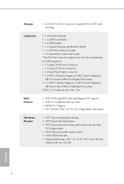
...; AMI UEFI Legal BIOS with USB_9_10. Storage • 4 x SATA3 6.0 Gb/s Connectors, support NCQ, AHCI and Hot Plug Connector • 1 x Print Port Header • 1 x COM Port Header • 1 x TPM Header • 1 x Chassis Intrusion and Speaker Header • 1 x CPU Fan Connector (4-pin) • 2 x Chassis Fan Connectors (4-pin) * The CPU Fan Connector supports the CPU fan of maximum 1A (12W) fan power. • 1 x 24 pin ATX Power Connector • 1 x 8 pin 12V Power Connector • 1 x Front Panel Audio Connector • 3 x USB 2.0 Headers (Support 6 USB 2.0 ports) (Supports ESD...
...; AMI UEFI Legal BIOS with USB_9_10. Storage • 4 x SATA3 6.0 Gb/s Connectors, support NCQ, AHCI and Hot Plug Connector • 1 x Print Port Header • 1 x COM Port Header • 1 x TPM Header • 1 x Chassis Intrusion and Speaker Header • 1 x CPU Fan Connector (4-pin) • 2 x Chassis Fan Connectors (4-pin) * The CPU Fan Connector supports the CPU fan of maximum 1A (12W) fan power. • 1 x 24 pin ATX Power Connector • 1 x 8 pin 12V Power Connector • 1 x Front Panel Audio Connector • 3 x USB 2.0 Headers (Support 6 USB 2.0 ports) (Supports ESD...
Quick Installation Guide
Page 126
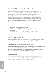
... UEFI SETUP UTILITY > Advanced > USB Configuration, which allows the USB port to function properly, please create a Windows® 7 installation disk with the "Win7 USB Patcher". Enabling USB Ports for Windows® 7 Installation Intel® Braswell and Skylake has removed their motherboard won't work. USB2.0) and only kept the eXtensible Host Controller Interface (XHCI - You only have an optical disc drive, please find it difficult to install Windows 7 operating system because the USB ports on their support...
... UEFI SETUP UTILITY > Advanced > USB Configuration, which allows the USB port to function properly, please create a Windows® 7 installation disk with the "Win7 USB Patcher". Enabling USB Ports for Windows® 7 Installation Intel® Braswell and Skylake has removed their motherboard won't work. USB2.0) and only kept the eXtensible Host Controller Interface (XHCI - You only have an optical disc drive, please find it difficult to install Windows 7 operating system because the USB ports on their support...
Quick Installation Guide
Page 127
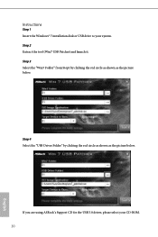
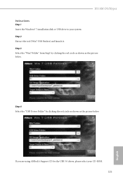
If you are using ASRock's Support CD for the USB 3.0 driver, please select your system. Step 2 Extract the tool (Win7 USB Patcher) and launch it. Step 4 Select the "USB Driver Folder" by clicking the red circle as shown as the picture below . Step 3 Select the "Win7 Folder" from Step1 by clicking the red circle as shown as the picture below . H110M-DS/Hyper Instructions Step 1 Insert the Windows® 7 installation disk or USB drive to your CD-ROM. 125 English
If you are using ASRock's Support CD for the USB 3.0 driver, please select your system. Step 2 Extract the tool (Win7 USB Patcher) and launch it. Step 4 Select the "USB Driver Folder" by clicking the red circle as shown as the picture below . Step 3 Select the "Win7 Folder" from Step1 by clicking the red circle as shown as the picture below . H110M-DS/Hyper Instructions Step 1 Insert the Windows® 7 installation disk or USB drive to your CD-ROM. 125 English


